EP1507106B1 - Garniture d'étanchéité rotative - Google Patents
Garniture d'étanchéité rotative Download PDFInfo
- Publication number
- EP1507106B1 EP1507106B1 EP03405596A EP03405596A EP1507106B1 EP 1507106 B1 EP1507106 B1 EP 1507106B1 EP 03405596 A EP03405596 A EP 03405596A EP 03405596 A EP03405596 A EP 03405596A EP 1507106 B1 EP1507106 B1 EP 1507106B1
- Authority
- EP
- European Patent Office
- Prior art keywords
- piston ring
- contact surface
- region
- component
- sealing
- Prior art date
- Legal status (The legal status is an assumption and is not a legal conclusion. Google has not performed a legal analysis and makes no representation as to the accuracy of the status listed.)
- Expired - Lifetime
Links
- 239000000463 material Substances 0.000 claims description 24
- 238000007789 sealing Methods 0.000 claims description 22
- 238000000034 method Methods 0.000 claims description 15
- 238000006073 displacement reaction Methods 0.000 claims description 4
- 230000003628 erosive effect Effects 0.000 claims description 3
- 239000003779 heat-resistant material Substances 0.000 description 4
- 230000000694 effects Effects 0.000 description 3
- 230000036316 preload Effects 0.000 description 3
- 239000007779 soft material Substances 0.000 description 3
- 238000003860 storage Methods 0.000 description 3
- 239000011248 coating agent Substances 0.000 description 2
- 238000000576 coating method Methods 0.000 description 2
- 238000003780 insertion Methods 0.000 description 2
- 230000037431 insertion Effects 0.000 description 2
- 238000004519 manufacturing process Methods 0.000 description 2
- 238000005299 abrasion Methods 0.000 description 1
- 229910045601 alloy Inorganic materials 0.000 description 1
- 239000000956 alloy Substances 0.000 description 1
- 230000005540 biological transmission Effects 0.000 description 1
- 150000001875 compounds Chemical class 0.000 description 1
- 230000008094 contradictory effect Effects 0.000 description 1
- 238000001816 cooling Methods 0.000 description 1
- 230000001419 dependent effect Effects 0.000 description 1
- 229910002804 graphite Inorganic materials 0.000 description 1
- 239000010439 graphite Substances 0.000 description 1
- 230000020169 heat generation Effects 0.000 description 1
- 238000010438 heat treatment Methods 0.000 description 1
- 229910001026 inconel Inorganic materials 0.000 description 1
- 238000012423 maintenance Methods 0.000 description 1
- 230000007257 malfunction Effects 0.000 description 1
- 238000005457 optimization Methods 0.000 description 1
- 238000004321 preservation Methods 0.000 description 1
- 238000003303 reheating Methods 0.000 description 1
- 238000007790 scraping Methods 0.000 description 1
- 230000007704 transition Effects 0.000 description 1
Images


Classifications
-
- F—MECHANICAL ENGINEERING; LIGHTING; HEATING; WEAPONS; BLASTING
- F02—COMBUSTION ENGINES; HOT-GAS OR COMBUSTION-PRODUCT ENGINE PLANTS
- F02B—INTERNAL-COMBUSTION PISTON ENGINES; COMBUSTION ENGINES IN GENERAL
- F02B39/00—Component parts, details, or accessories relating to, driven charging or scavenging pumps, not provided for in groups F02B33/00 - F02B37/00
- F02B39/16—Other safety measures for, or other control of, pumps
-
- F—MECHANICAL ENGINEERING; LIGHTING; HEATING; WEAPONS; BLASTING
- F01—MACHINES OR ENGINES IN GENERAL; ENGINE PLANTS IN GENERAL; STEAM ENGINES
- F01D—NON-POSITIVE DISPLACEMENT MACHINES OR ENGINES, e.g. STEAM TURBINES
- F01D11/00—Preventing or minimising internal leakage of working-fluid, e.g. between stages
- F01D11/003—Preventing or minimising internal leakage of working-fluid, e.g. between stages by packing rings; Mechanical seals
-
- F—MECHANICAL ENGINEERING; LIGHTING; HEATING; WEAPONS; BLASTING
- F02—COMBUSTION ENGINES; HOT-GAS OR COMBUSTION-PRODUCT ENGINE PLANTS
- F02B—INTERNAL-COMBUSTION PISTON ENGINES; COMBUSTION ENGINES IN GENERAL
- F02B39/00—Component parts, details, or accessories relating to, driven charging or scavenging pumps, not provided for in groups F02B33/00 - F02B37/00
-
- F—MECHANICAL ENGINEERING; LIGHTING; HEATING; WEAPONS; BLASTING
- F16—ENGINEERING ELEMENTS AND UNITS; GENERAL MEASURES FOR PRODUCING AND MAINTAINING EFFECTIVE FUNCTIONING OF MACHINES OR INSTALLATIONS; THERMAL INSULATION IN GENERAL
- F16J—PISTONS; CYLINDERS; SEALINGS
- F16J15/00—Sealings
- F16J15/16—Sealings between relatively-moving surfaces
- F16J15/34—Sealings between relatively-moving surfaces with slip-ring pressed against a more or less radial face on one member
- F16J15/3436—Pressing means
- F16J15/3448—Pressing means the pressing force resulting from fluid pressure
-
- F—MECHANICAL ENGINEERING; LIGHTING; HEATING; WEAPONS; BLASTING
- F16—ENGINEERING ELEMENTS AND UNITS; GENERAL MEASURES FOR PRODUCING AND MAINTAINING EFFECTIVE FUNCTIONING OF MACHINES OR INSTALLATIONS; THERMAL INSULATION IN GENERAL
- F16J—PISTONS; CYLINDERS; SEALINGS
- F16J15/00—Sealings
- F16J15/16—Sealings between relatively-moving surfaces
- F16J15/34—Sealings between relatively-moving surfaces with slip-ring pressed against a more or less radial face on one member
- F16J15/3464—Mounting of the seal
- F16J15/3472—Means for centering or aligning the contacting faces
-
- F—MECHANICAL ENGINEERING; LIGHTING; HEATING; WEAPONS; BLASTING
- F16—ENGINEERING ELEMENTS AND UNITS; GENERAL MEASURES FOR PRODUCING AND MAINTAINING EFFECTIVE FUNCTIONING OF MACHINES OR INSTALLATIONS; THERMAL INSULATION IN GENERAL
- F16J—PISTONS; CYLINDERS; SEALINGS
- F16J15/00—Sealings
- F16J15/44—Free-space packings
- F16J15/441—Free-space packings with floating ring
Definitions
- the invention relates to the field of exhaust gas turbochargers.
- the piston rings are arranged between a fixed and at least one rotating part and serve as a gas and / or oil seal.
- the piston ring is acted upon during assembly of the turbocharger with radially outward bias and connected to the fixed part non-positively and sealingly.
- the piston ring is pressed by the high applied air or exhaust gas pressure in the direction of the rotating part. This reduces the sealing gap between the piston ring and the rotating part, which leads to the desired sealing effect.
- a newly installed piston ring is ground by rubbing against the rotating part in the axial direction.
- the negative effects of production-related dimensional deviations (tolerances) on the sealing gap during operation are eliminated by grinding.
- the friction between the piston ring and the rotating part leads to a strong heating of the piston ring.
- the piston ring can also be exposed to very high temperatures due to operational reasons. Although the temperatures in stationary operation are relatively constant at a tolerable level. However, it comes when switching off the Turbocharger to a strong reheating, the piston ring temperature can reach the critical for the loss of preload range. Particularly in the case of emergency stops, when cooling measures have to be switched off, very high temperature peaks often result.
- US 3,099,453 discloses a rotary seal for sealing a rotating member against a stationary housing by means of a piston ring and a second ring attached thereto, the second ring attached to the piston ring being ground by frictional contact with one of the two components.
- the attached to the piston ring ring is made of a soft material that supports the Abschleiflui. The seal is ensured by a spring which press the piston ring and the attached second ring in the axial direction against the rotating component.
- EP 1 130 220 A2 discloses a rotary seal for sealing a rotating member against a stationary housing by means of a piston ring which is ground by rubbing on the rotating member in the axial direction.
- the housing is a stop provided, which limits the displaceability of the piston ring in the axial direction.
- the invention is therefore an object of the invention to provide a rotary seal of the type mentioned above and a corresponding piston ring, which ensure the shaft seal completely even at high thermal load.
- the rotary seal according to the invention comprises a piston ring with at least two regions made of different materials, wherein the first region, which comprises a contact surface cooperating with a rotating component, of a soft, easily eroding material for optimally supporting a desired grinding process between the piston ring and the first component and a second region is made of a heat-resistant material for permanent maintenance of the radial prestressing.
- piston ring has the advantage that it with the range of high temperature resistant material, the preservation of required radial prestressing permanently enabled and at the same time optimally supports the desired grinding process between the piston ring and the rotating part with the range of a soft stripping material. Thus, the above-mentioned compromise in the choice of materials is unnecessary.
- a stop is advantageously provided which limits the displaceability of the piston ring in the axial direction. This makes it possible to control the grinding depth of the piston ring during the grinding process.
- the stripping region advantageously has a thickness which corresponds at least to the maximum displaceability of the piston ring up to the stop.
- the piston ring according to the invention is advantageously designed such that the first, soft region is designed in the form of a ring, which is encompassed axially and radially at least on one side by the second, highly heat-resistant region. This prevents the soft area from being pushed radially away from the harder, heat-resistant area during operation.
- Fig. 1 shows schematically a partial view of a turbocharger.
- On the left side of the compressor wheel 1 is indicated, which is fixed on the rotatably mounted shaft 3.
- the shaft in turn is connected to the turbine wheel 2 on the right side.
- the turbine wheel comprises vanes, not shown, via which the turbine wheel is driven by an exhaust gas flow.
- the compressor wheel also includes blades, not shown.
- axial and radial bearings are arranged in the area between the two wheels.
- an arbitrary number of parts can be clamped between an axial stop on the compressor wheel and an axial stop on the shaft, which rotate in the operating state with the shaft and take over sealing and / or bearing functions.
- non-rotating housing parts 4 are arranged, which shield against the storage area on the one hand, the heat generated and on the other hand, the pressure prevailing in the flow channels pressure.
- corresponding rotary seals are arranged between the housing parts 4 and rotating with the shaft parts.
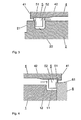
- a turbine-side seal arrangement is shown schematically in Figures 2 and 3. Below each part of the turbine wheel 2 is shown with a circumferential groove 22 for the piston ring 5. Radially outside the turbine wheel, the housing part 4 is arranged. The compressor-side wall of the groove 22 serves as a contact surface 21, which cooperates for sealing with a corresponding contact surface of the sealing ring 5.
- the piston ring 5 is inserted in the groove 22 during assembly. Subsequently, the turbine wheel 2 is inserted from the right in the axial direction in the housing part 4. In this case, the piston ring is subjected to radial bias, since the housing part along the insertion path at one or more points 42 or continuously narrows.
- the piston ring as shown in Fig. 5, advantageously provided with a slot 53 and formed as a snap ring, which allows a corresponding radial bias.
- the piston ring is pushed in the axial direction along the inside of the housing part 4. The piston ring is not clamped in the groove 22, it has axially a game of up to several tenths of a millimeter.
- the piston ring 5 is arranged in the transition region between the compressor wheel 1 connected to the rotating shaft and the non-rotating housing part 4. Between the compressor wheel and an axial stop of the shaft, a clamped, co-rotating part 6, for example a bearing part or a sealing disk, is shown.
- the piston ring 5 is inserted during assembly from the left in the axial direction in the housing part 4. In this case, it is subjected to a radial bias, since the housing part along the insertion path at one or more locations 42 or continuously narrows.
- the piston ring is advantageously formed again as a snap ring.
- the compressor is pushed into the housing part 4 and fixed to the shaft.
- the piston ring is pushed in the axial direction through the axial stop 12 along the inside of the housing part 4 until it is finally arranged at the end of the assembly between the axial stop of the compressor wheel and the sealing washer 6.
- the piston ring is not clamped, it has axially a game of up to several tenths of a millimeter.
- the sealing disc 6 comprises a contact surface 61, which cooperates for sealing with a corresponding contact surface of the sealing ring 5.
- an axial stop 41 is provided on the housing part 4.
- the axial stop limits the axial displaceability of the piston ring. In the operating state of the turbocharger thus takes place in the region of sealingly interacting contact surfaces substantially no power transmission in the axial direction. The directed in the direction of arrow force on the piston ring is counteracted by the axial stop 41.
- the axial extent a of the stripping layer is chosen to be greater than the maximum displacement b of the piston ring limited by the axial stop 41.
- the piston ring 5 shown in detail in FIGS. 5 and 6 comprises two regions 51 and 52 made of different materials.
- FIG. 6 a) shows the piston ring before the first startup of the turbocharger and the associated grinding process, while the piston ring after grinding in Fig. 6 b) is shown. It can clearly be seen that a part 54 of the first area is ground down.
- the stripping region 51 in which the contact surface cooperating with the contact surface 21 of the groove or 61 of the sealing disk, is made of a soft, easily eroding material, for example a nickel-graphite alloy.
- the material of the second region 52 which forms the body of the piston ring, is a harder, but highly heat-resistant material, such as INCONEL.
- the high-temperature-resistant material has the special property that it does not lose its elasticity even at high temperatures. Depending on the material, the spring force responsible for the preload can be maintained at temperatures of up to 600 ° C.
- the stripping layer With an axial width of the piston ring of for example 2.5 to 3.0 mm, it is sufficient to form the stripping layer with a thickness of 0.5 to 0.7 mm. In the case of the grinding process described at the outset, it is thus possible, with only slight heat development, to remove sufficient soft material in order to achieve the desired optimization of the gap seal.
- the body 52 of the piston ring is advantageously first made, for example rotated, first. Subsequently, the stripping layer 51 is applied as a coating, for example flame-sprayed. Previously, a recess provided for the scraping region can be removed from the body of the piston ring.
- the stripping region 51 is bounded radially outwardly by the harder, heat-resistant material. As a result, it is possible to prevent the soft stripping layer from being deformed during operation and being pressed radially outward. In addition, it can better prevent deposits of the material outside the intended area when applying the coating.
- the piston ring according to the invention can also be provided with a plurality of stripping regions, for example when a plurality of rotating parts are to be sealed, or a rotating part has a plurality of mutually separate contact surfaces cooperating with the piston ring.
- the piston ring according to the invention can also be used only on one side, for example only on the turbine side, while the other side is sealed with a conventional piston ring.
Landscapes
- Engineering & Computer Science (AREA)
- General Engineering & Computer Science (AREA)
- Mechanical Engineering (AREA)
- Chemical & Material Sciences (AREA)
- Combustion & Propulsion (AREA)
- Physics & Mathematics (AREA)
- Fluid Mechanics (AREA)
- Supercharger (AREA)
- Sealing Devices (AREA)
- Turbine Rotor Nozzle Sealing (AREA)
Claims (9)
- Segment de piston destiné à réaliser l'étanchéité d'au moins deux composants tournant l'un par rapport à l'autre, le segment de piston présentant une première surface de contact qui est prévue pour coopérer par scellage avec une surface de contact d'un premier des composants, ainsi qu'une deuxième surface de contact qui est prévue pour coopérer par scellage avec une surface de contact d'un deuxième des composants, le segment de piston pouvant être sollicité par une tension radiale pour coopérer par scellage avec l'un des composants et le segment de piston comprenant au moins deux régions (51, 52) en matériaux différents, la première surface de contact étant disposée dans une première (51) des deux régions, caractérisé en ce que la première région (51) est fabriquée en un matériau tendre facilement enlevable pour promouvoir de manière optimale un processus de meulage souhaité entre le segment de piston et le premier composant, et la deuxième région (52) est fabriquée en un matériau résistant à la chaleur pour accepter de manière durable la précontrainte radiale.
- Segment de piston selon la revendication 1, caractérisé en ce que le segment de piston comprend plusieurs premières régions en matériau tendre facilement enlevable.
- Segment de piston selon la revendication 1 ou 2, caractérisé en ce que l'au moins une première région (51) est réalisée avec une forme annulaire, et en ce que la deuxième région (52) entoure la première région axialement et radialement à chaque fois au moins d'un côté.
- Segment de piston selon l'une quelconque des revendications 1 à 3, caractérisé en ce que l'au moins une première région (51) et la deuxième région (52) sont connectées fixement l'une à l'autre.
- Joint d'étanchéité rotatif, comprenant un segment de piston (5) sollicité avec une précontrainte radiale, selon l'une quelconque des revendications 1 à 4, ainsi qu'au moins deux composants (2, 4, 6) à rendre étanche au moyen du segment de piston, les composants présentant, dans la région du segment de piston, des surfaces de contact (21, 61) qui sont en contact hermétique avec le segment de piston et au moins un premier composant (2, 6) et le segment de piston pouvant tourner l'un par rapport à l'autre, la surface de contact (21, 61) du premier composant coopérant hermétiquement avec la première surface de contact du segment de piston.
- Joint d'étanchéité rotatif selon la revendication 5, caractérisé en ce que la surface de contact du deuxième composant (4) coopère hermétiquement avec une deuxième surface de contact correspondante du segment de piston, le segment de piston étant pressé avec une précontrainte contre la surface de contact du deuxième composant, et en ce que le segment de piston peut être déplacé le long de la surface de contact du deuxième composant avec enlèvement au moins partiel de la première région du segment de piston par frottement de la première surface de contact du segment de piston sur la surface de contact (21, 61) du premier composant dans la direction de la surface de contact du premier composant.
- Joint d'étanchéité rotatif selon la revendication 6, caractérisé en ce que la mobilité du segment de piston dans la direction de la surface de contact du premier composant est limitée par une butée (41) et en ce que la première région du segment de piston (51) présente une extension (a) dans la direction de glissement, qui correspond au moins au glissement maximal (b) limité par la butée du segment de piston dans la direction de la surface de contact du premier composant.
- Joint d'étanchéité rotatif selon l'une quelconque des revendications 5 à 7, caractérisé en ce que plusieurs composants sont disposés de manière à pouvoir tourner par rapport au segment de piston, et en ce que le segment de piston comprend de manière correspondante plusieurs régions en matériau tendre facilement enlevable.
- Turbosoufflante comprenant dans un carter, une roue de turbine (2) ainsi qu'une roue de compresseur (1) connectée par le biais d'un arbre (3) monté à rotation à la roue de turbine, caractérisée en ce que l'arbre (3) est rendu étanche par rapport aux parties fixes du carter dans la région de la roue de compresseur et/ou de la roue de turbine au moyen d'un joint d'étanchéité selon l'une quelconque des revendications 5 à 8.
Priority Applications (5)
| Application Number | Priority Date | Filing Date | Title |
|---|---|---|---|
| DE50307710T DE50307710D1 (de) | 2003-08-15 | 2003-08-15 | Rotationsdichtung |
| EP03405596A EP1507106B1 (fr) | 2003-08-15 | 2003-08-15 | Garniture d'étanchéité rotative |
| KR1020040055773A KR101100052B1 (ko) | 2003-08-15 | 2004-07-16 | 회전 시일 |
| JP2004229614A JP4688448B2 (ja) | 2003-08-15 | 2004-08-05 | 回転シール |
| CNB2004100577570A CN100408892C (zh) | 2003-08-15 | 2004-08-16 | 旋转密封装置及包括该装置的涡轮增压器 |
Applications Claiming Priority (1)
| Application Number | Priority Date | Filing Date | Title |
|---|---|---|---|
| EP03405596A EP1507106B1 (fr) | 2003-08-15 | 2003-08-15 | Garniture d'étanchéité rotative |
Publications (2)
| Publication Number | Publication Date |
|---|---|
| EP1507106A1 EP1507106A1 (fr) | 2005-02-16 |
| EP1507106B1 true EP1507106B1 (fr) | 2007-07-18 |
Family
ID=33560914
Family Applications (1)
| Application Number | Title | Priority Date | Filing Date |
|---|---|---|---|
| EP03405596A Expired - Lifetime EP1507106B1 (fr) | 2003-08-15 | 2003-08-15 | Garniture d'étanchéité rotative |
Country Status (5)
| Country | Link |
|---|---|
| EP (1) | EP1507106B1 (fr) |
| JP (1) | JP4688448B2 (fr) |
| KR (1) | KR101100052B1 (fr) |
| CN (1) | CN100408892C (fr) |
| DE (1) | DE50307710D1 (fr) |
Cited By (2)
| Publication number | Priority date | Publication date | Assignee | Title |
|---|---|---|---|---|
| DE202009007436U1 (de) | 2008-09-18 | 2009-09-10 | Abb Turbo Systems Ag | Vorrichtung zum Abdichten eines Lagergehäuses eines Abgasturboladers |
| US8517679B2 (en) | 2009-02-12 | 2013-08-27 | Abb Turbo Systems Ag | Compressor-side shaft seal of an exhaust-gas turbocharger |
Families Citing this family (12)
| Publication number | Priority date | Publication date | Assignee | Title |
|---|---|---|---|---|
| US7066719B2 (en) * | 2004-07-03 | 2006-06-27 | Honeywell International, Inc. | Bore and shaft assembly |
| EP1947373A1 (fr) * | 2007-01-19 | 2008-07-23 | ABB Turbo Systems AG | Dispositif d'étanchéité |
| EP2098688A1 (fr) * | 2008-03-07 | 2009-09-09 | Siemens Aktiengesellschaft | Turbine à gaz |
| JP5039730B2 (ja) * | 2009-02-26 | 2012-10-03 | 三菱重工業株式会社 | 可変容量型排気ターボ過給機 |
| JP5625645B2 (ja) * | 2010-09-07 | 2014-11-19 | 株式会社Ihi | シール構造及び過給機 |
| WO2014143325A1 (fr) * | 2013-03-15 | 2014-09-18 | Copeland Andrew D | Ensemble de joint pour moteur à turbine à gaz et procédé de formage de composant de moteur à turbine |
| US9488227B2 (en) * | 2014-09-17 | 2016-11-08 | Schaeffler Technologies AG & Co. KG | Variable torque bearing |
| WO2016203970A1 (fr) | 2015-06-16 | 2016-12-22 | 株式会社Ihi | Structure d'étanchéité et superchargeur |
| JP6543159B2 (ja) * | 2015-10-13 | 2019-07-10 | 株式会社Ihi回転機械エンジニアリング | 過給機、タービン軸部品、及びシールブッシュ |
| DE102016113198A1 (de) * | 2016-07-18 | 2018-01-18 | Abb Turbo Systems Ag | Kolbenring, Turbolader mit Kolbenring und Verfahren zum Herstellen eines Kolbenrings |
| CN112324524A (zh) * | 2020-11-03 | 2021-02-05 | 中国北方发动机研究所(天津) | 一种增压器复合密封环 |
| KR102949531B1 (ko) * | 2024-05-21 | 2026-04-07 | 효성중공업 주식회사 | 가스절연 개폐장치용 스페이서 |
Family Cites Families (8)
| Publication number | Priority date | Publication date | Assignee | Title |
|---|---|---|---|---|
| US3099453A (en) * | 1959-10-14 | 1963-07-30 | Dresser Operations Inc | Shaft seal with positive automatic shut-down feature |
| GB1430308A (en) * | 1973-04-06 | 1976-03-31 | Woollenweber W E | Rotatable assembly |
| JPS5516526Y2 (fr) * | 1975-03-05 | 1980-04-17 | ||
| JPH041314Y2 (fr) * | 1985-12-26 | 1992-01-17 | ||
| US5270324A (en) * | 1992-04-10 | 1993-12-14 | Merck Frosst Canada, Inc. | Fluorinated hydroxyalkylquinoline acids as leukotriene antagonists |
| US5890881A (en) * | 1996-11-27 | 1999-04-06 | Alliedsignal Inc. | Pressure balanced turbocharger rotating seal |
| GB2359863B (en) * | 2000-03-04 | 2003-03-26 | Alstom | Turbocharger |
| JP2002021752A (ja) * | 2000-07-05 | 2002-01-23 | Fujitsu General Ltd | スクロール圧縮機 |
-
2003
- 2003-08-15 DE DE50307710T patent/DE50307710D1/de not_active Expired - Lifetime
- 2003-08-15 EP EP03405596A patent/EP1507106B1/fr not_active Expired - Lifetime
-
2004
- 2004-07-16 KR KR1020040055773A patent/KR101100052B1/ko not_active Expired - Lifetime
- 2004-08-05 JP JP2004229614A patent/JP4688448B2/ja not_active Expired - Lifetime
- 2004-08-16 CN CNB2004100577570A patent/CN100408892C/zh not_active Expired - Lifetime
Cited By (3)
| Publication number | Priority date | Publication date | Assignee | Title |
|---|---|---|---|---|
| DE202009007436U1 (de) | 2008-09-18 | 2009-09-10 | Abb Turbo Systems Ag | Vorrichtung zum Abdichten eines Lagergehäuses eines Abgasturboladers |
| EP2166259A1 (fr) | 2008-09-18 | 2010-03-24 | ABB Turbo Systems AG | Dispositif d'étanchéification d'un logement de palier d'un turbocompresseur à gaz d'échappement |
| US8517679B2 (en) | 2009-02-12 | 2013-08-27 | Abb Turbo Systems Ag | Compressor-side shaft seal of an exhaust-gas turbocharger |
Also Published As
| Publication number | Publication date |
|---|---|
| CN1580615A (zh) | 2005-02-16 |
| JP2005061621A (ja) | 2005-03-10 |
| EP1507106A1 (fr) | 2005-02-16 |
| JP4688448B2 (ja) | 2011-05-25 |
| DE50307710D1 (de) | 2007-08-30 |
| KR101100052B1 (ko) | 2011-12-29 |
| CN100408892C (zh) | 2008-08-06 |
| KR20050016006A (ko) | 2005-02-21 |
Similar Documents
| Publication | Publication Date | Title |
|---|---|---|
| EP1507106B1 (fr) | Garniture d'étanchéité rotative | |
| DE60004772T2 (de) | Dichtungsanordnung | |
| DE69907859T2 (de) | Abdichtung | |
| DE69921415T2 (de) | Drehring und damit bestückte Gleitringdichtung | |
| EP2344723B1 (fr) | Turbine à gaz avec plaques d'étanchéité sur le disque de turbine | |
| WO2001048887A2 (fr) | Joint brosse | |
| EP1180196A1 (fr) | Turbomachine comportant un systeme d'etancheite pour un rotor | |
| WO2000070191A1 (fr) | Systeme d'etancheite pour un rotor d'une turbomachine | |
| EP3545205B1 (fr) | Système rotatif avec palier radial à gaz | |
| EP2466149A1 (fr) | Turbomachine pour un fluide dotée d'une fente étanche radiale et d'un anneau d'usure stationnaire | |
| DE3925403C2 (de) | Trockengasdichtung | |
| EP3324002B1 (fr) | Système d'étanchéité pour une turbomachine et turbomachine axiale | |
| CH712978B1 (de) | Turbolader. | |
| EP3532740B1 (fr) | Système de rotation comprenant un palier à gaz axial | |
| DE102020101866A1 (de) | Kippsegmentlager und Warmölausleiter für ein solches | |
| EP3613952B1 (fr) | Dispositif d'aube directrice variable, aube directrice, porte-joint et turbomachine | |
| DE102016113198A1 (de) | Kolbenring, Turbolader mit Kolbenring und Verfahren zum Herstellen eines Kolbenrings | |
| EP1653049B1 (fr) | Couronne d'aubes directrices pour turbines à gaz et procédé pour sa modification | |
| WO2009059580A1 (fr) | Composant de turbine à gaz et compresseur comportant un tel composant | |
| EP2561256B1 (fr) | Garniture mecanique d'etancheite dotee d'une contre-bague rotative a serrage defini avec precision | |
| EP3006677B1 (fr) | Turbine a gaz dotee d'au moins deux arbres disposes co-axialement l'un par rapport a l'autre et au moins en partie comme arbres creux | |
| EP1939407B1 (fr) | Turbocompresseur | |
| EP1271023B1 (fr) | Garniture mécanique d'étanchéité | |
| EP3225783B1 (fr) | Garniture de rodage pour un joint externe d'étanchéité à l'air d'une turbomachine | |
| EP4348010B1 (fr) | Bague d'étanchéité d'un rotor et turbomachine comprenant le rotor |
Legal Events
| Date | Code | Title | Description |
|---|---|---|---|
| PUAI | Public reference made under article 153(3) epc to a published international application that has entered the european phase |
Free format text: ORIGINAL CODE: 0009012 |
|
| AK | Designated contracting states |
Kind code of ref document: A1 Designated state(s): AT BE BG CH CY CZ DE DK EE ES FI FR GB GR HU IE IT LI LU MC NL PT RO SE SI SK TR |
|
| AX | Request for extension of the european patent |
Extension state: AL LT LV MK |
|
| 17P | Request for examination filed |
Effective date: 20050625 |
|
| AKX | Designation fees paid |
Designated state(s): CZ DE GB |
|
| 17Q | First examination report despatched |
Effective date: 20051122 |
|
| GRAP | Despatch of communication of intention to grant a patent |
Free format text: ORIGINAL CODE: EPIDOSNIGR1 |
|
| GRAS | Grant fee paid |
Free format text: ORIGINAL CODE: EPIDOSNIGR3 |
|
| GRAA | (expected) grant |
Free format text: ORIGINAL CODE: 0009210 |
|
| AK | Designated contracting states |
Kind code of ref document: B1 Designated state(s): CZ DE GB |
|
| REG | Reference to a national code |
Ref country code: GB Ref legal event code: FG4D Free format text: NOT ENGLISH |
|
| REF | Corresponds to: |
Ref document number: 50307710 Country of ref document: DE Date of ref document: 20070830 Kind code of ref document: P |
|
| GBT | Gb: translation of ep patent filed (gb section 77(6)(a)/1977) |
Effective date: 20070926 |
|
| PLBE | No opposition filed within time limit |
Free format text: ORIGINAL CODE: 0009261 |
|
| STAA | Information on the status of an ep patent application or granted ep patent |
Free format text: STATUS: NO OPPOSITION FILED WITHIN TIME LIMIT |
|
| 26N | No opposition filed |
Effective date: 20080421 |
|
| REG | Reference to a national code |
Ref country code: DE Ref legal event code: R081 Ref document number: 50307710 Country of ref document: DE Owner name: TURBO SYSTEMS SWITZERLAND LTD., CH Free format text: FORMER OWNER: ABB TURBO SYSTEMS AG, BADEN, CH Ref country code: DE Ref legal event code: R082 Ref document number: 50307710 Country of ref document: DE Representative=s name: ZIMMERMANN & PARTNER PATENTANWAELTE MBB, DE Ref country code: DE Ref legal event code: R081 Ref document number: 50307710 Country of ref document: DE Owner name: ABB SCHWEIZ AG, CH Free format text: FORMER OWNER: ABB TURBO SYSTEMS AG, BADEN, CH |
|
| REG | Reference to a national code |
Ref country code: GB Ref legal event code: 732E Free format text: REGISTERED BETWEEN 20210225 AND 20210303 |
|
| REG | Reference to a national code |
Ref country code: GB Ref legal event code: 732E Free format text: REGISTERED BETWEEN 20210304 AND 20210310 |
|
| REG | Reference to a national code |
Ref country code: GB Ref legal event code: 732E Free format text: REGISTERED BETWEEN 20220922 AND 20220928 |
|
| REG | Reference to a national code |
Ref country code: DE Ref legal event code: R081 Ref document number: 50307710 Country of ref document: DE Owner name: TURBO SYSTEMS SWITZERLAND LTD., CH Free format text: FORMER OWNER: ABB SCHWEIZ AG, BADEN, CH |
|
| PGFP | Annual fee paid to national office [announced via postgrant information from national office to epo] |
Ref country code: GB Payment date: 20220823 Year of fee payment: 20 Ref country code: DE Payment date: 20220819 Year of fee payment: 20 Ref country code: CZ Payment date: 20220805 Year of fee payment: 20 |
|
| REG | Reference to a national code |
Ref country code: DE Ref legal event code: R071 Ref document number: 50307710 Country of ref document: DE |
|
| REG | Reference to a national code |
Ref country code: GB Ref legal event code: PE20 Expiry date: 20230814 |
|
| PG25 | Lapsed in a contracting state [announced via postgrant information from national office to epo] |
Ref country code: GB Free format text: LAPSE BECAUSE OF EXPIRATION OF PROTECTION Effective date: 20230814 Ref country code: CZ Free format text: LAPSE BECAUSE OF EXPIRATION OF PROTECTION Effective date: 20230815 |