EP1507228B1 - Lecteur de codes optiques - Google Patents
Lecteur de codes optiques Download PDFInfo
- Publication number
- EP1507228B1 EP1507228B1 EP04013600A EP04013600A EP1507228B1 EP 1507228 B1 EP1507228 B1 EP 1507228B1 EP 04013600 A EP04013600 A EP 04013600A EP 04013600 A EP04013600 A EP 04013600A EP 1507228 B1 EP1507228 B1 EP 1507228B1
- Authority
- EP
- European Patent Office
- Prior art keywords
- illumination
- line
- optics
- scanner according
- focal length
- Prior art date
- Legal status (The legal status is an assumption and is not a legal conclusion. Google has not performed a legal analysis and makes no representation as to the accuracy of the status listed.)
- Expired - Lifetime
Links
Images

Classifications
-
- G—PHYSICS
- G06—COMPUTING OR CALCULATING; COUNTING
- G06K—GRAPHICAL DATA READING; PRESENTATION OF DATA; RECORD CARRIERS; HANDLING RECORD CARRIERS
- G06K7/00—Methods or arrangements for sensing record carriers, e.g. for reading patterns
- G06K7/10—Methods or arrangements for sensing record carriers, e.g. for reading patterns by electromagnetic radiation, e.g. optical sensing; by corpuscular radiation
- G06K7/10544—Methods or arrangements for sensing record carriers, e.g. for reading patterns by electromagnetic radiation, e.g. optical sensing; by corpuscular radiation by scanning of the records by radiation in the optical part of the electromagnetic spectrum
- G06K7/10712—Fixed beam scanning
- G06K7/10722—Photodetector array or CCD scanning
- G06K7/10732—Light sources
-
- G—PHYSICS
- G06—COMPUTING OR CALCULATING; COUNTING
- G06K—GRAPHICAL DATA READING; PRESENTATION OF DATA; RECORD CARRIERS; HANDLING RECORD CARRIERS
- G06K7/00—Methods or arrangements for sensing record carriers, e.g. for reading patterns
- G06K7/10—Methods or arrangements for sensing record carriers, e.g. for reading patterns by electromagnetic radiation, e.g. optical sensing; by corpuscular radiation
- G06K7/10544—Methods or arrangements for sensing record carriers, e.g. for reading patterns by electromagnetic radiation, e.g. optical sensing; by corpuscular radiation by scanning of the records by radiation in the optical part of the electromagnetic spectrum
- G06K7/10821—Methods or arrangements for sensing record carriers, e.g. for reading patterns by electromagnetic radiation, e.g. optical sensing; by corpuscular radiation by scanning of the records by radiation in the optical part of the electromagnetic spectrum further details of bar or optical code scanning devices
- G06K7/10831—Arrangement of optical elements, e.g. lenses, mirrors, prisms
Definitions
- the invention relates to a scanner, in particular for detecting one and / or two-dimensional codes with a receiving optics, which designs the image of a reading line on a linear arrangement of a plurality of photoreceptors and a lighting arrangement, with which the entire reading line is illuminated in a line.
- Such prior art scanners also called line scanners, can identify one-dimensional codes located in the reading line without the need for relative movement between the scanner and the code.
- Scanners according to the operating principle described above, often have the disadvantage that due to insufficient light conditions, or illuminance in the read line, the codes can only be incorrect, incomplete or in the extreme case, not identified at all. Even if a low illuminance could be compensated with a longer exposure time, this will reduce the reading speed. Particularly in conveyor technology, a large field of application for these scanners, these are the conveying speed reducing influences, of great disadvantage.
- the codes are illuminated in the prior art with high-energy light sources, for example sodium vapor lamps, laser diodes, or many diffused emitting LEDs, which in turn has a large-volume, expensive scanner results in addition, a high electrical power consumption has caused a strong self-heating.
- an optical scanner which forms the light of several light sources with a cylindrical lens to a reading line to illuminate the reading line.
- a relatively large proportion of the light emitted by the light sources is not concentrated on the read line, ultimately resulting in less efficient illumination of the read line.
- US Pat. No. 5,504,317 it is known from US Pat. No. 5,504,317 to concentrate the light of a plurality of light sources on a read line by means of a cylindrical lens.
- the illumination arrangement is arranged relatively close to the read line. However, so that this illumination optics does not hinder the receive beam path, the illumination optics and the receiving optics are aligned at an angle to each other.
- light is not limited to the visible light. Under “light” are generally electromagnetic radiation, ie UV light, IR light and visible light to understand, which can usually be used for the operation of these scanners.
- the invention has for its object to increase by optical means, the efficiency of the lighting arrangement such that with a few light sources, which are operated with low energy input, a sufficiently high illuminance is generated, which allows the safe detection of the codes in the shortest possible time.
- the invention provides a scanner with a receiving optics, which designs the image of a reading line on a linear arrangement of a plurality of photoreceptors, and a lighting arrangement, with the entire reading line in a line with a plurality of substantially punctiform light sources arranged side by side in a line , Illuminated, according to the invention, the illumination arrangement has an anamorphic illumination optics, for generating a line-shaped illumination line.
- the advantage of this inventive lighting arrangement is the fact that, through the use of the special anamorphic illumination optics, the radiation emitted by the light sources is largely completely concentrated only on the illumination line.
- the resulting high illuminance in the illumination line not only allows a short exposure and thus code reading time, but also increases the distance of the useful light to the disturbing ambient light.
- the anamorphic illumination optical system is composed of an at least two-stage imaging system.
- this is a short focal length toric convex lens in the immediate vicinity of each individual light source for beam shaping in the meridional plane and at a greater distance, a long focal length, refractive cylindrical lens which detects the light emission of all light sources and influences the beam shaping in the sagittal plane.
- the short focal length toric convex lens has an aspherical contour in its meridional section, because this can improve the aperture ratio and / or reduce the spherical aberration.
- the function of the second long-focal-length refractive cylinder lens which determines the beam guidance in the sagittal plane for all light sources in common, is produced by a hollow cylindrical mirror with a round or parabolic cross-section.
- a parabolic cross-section it is possible, in particular when using a parabolic cross-section, to expand the optically effective opening of the hollow cylinder mirror in relation to its focal length to a value of about 1: 0.5, which corresponds to a numerical aperture of greater than 1. It is thus possible by means of a simple optical component to concentrate a majority of the radiation emitted by all the light sources used on the illumination line.
- optical components of the anamorphic illumination optics are at least partially diffractive optical elements or produced as Fresnel lenses in injection or embossing technology.
- Another advantage of the invention is the fact that, depending on the task on the number and spatial density of the light sources, together with the short focal toric convex lenses, the total length of the illumination can be adjusted within wide limits to the task.
- the overlapping of the partial illumination lines produced by the individual light sources can be determined by the spatial density of the light sources together with an optimized dimensioning of the toric convex lenses, so that they have a substantially homogeneous illumination intensity in the resulting illumination line of all light sources in the longitudinal direction ,
- a further advantage of this two-stage anamorphic illumination optical system is that the width of the illumination line can be determined via the imaging scale of the cylinder optics which are effective in the sagittal plane. This makes it possible to optimally adapt the illumination line to the width of the reading line of the scanner.
- an embodiment that is particularly preferred from the point of view of economical manufacturability is given when the individual short-focal-length toric convex lenses assigned to the light sources are designed in one piece as a lens array for beam shaping in the meridional plane.
- a plurality of LEDs which are arranged on a line at a defined distance, for example on a printed circuit board, can be joined together in one operation with the toric convex lenses of short focal length.
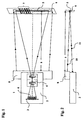
- the scanner 1 in a housing part 2 has a linear arrangement of a plurality of photoreceptors 3.
- This arrangement of the photoreceptor 3 is designed as a spatially resolving detector, in particular as a CCD Unie or CMOS line.
- a reception optics 4, also shown schematically in the housing part 2, designs an image of a reading line 5 located at a reading distance s from the scanner on the surface 6 of the arrangement of the photoreceivers 3.
- a code 7 consisting of differently contrasting contrast marks is applied to the cause individual photocurrents different photocurrents, so that in a downstream evaluation unit, the existing information in the code can be detected.
- a plurality of substantially punctiform light sources are located in a further housing part 8, whose emitted light radiation illuminates a lighting line 9 by means of an anamorphic illumination optics according to the invention.
- the read line 5 and the illumination line 9 overlap at the reading distance s. This is achieved by the optical axis 10 of the illumination optical unit forming an angle with the optical axis 11 of the receiving optical system in the meridional plane. If the scanner is operated in this V-shaped arrangement only in a fixed predetermined reading distance s, then the housing parts 2 and 8 may be firmly connected to each other, or consist of a common housing.
- the housing 2 with the receiving optics and the photoreceptors as well as the housing 8 with the light sources and the anamorphic illumination optics according to the invention adjustable in different angular positions mechanically connected to each other.
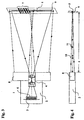
- FIG. 3 shows a preferred embodiment of the scanner in which the anamorphic illumination optics incorporated in the housing part 8 are arranged coplanar with the photoreceivers 3 and the receiving optics 4.
- FIG. 5 a section through the anamorphic illumination optics in the meridional plane, a plurality of substantially punctiform light sources 12, 12 ', to 12 n , in particular LEDs, can be seen, which are arranged offset in line with one another by the distance a.
- the emitted radiation is focused in each case by a short-focal-length toric convex lens 13, 13 ', 13 n in the meridional plane such that the further beam path in this plane has only a slightly divergent character.
- the individual sub-beam 15, 15 n are directed to the illumination line 9.
- the toric of the convex lenses 13, 13 ',, n to 13 n certain divergence of each partial beam of rays 15 to 15 of the line of illumination overlap each other in the plane 9, the partial illumination lines in such a way that, despite the substantially gausförmigen energy distribution of the partial illumination lines a common illumination line 9 with approximately homogeneous energy profile is present.
- FIG. 6 shows, in the sagittal profile cross section of the anamorphic illumination optics, a punctiform light source 12 and the cross section of the toric convex lens 13 in a sectional direction perpendicular to FIG. 3. It can be seen that this is a first approximation to a curved disk of constant center thickness, the optical power is therefore very low. For this reason, the radiation of the light sources will impinge on the surface of the hollow cylinder mirror 14 without any significant change in direction.
- the hollow cylindrical mirror 14 is dimensioned such that the radiation reflected thereon is focused on the illumination line 9 in this sagittal plane.
- the width of the illumination line 9 generated in the focus can thus be influenced via the focal length of the cylinder optics as well as the object and image-side cutting widths.
- the optical function of the hollow cylindrical mirror 14 can also be produced with a continuous plane, concave or biconvex cylindrical lens.
- the beam path from the light source 12, 12 ', to 12 n to the illumination line 9 undergoes no beam reversal, but optionally increases the overall length of the illumination optics.
Landscapes
- Physics & Mathematics (AREA)
- Engineering & Computer Science (AREA)
- Electromagnetism (AREA)
- General Physics & Mathematics (AREA)
- Toxicology (AREA)
- General Health & Medical Sciences (AREA)
- Artificial Intelligence (AREA)
- Computer Vision & Pattern Recognition (AREA)
- Health & Medical Sciences (AREA)
- Theoretical Computer Science (AREA)
- Facsimile Scanning Arrangements (AREA)
- Image Input (AREA)
- Holo Graphy (AREA)
- Silicon Polymers (AREA)
- Light Guides In General And Applications Therefor (AREA)
- Lenses (AREA)
Claims (10)
- Scanneur (1), destiné notamment à la saisie de codes à une et/ou à deux dimensions, comportant une optique de réception qui projette l'image d'une ligne de lecture (5) sur un agencement en forme de lignes de plusieurs photorécepteurs (3), et un dispositif d'éclairage anamorphoseur, avec lequel l'ensemble de la ligne de lecture est éclairé en forme de lignes par plusieurs sources lumineuses (12, 12', 12n) sensiblement ponctuelles disposées côte à côte sur une ligne, caractérisé en ce que le dispositif d'éclairage est constitué d'un système de reproduction à au moins deux étages, comportant à proximité de chaque source lumineuse une lentille convexe torique (13, 13', 13n) à courte distance focale pour la formation du faisceau dans le plan méridien, et ensuite une optique cylindrique (14) de réfraction commune à longue distance focale agissant dans le plan sagittal.
- Scanneur selon la revendication 1, caractérisé en ce que l'optique cylindrique à longue distance focale agissant dans le plan sagittal est constituée d'un miroir cylindrique creux de section transversale ronde ou parabolique.
- Scanneur selon l'une des revendications précédentes, caractérisé en ce que l'optique de l'éclairage anamorphoseur dans le plan méridien et/ou dans le plan sagittal comporte une haute ouverture numérique.
- Scanneur selon l'une des revendications précédentes, caractérisé en ce que les lentilles convexes toriques à courte distance focale de l'optique de l'éclairage anamorphoseur ont un contour non sphérique dans la coupe méridienne.
- Scanneur selon l'une des revendications précédentes, caractérisé en ce que les composants optiques de l'optique de l'éclairage anamorphoseur sont, au moins partiellement, des éléments optiques de diffraction.
- Scanneur selon l'une des revendications précédentes, caractérisé en ce que les éléments optiques de diffraction sont agencés sous la forme de lentilles de Fresnel.
- Scanneur selon l'une des revendications précédentes, caractérisé en ce que la longueur totale de la ligne d'éclairage est réglable par l'intermédiaire du nombre et de la densité dans l'espace des sources lumineuses conjointement avec les lentilles convexes toriques à courte distance focale.
- Scanneur selon l'une des revendications précédentes, caractérisé en ce que la densité dans l'espace des sources lumineuses, et le dimensionnement des lentilles convexes toriques à courte distance focale, sont choisis de telle sorte que l'intensité de l'éclairage soit sensiblement répartie de façon homogène dans la direction longitudinale de la ligne d'éclairage.
- Scanneur selon l'une des revendications précédentes, caractérisé en ce que la largeur de la ligne d'éclairage peut être définie par l'intermédiaire de l'échelle de reproduction de l'optique cylindrique agissant dans le plan sagittal.
- Scanneur selon l'une des revendications précédentes, caractérisé en ce que l'optique de l'éclairage anamorphoseur dans le plan méridien est réalisée d'un seul tenant en tant que réseau de lentilles.
Applications Claiming Priority (2)
| Application Number | Priority Date | Filing Date | Title |
|---|---|---|---|
| DE10337329 | 2003-08-12 | ||
| DE10337329A DE10337329A1 (de) | 2003-08-12 | 2003-08-12 | Codeleser |
Publications (2)
| Publication Number | Publication Date |
|---|---|
| EP1507228A1 EP1507228A1 (fr) | 2005-02-16 |
| EP1507228B1 true EP1507228B1 (fr) | 2006-04-26 |
Family
ID=33560319
Family Applications (1)
| Application Number | Title | Priority Date | Filing Date |
|---|---|---|---|
| EP04013600A Expired - Lifetime EP1507228B1 (fr) | 2003-08-12 | 2004-06-09 | Lecteur de codes optiques |
Country Status (5)
| Country | Link |
|---|---|
| US (1) | US7252237B2 (fr) |
| EP (1) | EP1507228B1 (fr) |
| AT (1) | ATE324637T1 (fr) |
| DE (2) | DE10337329A1 (fr) |
| ES (1) | ES2262068T3 (fr) |
Cited By (1)
| Publication number | Priority date | Publication date | Assignee | Title |
|---|---|---|---|---|
| US8496173B2 (en) | 2011-07-11 | 2013-07-30 | Sick Ag | Camera-based code reader and method for its adjusted manufacturing |
Families Citing this family (5)
| Publication number | Priority date | Publication date | Assignee | Title |
|---|---|---|---|---|
| GB9722766D0 (en) | 1997-10-28 | 1997-12-24 | British Telecomm | Portable computers |
| DE102005031710B4 (de) * | 2005-07-05 | 2014-12-24 | Sick Ag | Optoelektronischer Sensor |
| ATE536593T1 (de) * | 2005-12-30 | 2011-12-15 | Datalogic Scanning Group Srl | Beleuchtungslinse für einen optischen codeleser |
| US20090140048A1 (en) * | 2007-11-30 | 2009-06-04 | Symbol Technologies, Inc. | CPC Illumination Apparatus for an Imaging-Based Bar Code Reader |
| US8006906B2 (en) * | 2009-02-24 | 2011-08-30 | Symbol Technologies, Inc. | Arrangement for and method of generating uniform distributed line pattern for imaging reader |
Family Cites Families (13)
| Publication number | Priority date | Publication date | Assignee | Title |
|---|---|---|---|---|
| US4820911A (en) * | 1986-07-11 | 1989-04-11 | Photographic Sciences Corporation | Apparatus for scanning and reading bar codes |
| DE3717305C1 (de) | 1987-05-22 | 1988-07-28 | Mahlo Gmbh & Co Kg | Verfahren und Vorrichtung zur Messung der Schussfaden- oder Maschenreihenlage von Textilbahnen |
| DE3742485A1 (de) * | 1987-12-15 | 1989-06-29 | Sick Optik Elektronik Erwin | Optische abtastvorrichtung |
| JP3122452B2 (ja) * | 1990-09-10 | 2001-01-09 | 日立工機株式会社 | 光走査装置 |
| DE4031633A1 (de) | 1990-10-05 | 1992-04-16 | Sick Optik Elektronik Erwin | Optische inspektionsvorrichtung |
| JP2788152B2 (ja) * | 1992-06-22 | 1998-08-20 | 松下電器産業株式会社 | バーコードリーダ |
| US5504317A (en) * | 1994-01-05 | 1996-04-02 | Opticon, Inc. | Optical reader |
| DE19804129C1 (de) * | 1998-02-03 | 1999-08-19 | Rjm Rheinmetall Jena Image Tec | Verfahren und Anordnung zur Gewinnung von Bildinformationen über Oberflächenstrukturen |
| US6066857A (en) * | 1998-09-11 | 2000-05-23 | Robotic Vision Systems, Inc. | Variable focus optical system |
| US6098887A (en) * | 1998-09-11 | 2000-08-08 | Robotic Vision Systems, Inc. | Optical focusing device and method |
| DE10009493A1 (de) | 2000-02-29 | 2001-08-30 | Sick Ag | Scanner |
| US6628445B2 (en) * | 2000-03-17 | 2003-09-30 | Accu-Sort Systems, Inc. | Coplanar camera scanning system |
| US6773142B2 (en) * | 2002-01-07 | 2004-08-10 | Coherent, Inc. | Apparatus for projecting a line of light from a diode-laser array |
-
2003
- 2003-08-12 DE DE10337329A patent/DE10337329A1/de not_active Withdrawn
-
2004
- 2004-06-09 AT AT04013600T patent/ATE324637T1/de not_active IP Right Cessation
- 2004-06-09 EP EP04013600A patent/EP1507228B1/fr not_active Expired - Lifetime
- 2004-06-09 ES ES04013600T patent/ES2262068T3/es not_active Expired - Lifetime
- 2004-06-09 DE DE502004000468T patent/DE502004000468D1/de not_active Expired - Lifetime
- 2004-08-09 US US10/914,865 patent/US7252237B2/en not_active Expired - Lifetime
Cited By (1)
| Publication number | Priority date | Publication date | Assignee | Title |
|---|---|---|---|---|
| US8496173B2 (en) | 2011-07-11 | 2013-07-30 | Sick Ag | Camera-based code reader and method for its adjusted manufacturing |
Also Published As
| Publication number | Publication date |
|---|---|
| EP1507228A1 (fr) | 2005-02-16 |
| ATE324637T1 (de) | 2006-05-15 |
| ES2262068T3 (es) | 2006-11-16 |
| DE502004000468D1 (de) | 2006-06-01 |
| US7252237B2 (en) | 2007-08-07 |
| DE10337329A1 (de) | 2005-03-10 |
| US20050035203A1 (en) | 2005-02-17 |
Similar Documents
| Publication | Publication Date | Title |
|---|---|---|
| EP1688861B1 (fr) | Lecteur de code | |
| EP2789900B1 (fr) | Module d'éclairage pour un dispositif d'éclairage de véhicule automobile | |
| EP1096432B1 (fr) | Dispositif pour compter et/ou trier des pièces de monnaie | |
| EP0894247B1 (fr) | Dispositif de mesure sans contact de la temperature | |
| DE69419470T2 (de) | Messvorrichtung zur Determinierung der Verschiebung eines bewegbaren Objekts | |
| DE102008014349B4 (de) | Optischer Sensor | |
| EP0025188B1 (fr) | Arrangement optique pour un photodétecteur | |
| EP1507228B1 (fr) | Lecteur de codes optiques | |
| EP2848966A1 (fr) | Dispositif d'éclairage et procédé destinés à la production d'une zone d'éclairage | |
| EP1246148A2 (fr) | Dispositif de surveillance d'une zone de protection | |
| DE102016212088A1 (de) | Vorrichtung zum Begrenzen eines Einfallswinkels für ein Spektrometer und Verfahren zum Betreiben einer solchen Vorrichtung | |
| EP1362473B1 (fr) | Dispositif et procede destines a l'eclairage lineaire d'un objet a l'aide de diodes electroluminescentes et d'un miroir elliptique | |
| EP0199976B1 (fr) | Dispositif d'éclairage pour lecture automatique | |
| DE102009012273A1 (de) | Optischer Sensor | |
| EP1130533B1 (fr) | Scanner | |
| DE102022129827B3 (de) | Optoelektronischer sensor | |
| DE3702636A1 (de) | Bildlesegeraet | |
| DE102022129828B4 (de) | Optoelektronischer sensor | |
| WO2004006560A1 (fr) | Eclairage ligne par ligne | |
| EP3971470B1 (fr) | Phare de véhicule haute résolution | |
| DE202022106339U1 (de) | Optoelektronischer Sensor | |
| DE202022106338U1 (de) | Optoelektronischer Sensor | |
| DE102017012252A1 (de) | Optoelektronisches Sensorsystem | |
| DE29813109U1 (de) | Optische Beleuchtungsvorrichtung zur Erzeugung eines schmalen und langen Lichtbandes | |
| EP0764867B1 (fr) | Dispositif de balayage en ligne CCD pour le balayage opto-électronique d'un objet |
Legal Events
| Date | Code | Title | Description |
|---|---|---|---|
| PUAI | Public reference made under article 153(3) epc to a published international application that has entered the european phase |
Free format text: ORIGINAL CODE: 0009012 |
|
| AK | Designated contracting states |
Kind code of ref document: A1 Designated state(s): AT BE BG CH CY CZ DE DK EE ES FI FR GB GR HU IE IT LI LU MC NL PL PT RO SE SI SK TR |
|
| AX | Request for extension of the european patent |
Extension state: AL HR LT LV MK |
|
| 17P | Request for examination filed |
Effective date: 20050311 |
|
| 17Q | First examination report despatched |
Effective date: 20050502 |
|
| GRAP | Despatch of communication of intention to grant a patent |
Free format text: ORIGINAL CODE: EPIDOSNIGR1 |
|
| AKX | Designation fees paid |
Designated state(s): AT BE BG CH CY CZ DE DK EE ES FI FR GB GR HU IE IT LI LU MC NL PL PT RO SE SI SK TR |
|
| GRAS | Grant fee paid |
Free format text: ORIGINAL CODE: EPIDOSNIGR3 |
|
| GRAA | (expected) grant |
Free format text: ORIGINAL CODE: 0009210 |
|
| AK | Designated contracting states |
Kind code of ref document: B1 Designated state(s): AT BE BG CH CY CZ DE DK EE ES FI FR GB GR HU IE IT LI LU MC NL PL PT RO SE SI SK TR |
|
| PG25 | Lapsed in a contracting state [announced via postgrant information from national office to epo] |
Ref country code: CZ Free format text: LAPSE BECAUSE OF FAILURE TO SUBMIT A TRANSLATION OF THE DESCRIPTION OR TO PAY THE FEE WITHIN THE PRESCRIBED TIME-LIMIT Effective date: 20060426 Ref country code: SK Free format text: LAPSE BECAUSE OF FAILURE TO SUBMIT A TRANSLATION OF THE DESCRIPTION OR TO PAY THE FEE WITHIN THE PRESCRIBED TIME-LIMIT Effective date: 20060426 Ref country code: RO Free format text: LAPSE BECAUSE OF FAILURE TO SUBMIT A TRANSLATION OF THE DESCRIPTION OR TO PAY THE FEE WITHIN THE PRESCRIBED TIME-LIMIT Effective date: 20060426 Ref country code: SI Free format text: LAPSE BECAUSE OF FAILURE TO SUBMIT A TRANSLATION OF THE DESCRIPTION OR TO PAY THE FEE WITHIN THE PRESCRIBED TIME-LIMIT Effective date: 20060426 Ref country code: FI Free format text: LAPSE BECAUSE OF FAILURE TO SUBMIT A TRANSLATION OF THE DESCRIPTION OR TO PAY THE FEE WITHIN THE PRESCRIBED TIME-LIMIT Effective date: 20060426 Ref country code: IE Free format text: LAPSE BECAUSE OF FAILURE TO SUBMIT A TRANSLATION OF THE DESCRIPTION OR TO PAY THE FEE WITHIN THE PRESCRIBED TIME-LIMIT Effective date: 20060426 Ref country code: NL Free format text: LAPSE BECAUSE OF FAILURE TO SUBMIT A TRANSLATION OF THE DESCRIPTION OR TO PAY THE FEE WITHIN THE PRESCRIBED TIME-LIMIT Effective date: 20060426 Ref country code: PL Free format text: LAPSE BECAUSE OF FAILURE TO SUBMIT A TRANSLATION OF THE DESCRIPTION OR TO PAY THE FEE WITHIN THE PRESCRIBED TIME-LIMIT Effective date: 20060426 |
|
| REG | Reference to a national code |
Ref country code: GB Ref legal event code: FG4D Free format text: NOT ENGLISH |
|
| GBT | Gb: translation of ep patent filed (gb section 77(6)(a)/1977) |
Effective date: 20060426 |
|
| REG | Reference to a national code |
Ref country code: IE Ref legal event code: FG4D Free format text: LANGUAGE OF EP DOCUMENT: GERMAN |
|
| REF | Corresponds to: |
Ref document number: 502004000468 Country of ref document: DE Date of ref document: 20060601 Kind code of ref document: P |
|
| PG25 | Lapsed in a contracting state [announced via postgrant information from national office to epo] |
Ref country code: BE Free format text: LAPSE BECAUSE OF NON-PAYMENT OF DUE FEES Effective date: 20060630 Ref country code: MC Free format text: LAPSE BECAUSE OF NON-PAYMENT OF DUE FEES Effective date: 20060630 |
|
| PG25 | Lapsed in a contracting state [announced via postgrant information from national office to epo] |
Ref country code: SE Free format text: LAPSE BECAUSE OF FAILURE TO SUBMIT A TRANSLATION OF THE DESCRIPTION OR TO PAY THE FEE WITHIN THE PRESCRIBED TIME-LIMIT Effective date: 20060726 Ref country code: DK Free format text: LAPSE BECAUSE OF FAILURE TO SUBMIT A TRANSLATION OF THE DESCRIPTION OR TO PAY THE FEE WITHIN THE PRESCRIBED TIME-LIMIT Effective date: 20060726 |
|
| PG25 | Lapsed in a contracting state [announced via postgrant information from national office to epo] |
Ref country code: PT Free format text: LAPSE BECAUSE OF FAILURE TO SUBMIT A TRANSLATION OF THE DESCRIPTION OR TO PAY THE FEE WITHIN THE PRESCRIBED TIME-LIMIT Effective date: 20060926 |
|
| NLV1 | Nl: lapsed or annulled due to failure to fulfill the requirements of art. 29p and 29m of the patents act | ||
| REG | Reference to a national code |
Ref country code: IE Ref legal event code: FD4D |
|
| REG | Reference to a national code |
Ref country code: ES Ref legal event code: FG2A Ref document number: 2262068 Country of ref document: ES Kind code of ref document: T3 |
|
| ET | Fr: translation filed | ||
| RAP2 | Party data changed (patent owner data changed or rights of a patent transferred) |
Owner name: SICK AG |
|
| PLBE | No opposition filed within time limit |
Free format text: ORIGINAL CODE: 0009261 |
|
| STAA | Information on the status of an ep patent application or granted ep patent |
Free format text: STATUS: NO OPPOSITION FILED WITHIN TIME LIMIT |
|
| 26N | No opposition filed |
Effective date: 20070129 |
|
| PG25 | Lapsed in a contracting state [announced via postgrant information from national office to epo] |
Ref country code: AT Free format text: LAPSE BECAUSE OF NON-PAYMENT OF DUE FEES Effective date: 20060609 |
|
| BERE | Be: lapsed |
Owner name: SICK A.G. Effective date: 20060630 |
|
| PG25 | Lapsed in a contracting state [announced via postgrant information from national office to epo] |
Ref country code: GR Free format text: LAPSE BECAUSE OF FAILURE TO SUBMIT A TRANSLATION OF THE DESCRIPTION OR TO PAY THE FEE WITHIN THE PRESCRIBED TIME-LIMIT Effective date: 20060727 |
|
| PG25 | Lapsed in a contracting state [announced via postgrant information from national office to epo] |
Ref country code: BG Free format text: LAPSE BECAUSE OF FAILURE TO SUBMIT A TRANSLATION OF THE DESCRIPTION OR TO PAY THE FEE WITHIN THE PRESCRIBED TIME-LIMIT Effective date: 20060726 Ref country code: EE Free format text: LAPSE BECAUSE OF FAILURE TO SUBMIT A TRANSLATION OF THE DESCRIPTION OR TO PAY THE FEE WITHIN THE PRESCRIBED TIME-LIMIT Effective date: 20060426 |
|
| PG25 | Lapsed in a contracting state [announced via postgrant information from national office to epo] |
Ref country code: HU Free format text: LAPSE BECAUSE OF FAILURE TO SUBMIT A TRANSLATION OF THE DESCRIPTION OR TO PAY THE FEE WITHIN THE PRESCRIBED TIME-LIMIT Effective date: 20061027 Ref country code: TR Free format text: LAPSE BECAUSE OF FAILURE TO SUBMIT A TRANSLATION OF THE DESCRIPTION OR TO PAY THE FEE WITHIN THE PRESCRIBED TIME-LIMIT Effective date: 20060426 Ref country code: LU Free format text: LAPSE BECAUSE OF NON-PAYMENT OF DUE FEES Effective date: 20060609 |
|
| PG25 | Lapsed in a contracting state [announced via postgrant information from national office to epo] |
Ref country code: CY Free format text: LAPSE BECAUSE OF FAILURE TO SUBMIT A TRANSLATION OF THE DESCRIPTION OR TO PAY THE FEE WITHIN THE PRESCRIBED TIME-LIMIT Effective date: 20060426 |
|
| PGFP | Annual fee paid to national office [announced via postgrant information from national office to epo] |
Ref country code: ES Payment date: 20120628 Year of fee payment: 9 |
|
| PGFP | Annual fee paid to national office [announced via postgrant information from national office to epo] |
Ref country code: CH Payment date: 20130621 Year of fee payment: 10 |
|
| REG | Reference to a national code |
Ref country code: CH Ref legal event code: PL |
|
| PG25 | Lapsed in a contracting state [announced via postgrant information from national office to epo] |
Ref country code: LI Free format text: LAPSE BECAUSE OF NON-PAYMENT OF DUE FEES Effective date: 20140630 Ref country code: CH Free format text: LAPSE BECAUSE OF NON-PAYMENT OF DUE FEES Effective date: 20140630 |
|
| REG | Reference to a national code |
Ref country code: ES Ref legal event code: FD2A Effective date: 20160105 |
|
| PG25 | Lapsed in a contracting state [announced via postgrant information from national office to epo] |
Ref country code: ES Free format text: LAPSE BECAUSE OF NON-PAYMENT OF DUE FEES Effective date: 20140610 |
|
| REG | Reference to a national code |
Ref country code: FR Ref legal event code: PLFP Year of fee payment: 13 |
|
| PGFP | Annual fee paid to national office [announced via postgrant information from national office to epo] |
Ref country code: GB Payment date: 20160628 Year of fee payment: 13 |
|
| PGFP | Annual fee paid to national office [announced via postgrant information from national office to epo] |
Ref country code: FR Payment date: 20160621 Year of fee payment: 13 |
|
| GBPC | Gb: european patent ceased through non-payment of renewal fee |
Effective date: 20170609 |
|
| REG | Reference to a national code |
Ref country code: FR Ref legal event code: ST Effective date: 20180228 |
|
| PG25 | Lapsed in a contracting state [announced via postgrant information from national office to epo] |
Ref country code: GB Free format text: LAPSE BECAUSE OF NON-PAYMENT OF DUE FEES Effective date: 20170609 |
|
| PG25 | Lapsed in a contracting state [announced via postgrant information from national office to epo] |
Ref country code: FR Free format text: LAPSE BECAUSE OF NON-PAYMENT OF DUE FEES Effective date: 20170630 |
|
| PGFP | Annual fee paid to national office [announced via postgrant information from national office to epo] |
Ref country code: DE Payment date: 20230620 Year of fee payment: 20 |
|
| PGFP | Annual fee paid to national office [announced via postgrant information from national office to epo] |
Ref country code: IT Payment date: 20230630 Year of fee payment: 20 |
|
| REG | Reference to a national code |
Ref country code: DE Ref legal event code: R071 Ref document number: 502004000468 Country of ref document: DE |