EP1507323A1 - Gekapselte Schaltgeräte mit wärmeabführenden Elementen - Google Patents
Gekapselte Schaltgeräte mit wärmeabführenden Elementen Download PDFInfo
- Publication number
- EP1507323A1 EP1507323A1 EP03405592A EP03405592A EP1507323A1 EP 1507323 A1 EP1507323 A1 EP 1507323A1 EP 03405592 A EP03405592 A EP 03405592A EP 03405592 A EP03405592 A EP 03405592A EP 1507323 A1 EP1507323 A1 EP 1507323A1
- Authority
- EP
- European Patent Office
- Prior art keywords
- radiant
- encapsulation
- plates
- air flow
- heat
- Prior art date
- Legal status (The legal status is an assumption and is not a legal conclusion. Google has not performed a legal analysis and makes no representation as to the accuracy of the status listed.)
- Granted
Links
Images

Classifications
-
- H—ELECTRICITY
- H02—GENERATION; CONVERSION OR DISTRIBUTION OF ELECTRIC POWER
- H02B—BOARDS, SUBSTATIONS OR SWITCHING ARRANGEMENTS FOR THE SUPPLY OR DISTRIBUTION OF ELECTRIC POWER
- H02B1/00—Frameworks, boards, panels, desks, casings; Details of substations or switching arrangements
- H02B1/56—Cooling; Ventilation
-
- H—ELECTRICITY
- H02—GENERATION; CONVERSION OR DISTRIBUTION OF ELECTRIC POWER
- H02G—INSTALLATION OF ELECTRIC CABLES OR LINES, OR OF COMBINED OPTICAL AND ELECTRIC CABLES OR LINES
- H02G5/00—Installations of bus-bars
- H02G5/10—Cooling
Definitions
- the invention relates to the field of primary technology for electrical power generation and distribution systems, especially on switching devices for high Currents or voltages in high or medium voltage installations. It is based on a device for guiding and / or switching high currents or voltages, in particular from a switching device, as well as from an electrical Plant with such a device according to the preamble of the independent claims.
- the object of the present invention is electrical equipment for guiding and / or switching high currents and / or voltages and a high-voltage electrical system indicate with such equipment, which is characterized by an improved performance and / or a more compact Distinguish construction. This object is achieved according to the invention solved by the features of the independent claims.
- the invention consists in one Section of a high-voltage electrical system for Guiding and / or switching high currents and / or voltages, comprising electrical equipment for at least three Phases, with the resources arranged in encapsulations and are covered with encapsulation lids and adjacent ones Enclosures via at least one encapsulation sidewall in heat exchange with each other, further between two encapsulation sidewalls at least two Intermediate plates are arranged, which absorb heat at least one encapsulation sidewall and for heat dissipation to a vertically rising between the Kapselungsquestmony, wherein at least one of at least two intermediate plates a flow-directing Radiation plate is in an air outlet area in the Near the capsule cover at least one baffle plate to guide at least a partial air flow of the ascending Airflow towards at least one of the Enclosing cover and to the flow of the capsule cover having.
- the enclosures or housing are mutually in sufficient spatial proximity, so that a direct Heat radiation to the environment through the facing each other Housing side walls is obstructed.
- the least a flow-directing radiant panel channels the vertical Air flow according to the invention in the direction of the lid, the thereby undergoes improved cooling.
- the heat is released by passive Cooling improved in a simple way. The plant can thus carry higher operating currents and / or designed smaller become.
- the radiant panels protected against heating by induction currents, which flow through the enclosure, or before heating by heat supply, or they are by heat conduction Passively cooled to the environment.
- the embodiment according to claim 3 has the advantage that the vertical inner air flow is blocked off to a Flow through the more heated indoor air flow to prevent and only a flow with cooler outside air flow permit.
- the embodiments according to claim 4 and 5 have the Advantage that by a pair of radiant panels an i. a. warmer Indoor airflow and an i. a. colder outside airflow be steered or guided independently of each other can, so as strong as possible and at the same time as possible cool air flow the area of the enclosure lid flows against.
- Claims 6-7 show an advantageous interaction of Air flow directing radiant panels with passive heat sinks on the housing cover of the equipment.
- Claims 8-9 give criteria for advantageous design and arrangement of the radiant panels.
- the invention also has the radiant panels themselves and a electrical system comprising encapsulated equipment with according to the invention radiant panels on the subject.
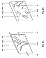
- Fig. 1 shows in cross section a portion 1 of a 3-phase High or medium voltage system with electrical Resources 20, 21 and 22.
- a facility is for Transferring large electrical power in the mega-up Gigawatt range suitable.
- the currents occurring here or voltages are in the kA or kV range.
- a typical one Plant includes multiphase generator leads, in those in the individual phases R, S, T operating currents between 5 and 30 kA and operating voltages of, for example 10 to 36 kV occur.
- Such a high voltage system Points out sections 1 in which, as a result of large power losses a strong warming occurs. Significant warming is in section 1 Contact transitions, such as switching points exposed.
- the im Inner conductor 4 formed heat is generated by heat conduction the derivatives and about natural convection and radiation delivered to the housing 3.
- the operating means 20, 21, 22 can thus electrical apparatus, Switchgear, lines, line sections o. ⁇ . which are typically high by high continuous currents Strains are loaded and correspondingly thermal Warm up.
- it is high-voltage switching devices or high current switching devices such as generator switches 20, 21, 22 are shown by way of example.
- Each generator switch 20, 21, 22 includes an inner conductor 4 for current conduction in one of the phases R, S, T and an encapsulation 3 with an encapsulation lid 3a and a z. B. trough or U-shaped encapsulation base 3b. about Encapsulation 3 flows countercurrently to ground potential, through which the magnetic fields of the current through the inner conductor 4 are shielded to the outside.
- the generator switch phases 20, 21, 22 are next to each other on one Pol frame 7 arranged.
- Fig. 1 are between adjacent and each other at least partially facing encapsulation side walls 30b in each case two radiant plates 5, 50, 51, 52 are arranged.
- the Radiant plates 5, 50, 51, 52 typically have a extensive extension parallel to the encapsulation sidewall 30b and are relatively thin along a connecting line between two adjacent encapsulations 3, 3 or phases R, S, T.
- phases R, S, T are present are supposed to be between the middle phase S and both outer phases R, T in each case at least two and preferably exactly two radiant plates 5, 50, 51, 52 are arranged be.
- T No radiant panels are installed on the outer walls of the outer phases R.
- the radiant panels 5 have one opposite the encapsulation sidewall lowered temperature, since they are not current-carrying and only by radiation from the encapsulant sidewalls 30b be heated and also good by the convection 9, 9i, 10 are cooled. This can be a heat exchange process via radiation from the side wall 30b in the direction of Radiation plate 5 take place.
- the radiant plates 5 in an air outlet area 5e in the vicinity of the capsule cover 3a in each case at least one Abwinkelungsblech 50a for leadership at least a partial air flow 9 of the rising air flow 9 in the direction of at least one of the capsule cover 3a, in particular to the associated or nearest Encapsulation cover 3a, and to the flow of this Enclosing lid 3a on.
- the primary function of the radiant panels 5 is the radiation exchange between two surfaces 30b with the same temperature, namely the Side walls 30b, increase.
- the Radiant plates 5 as a flow-directing element 5 is the Heat transfer to the flown lids 3a in addition improved. In the following, preferred embodiments discussed.
- the jet plate 5, 50, 51, 52 is ohmic to avoid Losses in the radiant plate 5, 50, 51, 52 over the Encapsulation 3; 3a, 3b electrically isolated. In general it is then the radiant plate 5, 50, 51, 52 opposite to the Encapsulation 3 isolated with respect to heat conduction. For this is the radiant panel 5 through an insulating spacer or mounting bolts 5c on an encapsulation side wall 30b supported. Preferably, there is a heat-conducting connection 5d of the radiant panel 5 to a heat sink 8 outside of the operating means 20, 21, 22.
- the radiant plate 5 may have cooling fins (not shown).
- the radiant panels 5, 50, 51, 52 may be made of any material be made, for. B. of metal and / or plastic.
- Particularly suitable is a radiant panel 5, 50, 51, 52 of aluminum sheet, surface treated is and thereby an increased IR absorption coefficient has.
- the surface should be white be to minimize heating by sunlight.
- the Suspension should be electrically insulating in the case of a metal plate be. For potential equalization but at least at one point z. B. by a metallic screw one conductive connection to the encapsulation potential available be.
- the suspension does not have to be insulating or potential-compensating Act.
- the Abwinkelungsblech 50 a with the Encapsulation cover 3a or an upper portion 5e of the encapsulation side wall 30b a positive connection 500b have (see phase T in Fig. 1).
- Fig. 1 are advantageously between two adjacent Encapsulation side walls 30b exactly two radiant plates 5, 50, 51, 52 arranged with bends 50a.
- the can Bending plates 50a each to the associated Kapselungscommunwand Be angled towards 30b.
- the number of Radiant plates 5, 50, 51, 52 determines the heat output of System. According to the calculation, the heat output can be reduced by 23% be increased if installed instead of a two radiant panels are. It is also possible between two encapsulations 3, 3 more than two radiant plates 5, 50, 51, 52 to install. Medium radiant panels can be used without bending plates be executed. Have optimization calculations but shown that it is sufficient for heat dissipation, if between two phases R, S; S, T exactly two radiant panels 5, 50, 51, 52 are attached.
- the two Radiant plates 5, 50, 51, 52 are typically substantially arranged parallel to each other. They each point one of the associated Kapselungsitwand 30b facing Inside 5a and one of the other radiant plate 5, 50, 51, 52 facing the outside 5b.
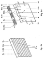
- Air guiding structures 51a for lateral deflection of the inner air flow 10 in the horizontal direction can Air guiding structures 51a for lateral deflection of the inner air flow 10 in the horizontal direction be.
- Fig. 2a are bent sideways, wing-like Baffles 51a shown.
- the baffles 51a favor an outflow to the front and / or back too with unfavorable ratio of height to width of Radiant plates 5, 50, 51, 52.
- Alternatively or additionally can generate a turbulent vertical outside airflow 9 between the two radiant plates 5, 51, 52 the outside 5b of at least one of the radiant panels 5, 51, 52 swirling structures 51b, 51c for mixing the vertical outside air flow 9 be present.
- Fig. 2b are short, preferably randomly oriented and randomly arranged wing panels 51b.
- FIG. 2c shows a horizontally corrugated corrugated sheet 51c, FIG. which also for swirling and mixing of the vertical Outside air flow 9 is used.
- the horizontally wavy Structures 51c may also be on the inside 5a of the Radiation plates 5, 52 may be present.
- the encapsulation lid 3a preferably has an edge region above the encapsulation side wall 30b a flattening 30a, wherein the Abwinkelungsblech 50a substantially is arranged flush with the flattening 30a.
- the flattening at 45 ° ⁇ 10 ° between a horizontal extent of the lid 3a or a lid shell and a vertical extent of the encapsulation sidewall 30b oriented.
- passive Cooling elements 6 are arranged, which by the ascending, guided by the radiant plate 5, 50, 51, 52 Partial air flow 9 can be flowed.
- the baffle plate 50 a can have recesses 500 c at an air-guiding outer edge in those regions where no cooling elements 6 are present on the encapsulation cover 3 a, in order to leave the vertically ascending air flow 9 i unhindered there.
- the cooling elements are preferably cooling ribs 6, which are arranged in vertical planes.
- T 1 denotes the temperature of the warmer inner air flow 10, 9i and T 2, the temperature of the less warm outside air flow 9.
- temperature differences between T 1 and T 2 can adjust up to 10 ° C.
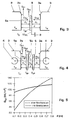
- Fig. 3 and 4 show schematically the heat balance when using a jet plate 5 or two beam plates 5.
- d distance between adjacent Kapselungsquestion 30b
- D pole distance
- Q K1 convective heat output from side wall 30b
- Q k2 convective heat output from the inside 5a of the radiant panel
- Q k3 convective heat output from the outside 5b of the radiant panel
- Q 12 radiative heat emission from side wall 30b on radiant panel
- Q WL ' heat conduction heat output from radiant panel 5 to ambient or heat sink 8
- T SP radiant panel temperature
- T U Ambient temperature
- T W sidewall temperature.
- the ambient temperature T U can be assumed to be, for example, 40 ° C.
- Theoretical calculations have shown that the radiant plates 5 lead to a temperature decrease of up to 2 ° C. at the inner conductor 4. Experimentally, 1.5 ° C were detected.
- the inventive radiant panels 5, 50, 51, 52 not only the temperature of the inner conductor 4 was lowered, but also the temperature T w of the encapsulation side wall 30b. Thus, the allowable rated current for the considered generator switch type without active cooling can be increased.
- Fig. 5 for the arrangement according to Fig. 4 with two jet plates 5 or without jet plates 5, the resulting radiated heat quantity Q 12 per area of the side wall 30b is shown as a function of the distance d between adjacent side walls 30b.
- the heat radiation through the radiant plate 5, 50, 51, 52 is significantly improved.
- the radiant panels 5, 50, 51, 52 are to be attached only if there is no longer enough solid angle below which of the encapsulation side wall 30b between two phases R, S, T an area with ambient temperature or generally a temperature lower than the wall temperature T w is visible. The attachment of the radiant plates 5, 50, 51, 52 is thus dependent on the phase or pole distance D.
- a distance d 1 between the radiant plate 5, 50, 51, 52 and the encapsulation side wall 30a or a distance d 2 between the radiant plates 5, 50, 51, 52 be chosen sufficiently large, so that a free boundary layer flow 9, 9i, 10 can train.
- the calculated minimum distance including safety margin is 40 mm. If the jet plates 5, 50, 51, 52 are not closely spaced, optimum heat transfer can not be achieved because of the reduced convection. In addition, the radiant panel 5, 50, 51, 52 should be fastened between the encapsulation side walls 30b such that a convective air flow 9, 9i, 10 remains largely unimpeded.
- the invention also includes a jet plate 5, 50, 51, 52 for an installation section 1 and an electrical switchgear, in particular a high or medium voltage switchgear with such a plant section 1 as before described.
- the invention allows resources 20, 21, 22 are operated at higher rated currents and / or plant sections 1 are built more compact.
Landscapes
- Engineering & Computer Science (AREA)
- Power Engineering (AREA)
- Cooling Or The Like Of Electrical Apparatus (AREA)
- Patch Boards (AREA)
- Gas-Insulated Switchgears (AREA)
- Installation Of Bus-Bars (AREA)
- Devices For Blowing Cold Air, Devices For Blowing Warm Air, And Means For Preventing Water Condensation In Air Conditioning Units (AREA)
Abstract
Description
- Fig. 1
- zeigt im Querschnitt eine 3-phasige Generatorschalter-Anordnung mit erfindungsgemäss abgewinkelten Strahlblechen zwischen den Phasen;
- Fig. 2a-2d
- zeigen Ausführungsbeispiele für die Strahlbleche;
- Fig. 3, 4
- zeigen schematische Darstellungen der Wärmebilanz mit einem Strahlblech oder zwei Strahlblechen zwischen zwei Phasen; und
- Fig. 5
- zeigt Berechnungen der Wärmebilanz mit und ohne Strahlblech.
- 1
- 3-Phasen-Generatorschalter, gekapselte dauerstromführende elektrische Betriebsmittel
- 20, 21, 22
- Generatorschalter, Schaltgerät, Phasen; R, S, T
- 3
- Gehäuse, Kapselung, Induktionsstromleiter
- 3a
- Kapselungsdeckel
- 30a
- Abflachung an Kapselungsdeckel
- 3b
- Kapselungsunterteil, Wanne
- 30b
- der Nachbarphase zugewandte Kapselungsseitenwand
- 4
- Innenleiter, Hochstromleiter
- 5, 50, 51, 52
- Strahlplatte mit Winkelblech
- 5a
- Innenseite der Strahlplatte
- 5b
- Aussenseite der Strahlplatte
- 5c
- isolierende Montagebolzen, Distanzhalter
- 5d
- wärmeleitender Anschluss an Wärmesenke
- 5e
- oberer Bereich der Strahlplatte, Luftaustrittsbereich
- 50
- Strahlplatte ohne Luftführungsstrukturen
- 50a
- Abwinkelung, Winkelblech, Anströmblech
- 500b
- formschlüssige Verbindung
- 500c
- Ausnehmungen
- 51
- Strahlplatte mit Luftführungsblechen
- 52
- Strahlplatte mit Verwirbelungsblechen
- 51a
- seitliches Ablenkblech, Zweiflügelblech
- 51b
- Verwirbelungsbleche, Einflügelblech
- 51c
- Luftführungsbleche, Verwirbelungsblech
- 6
- Kühlrippen
- 7
- Polrahmen, Tragrahmen
- 8
- Wärmesenke
- 9, 9i
- vertikale Luftströmung
- 10
- horizontale Luftströmung
- d, d1, d2
- Abstände zwischen Kapselungsseitenwänden und/oder Strahlplatten
- D
- Polabstand, Abstand zwischen den Phasen
- QK, Qk1, Qk2, Qk3
- konvektive Wärmeabgabe
- Q12
- Strahlungswärmeabgabe, von Seitenwand abgestrahlte Wärmemenge pro Fläche
- QWL'
- Wärmeleitungswärmeabgabe
- T1, T2
- Lufttemperaturen
- TSP
- Strahlplattentemperatur
- TU
- Umgebungstemperatur
- TW
- Wandtemperatur
Claims (11)
- Abschnitt (1) einer elektrischen Hochspannungsanlage zum Führen und/oder Schalten hoher Ströme und/oder Spannungen, umfassend elektrische Betriebsmittel (20, 21, 22) für mindestens drei Phasen (R, S, T), wobei die Betriebsmittel (20, 21, 22) in Kapselungen (3) angeordnet und mit Kapselungsdeckeln (3a) abgedeckt sind und benachbarte Kapselungen (3) über jeweils mindestens eine Kapselungsseitenwand (30b) miteinander in Wärmeaustausch stehen, wobei ferner zwischen zwei Kapselungsseitenwänden (30b) mindestens zwei Zwischenplatten angeordnet sind, die zur Wärmeaufnahme von mindestens einer Kapselungsseitenwand (30b) und zur Wärmeabgabe an einen zwischen den Kapselungsseitenwänden (30b) vertikal aufsteigenden Luftstrom (9) dienen, dadurch gekennzeichnet, dass mindestens eine der Zwischenplatten eine strömungslenkende Strahlplatte (5, 50, 51, 52) ist, die in einem Luftaustrittsbereich (5e) in der Nähe der Kapselungsdeckel (3a) mindestens ein Abwinkelungsblech (50a) zur Führung mindestens eines Teilluftstroms (9) des aufsteigenden Luftstroms (9) in Richtung auf mindestens einen der Kapselungsdeckel (3a) und zur Anströmung des Kapselungsdeckels (3a) aufweist.
- Der Anlagenabschnitt (1) nach Anspruch 1, dadurch gekennzeichnet, dass die Strahlplatte oder Strahlplatten (5, 50, 51, 52)a) zur Vermeidung ohmscher Verluste gegenüber der Kapselung (3) elektrisch isoliert ist oder sind und ein Potentialausgleich vorhanden ist und/oderb) gegenüber der Kapselung (3) bezüglich Wärmeleitung isoliert ist oder sind und/oderc) zur zusätzlichen Wärmeabgabe durch Wärmeleitung (Qwl') mit einer Wärmesenke (8) thermisch leitend verbunden ist oder sind.
- Der Anlagenabschnitt (1) nach einem der vorangehenden Ansprüche, dadurch gekennzeichnet, dass zur Blockierung eines vertikal aufsteigenden Innenluftstroms (9i) zwischen der Kapselungsseitenwand (30b) und der zugehörigen Strahlplatte (5, 50, 51, 52) das Abwinkelungsblech (50a) mit dem Kapselungsdeckel (3a) oder einem oberen Bereich 5e der Kapselungsseitenwand (30b) eine formschlüssige Verbindung (500b) aufweist.
- Der Anlagenabschnitt (1) nach einem der vorangehenden Ansprüche, dadurch gekennzeichnet, dassa) zwischen zwei benachbarten Kapselungsseitenwänden (30b) genau zwei Strahlplatten (5, 50, 51, 52) angeordnet sind, die jeweils eine der zugehörigen Kapselungsseitenwand (30) zugewandte Innenseite (5a) und eine der anderen Strahlplatte (5, 50, 51, 52) zugewandte Aussenseite (5b) aufweisen undb) jede Strahlplatte (5, 50, 51, 52) ein zur zugehörigen Kapselungsseitenwand (30b) hin abgewinkeltes Abwinkelungsblech (50a) aufweist.
- Der Anlagenabschnitt (1) nach Anspruch 4, dadurch gekennzeichnet, dassa) zur Erzeugung eines horizontalen Innenluftstroms (10) zwischen der Kapselungsseitenwand (30b) und mindestens einer der Strahlplatten (5, 51, 52) auf der Innenseite (5a) der Strahlplatte (5, 51, 52) Luftführungsstrukturen (51a) zur seitlichen Ablenkung des horizontalen Innenluftstroms (10) vorhanden sind und/oderb) zur Erzeugung eines vertikalen Aussenluftstroms (9) zwischen beiden Strahlplatten (5, 51, 52) auf der Aussenseite (5b) mindestens einer der Strahlplatten (5, 51, 52) Verwirbelungsstrukturen (51b, 51c) zur Durchmischung des vertikalen Aussenluftstroms (9) vorhanden sind.
- Der Anlagenabschnitt (1) nach einem der vorangehenden Ansprüche, dadurch gekennzeichnet, dassa) die Kapselungsdeckel (3a) in einem Randbereich oberhalb der Kapselungsseitenwand (30b) eine Abflachung (30a) aufweisen und die jeweiligen Abwinkelungsbleche (50a) im wesentlichen fluchtend zur Abflachung (30a) angeordnet sind und/oderb) auf den Kapselungsdeckeln (3a), insbesondere auf einer Abflachung (30a) der Kapselungsdeckel (3a), passive Kühlelemente (6) angeordnet sind, die durch den aufsteigenden, von den Strahlplatten (5, 50, 51, 52) geführten Teilluftstrom (9) anströmbar sind.
- Der Anlagenabschnitt (1) nach Anspruch 6, dadurch gekennzeichnet, dassa) die Abwinkelungsbleche (50a) an einer luftführenden Aussenkante Ausnehmungen (500c) in solchen Bereichen aufweisen, wo keine Kühlelemente (6) auf den Kapselungsdeckeln (3a) vorhanden sind, um den dort vertikal aufsteigenden Luftstrom (9i) unbehindert zu lassen und/oderb) auf den Kapselungsdeckeln (3a) angeordnete Kühlelemente Kühlrippen (6) aufweisen, die in vertikalen Ebenen angeordnet sind.
- Der Anlagenabschnitt (1) nach einem der vorangehenden Ansprüche, dadurch gekennzeichnet, dassa) zwischen den Strahlplatten (5, 50, 51, 52) und den zugehörigen Kapselungsseitenwänden (30a) und/oder zwischen den Strahlplatten (5, 50, 51, 52) ein hinreichender Abstand (d1, d2) gewählt ist, so dass sich eine freie Grenzschichtströmung (9, 9i, 10) ausbilden kann und/oderb) die Strahlplatten (5, 50, 51, 52) so zwischen den Kapselungsseitenwänden (3a) befestigt sind, dass eine konvektive Luftströmung (9, 9i, 10) weitgehend unbehindert ist.
- Der Anlagenabschnitt (1) nach einem der vorangehenden Ansprüche, dadurch gekennzeichnet, dassa) die Strahlplatten (5, 50, 51, 52) Metallplatten, insbesondere weiss gefärbte Aluminiumbleche, mit einer elektrisch isolierenden Aufhängung und/oder Kunststoffplatten sind und/oderb) drei Phasen (R, S, T) vorhanden sind und zwischen der mittleren Phase (S) und beiden äusseren Phasen (R, T) jeweils zwei Strahlplatten (5, 50, 51, 52) angeordnet sind und/oderc) die Betriebsmittel (20, 21, 22) Hochstromschaltgeräte (20, 21, 22), insbesondere Generatorschalter (20, 21, 22), oder Hochspannungsschaltgeräte sind.
- Strahlplatte für einen Anlagenabschnitt (1) gemäss einem der vorangehenden Ansprüche.
- Elektrische Anlage, insbesondere Hoch- oder Mittelspannungsschaltanlage, gekennzeichnet durch einen Anlagenabschnitt (1) gemäss einem der vorangehenden Ansprüche.
Priority Applications (5)
| Application Number | Priority Date | Filing Date | Title |
|---|---|---|---|
| EP03405592A EP1507323B1 (de) | 2003-08-13 | 2003-08-13 | Gekapselte Schaltgeräte mit wärmeabführenden Elementen |
| US10/913,465 US7272003B2 (en) | 2003-08-13 | 2004-08-09 | Encapsulated switching devices having heat emission elements |
| RU2004124622/09A RU2328798C2 (ru) | 2003-08-13 | 2004-08-12 | Заключенные в корпус коммутационные аппараты с теплоотражающими элементами |
| CN200410056670.1A CN1581618B (zh) | 2003-08-13 | 2004-08-13 | 开关装置和用于这种装置的辐射板 |
| JP2004236064A JP2005065496A (ja) | 2003-08-13 | 2004-08-13 | 熱放出要素を有する保護囲い付きスイッチング装置 |
Applications Claiming Priority (1)
| Application Number | Priority Date | Filing Date | Title |
|---|---|---|---|
| EP03405592A EP1507323B1 (de) | 2003-08-13 | 2003-08-13 | Gekapselte Schaltgeräte mit wärmeabführenden Elementen |
Publications (2)
| Publication Number | Publication Date |
|---|---|
| EP1507323A1 true EP1507323A1 (de) | 2005-02-16 |
| EP1507323B1 EP1507323B1 (de) | 2012-10-03 |
Family
ID=33560913
Family Applications (1)
| Application Number | Title | Priority Date | Filing Date |
|---|---|---|---|
| EP03405592A Expired - Lifetime EP1507323B1 (de) | 2003-08-13 | 2003-08-13 | Gekapselte Schaltgeräte mit wärmeabführenden Elementen |
Country Status (5)
| Country | Link |
|---|---|
| US (1) | US7272003B2 (de) |
| EP (1) | EP1507323B1 (de) |
| JP (1) | JP2005065496A (de) |
| CN (1) | CN1581618B (de) |
| RU (1) | RU2328798C2 (de) |
Cited By (3)
| Publication number | Priority date | Publication date | Assignee | Title |
|---|---|---|---|---|
| WO2008098866A2 (de) | 2007-02-16 | 2008-08-21 | Siemens Aktiengesellschaft | Elektroenergieübertragungsanordnung mit einem kapselungsgehäuse |
| RU2456783C1 (ru) * | 2011-03-30 | 2012-07-20 | Открытое акционерное общество "Государственный Рязанский приборный завод" (ОАО "ГРПЗ") | Экранированный корпус прибора с охлаждением |
| CN106786040A (zh) * | 2016-11-30 | 2017-05-31 | 国网山东省电力公司东明县供电公司 | 防水防雨电表箱及电表设置结构 |
Families Citing this family (16)
| Publication number | Priority date | Publication date | Assignee | Title |
|---|---|---|---|---|
| ATE441196T1 (de) * | 2004-11-16 | 2009-09-15 | Abb Research Ltd | Hochspannungsleistungsschalter mit kühlung |
| EP1667300B1 (de) * | 2004-12-03 | 2014-03-19 | ABB Research Ltd. | Hochspannungsanlage und Hochleistungsschalter mit Kühlung |
| US20080148642A1 (en) * | 2006-09-29 | 2008-06-26 | Alain Herve Mathieu | Arc resistant switchgear door and frame assembly, through the door racking system, and air cooling and ventilation system |
| US8547675B2 (en) * | 2006-11-07 | 2013-10-01 | Hamilton Sundstrand Corporation | Solid state power controller with lightning protection |
| DE102007022371A1 (de) * | 2007-05-07 | 2008-11-13 | Siemens Ag | Schottvorrichtung für eine Stromverteilereinheit |
| ATE501516T1 (de) * | 2008-08-20 | 2011-03-15 | Abb Technology Ag | Hochspannungsschalter mit kühlung |
| ATE534175T1 (de) * | 2009-07-27 | 2011-12-15 | Abb Research Ltd | Leistungsschaltwerk |
| FR2951859B1 (fr) * | 2009-10-26 | 2012-12-21 | Areva T & D Sas | Procede de refroidissement par caloducs integres d'un appareil electrique moyenne tension et systeme utilisant ce procede |
| JP5100786B2 (ja) * | 2010-05-10 | 2012-12-19 | シャープ株式会社 | 画像形成装置 |
| WO2014106905A1 (ja) * | 2013-01-07 | 2014-07-10 | 三菱電機株式会社 | 遮断器用箱体および電力用開閉装置 |
| SG2013069224A (en) * | 2013-09-13 | 2015-04-29 | Rockwell Automation Asia Pacific Business Ctr Pte Ltd | Motor drive with inherent power isolation |
| CN108879360B (zh) * | 2018-06-21 | 2020-08-14 | 向荣集团有限公司 | 一种静止无功发生器电容柜支座及静止无功发生器 |
| CN110380351B (zh) * | 2019-07-29 | 2020-07-07 | 国家电网有限公司 | 一种散热性好且防水的精密仪器用电力柜 |
| CN114379393A (zh) * | 2022-01-19 | 2022-04-22 | 深圳威迈斯新能源股份有限公司 | 一种复用金属基电路板的冷却流道结构及车载充电机 |
| EP4539277A1 (de) * | 2023-10-13 | 2025-04-16 | Abb Schweiz Ag | Schalteinrichtung |
| EP4560674A1 (de) * | 2023-11-21 | 2025-05-28 | Abb Schweiz Ag | Schaltanlage |
Citations (3)
| Publication number | Priority date | Publication date | Assignee | Title |
|---|---|---|---|---|
| GB2085238A (en) * | 1980-10-14 | 1982-04-21 | Bicc Ltd | Electrical power cable installations |
| EP1022831A1 (de) * | 1998-12-24 | 2000-07-26 | ABB Hochspannungstechnik AG | Abschnitt einer Hochspannungsanlage mit Kühlmitteln |
| US6236562B1 (en) * | 1998-12-24 | 2001-05-22 | Asea Brown Boveri Ag | Section of a high-voltage system having cooling means and including a conductor |
Family Cites Families (9)
| Publication number | Priority date | Publication date | Assignee | Title |
|---|---|---|---|---|
| DE19804902C2 (de) * | 1998-02-07 | 2003-09-04 | Rittal Gmbh & Co Kg | Schaltschrank |
| US6088225A (en) * | 1998-03-17 | 2000-07-11 | Northern Telecom Limited | Cabinet with enhanced convection cooling |
| US5995368A (en) * | 1998-10-20 | 1999-11-30 | Nortel Networks Corporation | Air flow distribution device for shelf-based circuit cards |
| JP3820809B2 (ja) * | 1999-07-27 | 2006-09-13 | 三菱電機株式会社 | スイッチギヤの断路装置 |
| US6400567B1 (en) * | 2000-10-19 | 2002-06-04 | Fujitsu Network Communications, Inc. | Equipment enclosure having separate compartments cooled by separate cooling airflows |
| US6417443B1 (en) * | 2001-03-29 | 2002-07-09 | Eaton Corporation | Exhaust chamber for arc resistant cabinets |
| AU2002306161A1 (en) * | 2001-06-12 | 2002-12-23 | Liebert Corporation | Single or dual buss thermal transfer system |
| US6999305B1 (en) * | 2002-08-27 | 2006-02-14 | Delaware Capital Formation, Inc. | Modular electrical distribution system |
| DE50304860D1 (de) * | 2003-07-11 | 2006-10-12 | Abb Research Ltd | Hochleistungsschalter mit Kühlrippenanordnung |
-
2003
- 2003-08-13 EP EP03405592A patent/EP1507323B1/de not_active Expired - Lifetime
-
2004
- 2004-08-09 US US10/913,465 patent/US7272003B2/en not_active Expired - Fee Related
- 2004-08-12 RU RU2004124622/09A patent/RU2328798C2/ru not_active IP Right Cessation
- 2004-08-13 CN CN200410056670.1A patent/CN1581618B/zh not_active Expired - Fee Related
- 2004-08-13 JP JP2004236064A patent/JP2005065496A/ja not_active Withdrawn
Patent Citations (3)
| Publication number | Priority date | Publication date | Assignee | Title |
|---|---|---|---|---|
| GB2085238A (en) * | 1980-10-14 | 1982-04-21 | Bicc Ltd | Electrical power cable installations |
| EP1022831A1 (de) * | 1998-12-24 | 2000-07-26 | ABB Hochspannungstechnik AG | Abschnitt einer Hochspannungsanlage mit Kühlmitteln |
| US6236562B1 (en) * | 1998-12-24 | 2001-05-22 | Asea Brown Boveri Ag | Section of a high-voltage system having cooling means and including a conductor |
Cited By (7)
| Publication number | Priority date | Publication date | Assignee | Title |
|---|---|---|---|---|
| WO2008098866A2 (de) | 2007-02-16 | 2008-08-21 | Siemens Aktiengesellschaft | Elektroenergieübertragungsanordnung mit einem kapselungsgehäuse |
| DE102007008591A1 (de) * | 2007-02-16 | 2008-08-21 | Siemens Ag | Elektroenergieübertragungsanordnung mit einem Kapselungsgehäuse |
| WO2008098866A3 (de) * | 2007-02-16 | 2008-11-13 | Siemens Ag | Elektroenergieübertragungsanordnung mit einem kapselungsgehäuse |
| CN101617451B (zh) * | 2007-02-16 | 2013-01-02 | 西门子公司 | 带有封装壳体的电能传输设备 |
| RU2456783C1 (ru) * | 2011-03-30 | 2012-07-20 | Открытое акционерное общество "Государственный Рязанский приборный завод" (ОАО "ГРПЗ") | Экранированный корпус прибора с охлаждением |
| CN106786040A (zh) * | 2016-11-30 | 2017-05-31 | 国网山东省电力公司东明县供电公司 | 防水防雨电表箱及电表设置结构 |
| CN106786040B (zh) * | 2016-11-30 | 2018-06-19 | 国网山东省电力公司东明县供电公司 | 防水防雨电表箱及电表设置结构 |
Also Published As
| Publication number | Publication date |
|---|---|
| CN1581618A (zh) | 2005-02-16 |
| RU2328798C2 (ru) | 2008-07-10 |
| RU2004124622A (ru) | 2006-01-27 |
| EP1507323B1 (de) | 2012-10-03 |
| US7272003B2 (en) | 2007-09-18 |
| CN1581618B (zh) | 2010-05-26 |
| JP2005065496A (ja) | 2005-03-10 |
| US20050063154A1 (en) | 2005-03-24 |
Similar Documents
| Publication | Publication Date | Title |
|---|---|---|
| EP1507323B1 (de) | Gekapselte Schaltgeräte mit wärmeabführenden Elementen | |
| DE102006024682B4 (de) | Geräteschrank mit zwei Kühlkanälen und Anordnung mit dem Geräteschrank | |
| EP0904676B1 (de) | Geräteschrank für elektrische und elektronische systeme | |
| DE68920513T2 (de) | Wechselrichtervorrichtung. | |
| EP0297308B1 (de) | Schaltschrank | |
| EP1428419B1 (de) | Aktiv aussengekühltes gehäuse mit zumindest einem wärmeverlustleistungserzeugenden elektronikbaustein | |
| EP2949191B1 (de) | Wechselrichter mit zweiteiligem gehäuse | |
| EP1496534B1 (de) | Hochleistungsschalter mit Kühlrippenanordnung | |
| EP2291064B1 (de) | Elektronische Einheit mit Kühlrippen | |
| DE102018212978A1 (de) | Ladestation zum Laden eines Elektrofahrzeugs | |
| EP2346052B1 (de) | Gehäuse für eine elektrische Maschine | |
| DE102017119867A1 (de) | Leistungsteil | |
| DE19739309A1 (de) | Stromversorgungseinheit | |
| EP3490351B1 (de) | Niederspannungsschaltgerät mit einer definierten kühlanordnung | |
| DE102022108833B3 (de) | Batterieeinrichtung zur geführten Kühlung von Batteriezellen und einer Stromschiene und Verfahren zum Betrieb einer Batterieeinrichtung zur geführten Kühlung von Batteriezellen und einer Stromschiene | |
| DE3784016T2 (de) | Metallgekapselte schaltanlage. | |
| EP1022830B1 (de) | Abschnitt einer Hochspannungsanlage mit Kühlmitteln | |
| EP4016783A1 (de) | Ladegerät mit ladeelektronikeinheit und kühlluftführungsstruktur | |
| EP0666627A1 (de) | Lichtbogenabsorber | |
| WO2024193922A1 (de) | Kühlvorrichtung und gehäuse für eine schaltanordnung sowie schaltanordnung | |
| DE2833127C2 (de) | Gekapseltes, durch Luftumwälzung gekühltes Schaltfeld | |
| EP4437641A1 (de) | Elektromotor | |
| DE102023112906B3 (de) | Wechselrichter mit geschlossenem Kühlkanal | |
| DE202017101238U1 (de) | Dachumrichter mit Sonnenschild | |
| DE102015121235A1 (de) | Schaltanlagenkühlanordnung |
Legal Events
| Date | Code | Title | Description |
|---|---|---|---|
| PUAI | Public reference made under article 153(3) epc to a published international application that has entered the european phase |
Free format text: ORIGINAL CODE: 0009012 |
|
| AK | Designated contracting states |
Kind code of ref document: A1 Designated state(s): AT BE BG CH CY CZ DE DK EE ES FI FR GB GR HU IE IT LI LU MC NL PT RO SE SI SK TR |
|
| AX | Request for extension of the european patent |
Extension state: AL LT LV MK |
|
| 17P | Request for examination filed |
Effective date: 20050716 |
|
| AKX | Designation fees paid |
Designated state(s): AT BE BG CH CY CZ DE DK EE ES FI FR GB GR HU IE IT LI LU MC NL PT RO SE SI SK TR |
|
| GRAP | Despatch of communication of intention to grant a patent |
Free format text: ORIGINAL CODE: EPIDOSNIGR1 |
|
| RIN1 | Information on inventor provided before grant (corrected) |
Inventor name: SCHOENEMANN, THOMAS Inventor name: LAKMER, MARTIN Inventor name: YE, XIANGYANG Inventor name: PLEINES, MARIANNE Inventor name: MAUROUX, JEAN-CLAUDE |
|
| GRAS | Grant fee paid |
Free format text: ORIGINAL CODE: EPIDOSNIGR3 |
|
| GRAA | (expected) grant |
Free format text: ORIGINAL CODE: 0009210 |
|
| RIN1 | Information on inventor provided before grant (corrected) |
Inventor name: LAKNER, MARTIN Inventor name: SCHOENEMANN, THOMAS Inventor name: PLEINES, MARIANNE Inventor name: MAUROUX, JEAN-CLAUDE Inventor name: YE, XIANGYANG |
|
| AK | Designated contracting states |
Kind code of ref document: B1 Designated state(s): AT BE BG CH CY CZ DE DK EE ES FI FR GB GR HU IE IT LI LU MC NL PT RO SE SI SK TR |
|
| REG | Reference to a national code |
Ref country code: GB Ref legal event code: FG4D Free format text: NOT ENGLISH |
|
| REG | Reference to a national code |
Ref country code: CH Ref legal event code: EP Ref country code: AT Ref legal event code: REF Ref document number: 578364 Country of ref document: AT Kind code of ref document: T Effective date: 20121015 |
|
| REG | Reference to a national code |
Ref country code: IE Ref legal event code: FG4D Free format text: LANGUAGE OF EP DOCUMENT: GERMAN |
|
| REG | Reference to a national code |
Ref country code: DE Ref legal event code: R096 Ref document number: 50314521 Country of ref document: DE Effective date: 20121129 |
|
| PG25 | Lapsed in a contracting state [announced via postgrant information from national office to epo] |
Ref country code: SI Free format text: LAPSE BECAUSE OF FAILURE TO SUBMIT A TRANSLATION OF THE DESCRIPTION OR TO PAY THE FEE WITHIN THE PRESCRIBED TIME-LIMIT Effective date: 20121003 |
|
| REG | Reference to a national code |
Ref country code: NL Ref legal event code: VDEP Effective date: 20121003 |
|
| PG25 | Lapsed in a contracting state [announced via postgrant information from national office to epo] |
Ref country code: SE Free format text: LAPSE BECAUSE OF FAILURE TO SUBMIT A TRANSLATION OF THE DESCRIPTION OR TO PAY THE FEE WITHIN THE PRESCRIBED TIME-LIMIT Effective date: 20121003 Ref country code: ES Free format text: LAPSE BECAUSE OF FAILURE TO SUBMIT A TRANSLATION OF THE DESCRIPTION OR TO PAY THE FEE WITHIN THE PRESCRIBED TIME-LIMIT Effective date: 20130114 Ref country code: NL Free format text: LAPSE BECAUSE OF FAILURE TO SUBMIT A TRANSLATION OF THE DESCRIPTION OR TO PAY THE FEE WITHIN THE PRESCRIBED TIME-LIMIT Effective date: 20121003 Ref country code: FI Free format text: LAPSE BECAUSE OF FAILURE TO SUBMIT A TRANSLATION OF THE DESCRIPTION OR TO PAY THE FEE WITHIN THE PRESCRIBED TIME-LIMIT Effective date: 20121003 |
|
| PG25 | Lapsed in a contracting state [announced via postgrant information from national office to epo] |
Ref country code: PT Free format text: LAPSE BECAUSE OF FAILURE TO SUBMIT A TRANSLATION OF THE DESCRIPTION OR TO PAY THE FEE WITHIN THE PRESCRIBED TIME-LIMIT Effective date: 20130204 Ref country code: CY Free format text: LAPSE BECAUSE OF FAILURE TO SUBMIT A TRANSLATION OF THE DESCRIPTION OR TO PAY THE FEE WITHIN THE PRESCRIBED TIME-LIMIT Effective date: 20121003 Ref country code: GR Free format text: LAPSE BECAUSE OF FAILURE TO SUBMIT A TRANSLATION OF THE DESCRIPTION OR TO PAY THE FEE WITHIN THE PRESCRIBED TIME-LIMIT Effective date: 20130104 |
|
| PG25 | Lapsed in a contracting state [announced via postgrant information from national office to epo] |
Ref country code: SK Free format text: LAPSE BECAUSE OF FAILURE TO SUBMIT A TRANSLATION OF THE DESCRIPTION OR TO PAY THE FEE WITHIN THE PRESCRIBED TIME-LIMIT Effective date: 20121003 Ref country code: CZ Free format text: LAPSE BECAUSE OF FAILURE TO SUBMIT A TRANSLATION OF THE DESCRIPTION OR TO PAY THE FEE WITHIN THE PRESCRIBED TIME-LIMIT Effective date: 20121003 Ref country code: BG Free format text: LAPSE BECAUSE OF FAILURE TO SUBMIT A TRANSLATION OF THE DESCRIPTION OR TO PAY THE FEE WITHIN THE PRESCRIBED TIME-LIMIT Effective date: 20130103 Ref country code: DK Free format text: LAPSE BECAUSE OF FAILURE TO SUBMIT A TRANSLATION OF THE DESCRIPTION OR TO PAY THE FEE WITHIN THE PRESCRIBED TIME-LIMIT Effective date: 20121003 Ref country code: EE Free format text: LAPSE BECAUSE OF FAILURE TO SUBMIT A TRANSLATION OF THE DESCRIPTION OR TO PAY THE FEE WITHIN THE PRESCRIBED TIME-LIMIT Effective date: 20121003 |
|
| PLBE | No opposition filed within time limit |
Free format text: ORIGINAL CODE: 0009261 |
|
| STAA | Information on the status of an ep patent application or granted ep patent |
Free format text: STATUS: NO OPPOSITION FILED WITHIN TIME LIMIT |
|
| PG25 | Lapsed in a contracting state [announced via postgrant information from national office to epo] |
Ref country code: RO Free format text: LAPSE BECAUSE OF FAILURE TO SUBMIT A TRANSLATION OF THE DESCRIPTION OR TO PAY THE FEE WITHIN THE PRESCRIBED TIME-LIMIT Effective date: 20121003 Ref country code: IT Free format text: LAPSE BECAUSE OF FAILURE TO SUBMIT A TRANSLATION OF THE DESCRIPTION OR TO PAY THE FEE WITHIN THE PRESCRIBED TIME-LIMIT Effective date: 20121003 |
|
| 26N | No opposition filed |
Effective date: 20130704 |
|
| PGFP | Annual fee paid to national office [announced via postgrant information from national office to epo] |
Ref country code: DE Payment date: 20130821 Year of fee payment: 11 |
|
| REG | Reference to a national code |
Ref country code: DE Ref legal event code: R097 Ref document number: 50314521 Country of ref document: DE Effective date: 20130704 |
|
| PGFP | Annual fee paid to national office [announced via postgrant information from national office to epo] |
Ref country code: FR Payment date: 20130823 Year of fee payment: 11 |
|
| BERE | Be: lapsed |
Owner name: ABB RESEARCH LTD. Effective date: 20130831 |
|
| REG | Reference to a national code |
Ref country code: CH Ref legal event code: PL |
|
| GBPC | Gb: european patent ceased through non-payment of renewal fee |
Effective date: 20130813 |
|
| PG25 | Lapsed in a contracting state [announced via postgrant information from national office to epo] |
Ref country code: LI Free format text: LAPSE BECAUSE OF NON-PAYMENT OF DUE FEES Effective date: 20130831 Ref country code: MC Free format text: LAPSE BECAUSE OF FAILURE TO SUBMIT A TRANSLATION OF THE DESCRIPTION OR TO PAY THE FEE WITHIN THE PRESCRIBED TIME-LIMIT Effective date: 20121003 Ref country code: CH Free format text: LAPSE BECAUSE OF NON-PAYMENT OF DUE FEES Effective date: 20130831 |
|
| REG | Reference to a national code |
Ref country code: IE Ref legal event code: MM4A |
|
| PG25 | Lapsed in a contracting state [announced via postgrant information from national office to epo] |
Ref country code: BE Free format text: LAPSE BECAUSE OF NON-PAYMENT OF DUE FEES Effective date: 20130831 |
|
| PG25 | Lapsed in a contracting state [announced via postgrant information from national office to epo] |
Ref country code: IE Free format text: LAPSE BECAUSE OF NON-PAYMENT OF DUE FEES Effective date: 20130813 Ref country code: GB Free format text: LAPSE BECAUSE OF NON-PAYMENT OF DUE FEES Effective date: 20130813 |
|
| REG | Reference to a national code |
Ref country code: AT Ref legal event code: MM01 Ref document number: 578364 Country of ref document: AT Kind code of ref document: T Effective date: 20130813 |
|
| PG25 | Lapsed in a contracting state [announced via postgrant information from national office to epo] |
Ref country code: AT Free format text: LAPSE BECAUSE OF NON-PAYMENT OF DUE FEES Effective date: 20130813 |
|
| REG | Reference to a national code |
Ref country code: DE Ref legal event code: R119 Ref document number: 50314521 Country of ref document: DE |
|
| REG | Reference to a national code |
Ref country code: DE Ref legal event code: R119 Ref document number: 50314521 Country of ref document: DE Effective date: 20150303 |
|
| REG | Reference to a national code |
Ref country code: FR Ref legal event code: ST Effective date: 20150430 |
|
| PG25 | Lapsed in a contracting state [announced via postgrant information from national office to epo] |
Ref country code: TR Free format text: LAPSE BECAUSE OF FAILURE TO SUBMIT A TRANSLATION OF THE DESCRIPTION OR TO PAY THE FEE WITHIN THE PRESCRIBED TIME-LIMIT Effective date: 20121003 |
|
| PG25 | Lapsed in a contracting state [announced via postgrant information from national office to epo] |
Ref country code: LU Free format text: LAPSE BECAUSE OF NON-PAYMENT OF DUE FEES Effective date: 20130813 Ref country code: DE Free format text: LAPSE BECAUSE OF NON-PAYMENT OF DUE FEES Effective date: 20150303 Ref country code: HU Free format text: LAPSE BECAUSE OF FAILURE TO SUBMIT A TRANSLATION OF THE DESCRIPTION OR TO PAY THE FEE WITHIN THE PRESCRIBED TIME-LIMIT; INVALID AB INITIO Effective date: 20030813 |
|
| PG25 | Lapsed in a contracting state [announced via postgrant information from national office to epo] |
Ref country code: FR Free format text: LAPSE BECAUSE OF NON-PAYMENT OF DUE FEES Effective date: 20140901 |