EP4539277A1 - Schalteinrichtung - Google Patents
Schalteinrichtung Download PDFInfo
- Publication number
- EP4539277A1 EP4539277A1 EP23203556.8A EP23203556A EP4539277A1 EP 4539277 A1 EP4539277 A1 EP 4539277A1 EP 23203556 A EP23203556 A EP 23203556A EP 4539277 A1 EP4539277 A1 EP 4539277A1
- Authority
- EP
- European Patent Office
- Prior art keywords
- component
- guiding vanes
- guiding
- guide structure
- air guide
- Prior art date
- Legal status (The legal status is an assumption and is not a legal conclusion. Google has not performed a legal analysis and makes no representation as to the accuracy of the status listed.)
- Pending
Links
Images
Classifications
-
- H—ELECTRICITY
- H02—GENERATION; CONVERSION OR DISTRIBUTION OF ELECTRIC POWER
- H02B—BOARDS, SUBSTATIONS OR SWITCHING ARRANGEMENTS FOR THE SUPPLY OR DISTRIBUTION OF ELECTRIC POWER
- H02B1/00—Frameworks, boards, panels, desks, casings; Details of substations or switching arrangements
- H02B1/56—Cooling; Ventilation
-
- H—ELECTRICITY
- H02—GENERATION; CONVERSION OR DISTRIBUTION OF ELECTRIC POWER
- H02B—BOARDS, SUBSTATIONS OR SWITCHING ARRANGEMENTS FOR THE SUPPLY OR DISTRIBUTION OF ELECTRIC POWER
- H02B13/00—Arrangement of switchgear in which switches are enclosed in, or structurally associated with, a casing, e.g. cubicle
-
- H—ELECTRICITY
- H02—GENERATION; CONVERSION OR DISTRIBUTION OF ELECTRIC POWER
- H02G—INSTALLATION OF ELECTRIC CABLES OR LINES, OR OF COMBINED OPTICAL AND ELECTRIC CABLES OR LINES
- H02G5/00—Installations of bus-bars
- H02G5/10—Cooling
Definitions
- busbars heat up due to the passage of electrical current via Joule heating.
- the first component is a busbar.
- the first component is not oriented horizontally or vertically, but is at an angle.
- one or more of the plurality of guiding vanes are parallel to the first surface of the first component.
- the second surface of the first component is parallel to the first surface of the first component.
- one or more of the plurality of guiding vanes are parallel to the second surface of the first component.
- switchgear comprises:
- the second component is a busbar.
- the first component is adjacent to and parallel to the second component, for example two busbars one above the other with an air gap between them.
- the second component is not oriented horizontally or vertically, but is at an angle.
- one or more of the plurality of guiding vanes are parallel to the first surface of the second component.
- the first surface of the second component is flat.
- one or more of the plurality of guiding vanes are configured to direct air to enter the air guide structure at the entrance then flow tangentially to a second surface of the second component and then leave the air guide structure at the exit.
- the second surface of the second component is flat.
- one or more of the plurality of guiding vanes are parallel to the second surface of the second component.
- the upper outer guiding vane is located above the second component.
- the plurality of guiding vanes comprises a lower outer guiding vane located below the first component, and the lower outer guiding vane extends from the entrance of the guide structure to the exit of the air guide structure.
- the lower outer guiding vane is located below the second component.
- the plurality of guiding vanes comprises one or more rear guiding vanes located at the exit of the air guide structure.
- the one or more rear guiding vanes comprises a plurality of rear guiding vanes, and a honey comb structure is formed at least in part from the plurality of rear guiding vanes.
- one or more of the plurality of guiding vanes are airfoils.
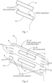
- Fig. 2 relates to a new air guiding structure that is located around one or more hot components in a compartment of a switchgear.
- the first surface of the first component is flat.
- one or more of the plurality of guiding vanes are configured to direct air to enter the air guide structure at the entrance then flow tangentially to a second surface of the first component and then leave the air guide structure at the exit.
- switchgear comprises:
- the second component is a busbar.
- one or more of the plurality of guiding vanes are parallel to the first surface of the second component.
- the first surface of the second component is flat.
- the second surface of the second component is flat.
- the second component is parallel to the first component
- the plurality of guiding vanes comprises an upper outer guiding vane 30 located above the first component, and the upper outer guiding vane extends from the entrance of the guide structure to the exit of the air guide structure.
- the plurality of guiding vanes comprises one or more rear guiding vanes 60 located at the exit of the air guide structure.
- one or more of the plurality of guiding vanes are flat plates.
- one or more of the plurality of guiding vanes are airfoils.
- the airfoils are non-cambered airfoils.
- the plurality of guiding vanes are formed from an insulating material.
- the plurality of guiding vanes are formed from plastic.
- the air directed into the air guide structure come from outside of a compartment within which the components to be cooled are located and is directed out of the compartment after passing through the air guide structure.
- the air directed into the air guide structure come from outside of a compartment within which the components to be cooled are located and is directed out of the compartment after passing through the air guide structure.
- a system of outer and inner guiding vanes are attached to and/or spaced around hot components in the busbar compartment. These guiding vanes correct the air flow vector and prevent air flow separation. This system also promotes steady air flow into and out of the busbar compartment. Subsequent improvement in cooling allows designers to use less of expansive materials like copper, providing significant economical benefit.
Landscapes
- Engineering & Computer Science (AREA)
- Power Engineering (AREA)
- Cooling Or The Like Of Electrical Apparatus (AREA)
- Structures Of Non-Positive Displacement Pumps (AREA)
- Air-Conditioning For Vehicles (AREA)
Priority Applications (3)
| Application Number | Priority Date | Filing Date | Title |
|---|---|---|---|
| EP23203556.8A EP4539277A1 (de) | 2023-10-13 | 2023-10-13 | Schalteinrichtung |
| US18/911,391 US20250125594A1 (en) | 2023-10-13 | 2024-10-10 | Switchgear |
| CN202411422839.4A CN119834094A (zh) | 2023-10-13 | 2024-10-12 | 开关设备 |
Applications Claiming Priority (1)
| Application Number | Priority Date | Filing Date | Title |
|---|---|---|---|
| EP23203556.8A EP4539277A1 (de) | 2023-10-13 | 2023-10-13 | Schalteinrichtung |
Publications (1)
| Publication Number | Publication Date |
|---|---|
| EP4539277A1 true EP4539277A1 (de) | 2025-04-16 |
Family
ID=88413028
Family Applications (1)
| Application Number | Title | Priority Date | Filing Date |
|---|---|---|---|
| EP23203556.8A Pending EP4539277A1 (de) | 2023-10-13 | 2023-10-13 | Schalteinrichtung |
Country Status (3)
| Country | Link |
|---|---|
| US (1) | US20250125594A1 (de) |
| EP (1) | EP4539277A1 (de) |
| CN (1) | CN119834094A (de) |
Citations (6)
| Publication number | Priority date | Publication date | Assignee | Title |
|---|---|---|---|---|
| DE29720765U1 (de) * | 1997-11-22 | 1998-01-15 | Aeg Sachsenwerk Gmbh, 93055 Regensburg | Luftgekühltes Elektrogerät |
| US7272003B2 (en) * | 2003-08-13 | 2007-09-18 | Abb Research Ltd | Encapsulated switching devices having heat emission elements |
| JP2011087427A (ja) * | 2009-10-16 | 2011-04-28 | Mitsubishi Electric Corp | 相分離母線 |
| CN210273437U (zh) * | 2019-09-17 | 2020-04-07 | 郑州郑开电气有限公司 | 一种直线段母线槽及应用该母线槽的开关设备 |
| CN112701603A (zh) * | 2021-01-25 | 2021-04-23 | 中科瑞能电气股份有限公司 | 一种抽出式的散热开关柜 |
| EP2983258B1 (de) * | 2014-08-08 | 2021-09-29 | ABB Schweiz AG | Elektrische einrichtung und verfahren zur herstellung |
-
2023
- 2023-10-13 EP EP23203556.8A patent/EP4539277A1/de active Pending
-
2024
- 2024-10-10 US US18/911,391 patent/US20250125594A1/en active Pending
- 2024-10-12 CN CN202411422839.4A patent/CN119834094A/zh active Pending
Patent Citations (6)
| Publication number | Priority date | Publication date | Assignee | Title |
|---|---|---|---|---|
| DE29720765U1 (de) * | 1997-11-22 | 1998-01-15 | Aeg Sachsenwerk Gmbh, 93055 Regensburg | Luftgekühltes Elektrogerät |
| US7272003B2 (en) * | 2003-08-13 | 2007-09-18 | Abb Research Ltd | Encapsulated switching devices having heat emission elements |
| JP2011087427A (ja) * | 2009-10-16 | 2011-04-28 | Mitsubishi Electric Corp | 相分離母線 |
| EP2983258B1 (de) * | 2014-08-08 | 2021-09-29 | ABB Schweiz AG | Elektrische einrichtung und verfahren zur herstellung |
| CN210273437U (zh) * | 2019-09-17 | 2020-04-07 | 郑州郑开电气有限公司 | 一种直线段母线槽及应用该母线槽的开关设备 |
| CN112701603A (zh) * | 2021-01-25 | 2021-04-23 | 中科瑞能电气股份有限公司 | 一种抽出式的散热开关柜 |
Also Published As
| Publication number | Publication date |
|---|---|
| CN119834094A (zh) | 2025-04-15 |
| US20250125594A1 (en) | 2025-04-17 |
Similar Documents
| Publication | Publication Date | Title |
|---|---|---|
| CN104094681B (zh) | 用于电气壳体的机械热泵 | |
| CN103687397B (zh) | 一种加固密封机箱装置 | |
| EP3273557B1 (de) | Schnittstelle zur thermischen kühlung von elektrischen verbindungen | |
| EP3089569B1 (de) | Baugruppenträger und endgerät | |
| EP4539277A1 (de) | Schalteinrichtung | |
| CN108592155A (zh) | 一种散热汀体及具有其的油汀 | |
| CN110518512A (zh) | 组合式线槽 | |
| EP2036418B1 (de) | Elektronisches modul zur fehlerbegrenzung und system damit | |
| EP3109974B1 (de) | Systeme zur verbesserten wärmeübertragung von rotorwicklungen | |
| US20140339197A1 (en) | Arc extinguishing chamber for an electric protection apparatus and electric protection apparatus comprising same | |
| CN105051853A (zh) | 用于中压开关设备组件的气体冷却器 | |
| CN203722487U (zh) | 一种离网逆变器装置 | |
| CN210273437U (zh) | 一种直线段母线槽及应用该母线槽的开关设备 | |
| EP4480824A1 (de) | Sehnenweise eisschutzheizung | |
| CN221306340U (zh) | 一种电控柜及空调 | |
| CN206611137U (zh) | 一种垂直安装的新型散热片式母线槽 | |
| CN206673523U (zh) | 一种新型散热片式母线槽 | |
| CN206865074U (zh) | 一种垂直安装的新型空气导流式母线槽 | |
| US20230166861A1 (en) | Shielding arrangement for aircraft wiring | |
| EP4459816A1 (de) | Nieder- oder mittelspannungsschaltanlage | |
| CN209267074U (zh) | 一种新型的母线槽侧板 | |
| CN221306341U (zh) | 一种电控柜及空调 | |
| CN209283105U (zh) | 一种高频除尘电源的散热系统 | |
| CN224054546U (zh) | 一种高效散热电器盒及包含其的油烟机 | |
| CN205811484U (zh) | 母线槽外壳 |
Legal Events
| Date | Code | Title | Description |
|---|---|---|---|
| PUAI | Public reference made under article 153(3) epc to a published international application that has entered the european phase |
Free format text: ORIGINAL CODE: 0009012 |
|
| STAA | Information on the status of an ep patent application or granted ep patent |
Free format text: STATUS: THE APPLICATION HAS BEEN PUBLISHED |
|
| AK | Designated contracting states |
Kind code of ref document: A1 Designated state(s): AL AT BE BG CH CY CZ DE DK EE ES FI FR GB GR HR HU IE IS IT LI LT LU LV MC ME MK MT NL NO PL PT RO RS SE SI SK SM TR |
|
| STAA | Information on the status of an ep patent application or granted ep patent |
Free format text: STATUS: REQUEST FOR EXAMINATION WAS MADE |
|
| 17P | Request for examination filed |
Effective date: 20251007 |