EP1507324B1 - Dispositif de dénudage Uniplus - Google Patents
Dispositif de dénudage Uniplus Download PDFInfo
- Publication number
- EP1507324B1 EP1507324B1 EP20030018433 EP03018433A EP1507324B1 EP 1507324 B1 EP1507324 B1 EP 1507324B1 EP 20030018433 EP20030018433 EP 20030018433 EP 03018433 A EP03018433 A EP 03018433A EP 1507324 B1 EP1507324 B1 EP 1507324B1
- Authority
- EP
- European Patent Office
- Prior art keywords
- insulation
- shells
- stripping tool
- blades
- tool according
- Prior art date
- Legal status (The legal status is an assumption and is not a legal conclusion. Google has not performed a legal analysis and makes no representation as to the accuracy of the status listed.)
- Expired - Lifetime
Links
- 238000009413 insulation Methods 0.000 claims description 17
- 238000013461 design Methods 0.000 claims description 8
- 239000000463 material Substances 0.000 claims description 4
- 239000004033 plastic Substances 0.000 claims description 4
- 210000001331 nose Anatomy 0.000 description 18
- 238000005520 cutting process Methods 0.000 description 11
- 230000000903 blocking effect Effects 0.000 description 2
- 239000003365 glass fiber Substances 0.000 description 2
- 238000002372 labelling Methods 0.000 description 2
- 238000012545 processing Methods 0.000 description 2
- 230000002787 reinforcement Effects 0.000 description 2
- 239000004952 Polyamide Substances 0.000 description 1
- 239000004020 conductor Substances 0.000 description 1
- 238000011161 development Methods 0.000 description 1
- 230000018109 developmental process Effects 0.000 description 1
- 238000009422 external insulation Methods 0.000 description 1
- 238000001746 injection moulding Methods 0.000 description 1
- 238000009434 installation Methods 0.000 description 1
- 238000000034 method Methods 0.000 description 1
- 229920002647 polyamide Polymers 0.000 description 1
- 125000006850 spacer group Chemical group 0.000 description 1
- 238000012546 transfer Methods 0.000 description 1
- 210000003462 vein Anatomy 0.000 description 1
Images
Classifications
-
- H—ELECTRICITY
- H02—GENERATION; CONVERSION OR DISTRIBUTION OF ELECTRIC POWER
- H02G—INSTALLATION OF ELECTRIC CABLES OR LINES, OR OF COMBINED OPTICAL AND ELECTRIC CABLES OR LINES
- H02G1/00—Methods or apparatus specially adapted for installing, maintaining, repairing or dismantling electric cables or lines
- H02G1/12—Methods or apparatus specially adapted for installing, maintaining, repairing or dismantling electric cables or lines for removing insulation or armouring from cables, e.g. from the end thereof
- H02G1/1202—Methods or apparatus specially adapted for installing, maintaining, repairing or dismantling electric cables or lines for removing insulation or armouring from cables, e.g. from the end thereof by cutting and withdrawing insulation
- H02G1/1204—Hand-held tools
- H02G1/1207—Hand-held tools the cutting element not rotating about the wire or cable
- H02G1/1209—Hand-held tools the cutting element not rotating about the wire or cable making a transverse cut
- H02G1/1214—Hand-held tools the cutting element not rotating about the wire or cable making a transverse cut not using wire or cable clamping means
Definitions
- the invention relates to a stripping tool for removing external insulation and / or wire insulation electrical single or multi-core cable, consisting of connected at their longitudinal sides pivotable half-shells with gripping tabs and knife sets transverse to the longitudinal direction of the half-shells.
- Such stripping tools are known in various designs for a variety of different electrical cables and lines.
- Such known stripping tools have so-called gripping lugs on their half shells, which are arranged opposite the pivot axis of both half shells. With these gripping noses a force is applied to the fingers or the hand on the tool by means of a lever action. These gripping noses are usually arranged in the middle of the tool. There may also be more than one handle nose mounted on a half-shell. A disadvantage is seen here that the introduction of force on the handle lugs in the longitudinal sides of the half-shells and then only from the middle of the half-shell in the front side of the half-shells on the introduced therein set of knives he follows. Also, these gripping noses can be disadvantageously perceived as too small.
- the object of the invention is therefore to provide a stripping tool, which no longer has the disadvantages mentioned above, compared to the tools of the prior art is easier to handle and at the same time has further advantages.
- the gripping tabs are arranged on common end faces of the half-shells and at least one knife set for the removal of the core insulation, wherein the knife set for the removal of the outer insulation in the end faces of the half shells between the blades and a pivot axis of the half shells is.
- the known structure of the stripping tool consists of two half-shells, which can be pivoted about a common axis against each other. These half shells each have integrated gripping noses, which are arranged in the region of the end faces of the half shells.
- the handle noses are widened in the longitudinal direction of the half-shells and each have on their upper side recessed grips.
- the stripping tool receives a large force introduction surface in the region of the end faces of the half-shells, in which knife sets are introduced in a known manner for stripping of cables.
- the blade set for stripping the outer insulation of a cable is located close to the pivot axis of the two half-shells, so that in this area advantageously the greatest force on the handle noses can be done on the half-shells and thus on the knife.
- the recessed grips are expediently provided with knobs or similar means to prevent slipping of the hand and to allow optimal power transfer.
- the gripping noses are widened transversely to the longitudinal axis of the half-shells in the region of the end faces of the half-shells and thus form extended end faces transversely to the longitudinal axis of the half-shells.
- the sets of knives for stripping the inner wires of the cable are also arranged within the handle nose in the region of the end faces of the half-shells and are thus also advantageously acted upon directly by the action of force on the handle lugs.
- the rear region of the half-shells is widened, similar to the front grip noses, transversely to the longitudinal axis of the half-shells.
- This shape which is thus advantageously designed corresponding to the hand of the user, thereby allows a particularly easy removal of the previously separated by the knife insulation of the cable.
- the rear gripping tabs are each provided with an opening which serves for attaching the stripping tool to a holder, for example a chain.
- the rear sides of the half-shells are advantageously provided in the region of the longitudinal axis of the half-shells with a preferably semicircular recess through which the cable to be stripped can be inserted therethrough, if larger stripping lengths of the outer sheath are required.
- the inner wires of the cable are very often stripped to a fixed length, which are determined by, for example, clamping means on electrical equipment, wire end ferrules and the like.
- a stop element is provided in the front gripping lugs at the appropriate distance to the knives for stripping the individual wires.
- This stop element is pluggable in a preferred embodiment and provided within the handle lugs with locking and guiding means inserted.
- the normalized stripping length of the individual wires can be maintained in a simple manner in an advantageous manner, and at the same time any stripping length of the individual wires are produced by removing the stop element.
- the stop element can be inserted into both a handle nose as well as in the other handle nose. This makes it particularly advantageous possible to use this stripping tool for both right - and left-handers.
- the gripping tabs have corresponding receptacles to the stop element.
- semicircular grooves are arranged within the handle lugs parallel to the longitudinal axis of the half-shells and behind the blade sets for stripping the individual wires, which are adapted to the outer diameter of the individual wires. This allows a particularly advantageous definition of the individual wires during stripping.
- the stop element is inserted into the receptacle of a handle nose, that its stop surface is arranged parallel to the corresponding knife and transversely to the longitudinal axis of the half-shells.
- the half shells have a trough-shaped cross section.
- the half-shells are formed from an impact-resistant plastic material, wherein the plastic material is preferably polyamide with glass fiber reinforcement, since thus an advantageous elasticity of the tool is obtained.
- the knife sets can each be formed in one piece or also in several pieces.
- the knives of the knife set are arranged in several pieces and each inclined at an angle to the stripping of the outer jacket of the cable. This is particularly advantageous since more than two cuts are made in the cable sheath and thus simplifies and reduces the rotational movement for cutting the insulation.
- the stripping tool has only one set of blades for stripping the individual wires.
- two sets of blades are provided for stripping single cores of different cross sections. Characterized in that the knife set for stripping the outer jacket of the cable is designed so that not only a cable diameter, but cable diameter in a certain range, for. B. from 8 to 13 mm, can be processed, the stripping according to the invention is advantageously versatile.
- the knife sets for stripping the individual wires can also consist of more than two sets of blades.
- a preferred embodiment provides that the sets of blades for stripping the individual wires have fillets. In more than one set of blades for stripping the individual wires, it is advantageous that the knife sets are integrally formed.
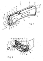
- FIG. 1 shows an embodiment of a stripping tool 1 in a perspective view.
- the stripping tool 1 consists of two half-shells 2 and 3, which are pivotally connected at their longitudinal sides in a known manner with joints 5 about a pivot axis 4.
- the position of the stripping tool 1 shown in FIG. 1 is the non-use position, which is locked by a known blocking element 15.
- the two half shells 2, 3 each have a handle nose 20, 20 '. These gripping noses are arranged in the frontal region of the half-shells 2, 3. They go into the end faces 6, 6 'of the half-shells 2, 3 over.
- end faces 6, 6 'of the half-shells 2, 3 and in the extension of the end faces 6, 6' in the region of the handle lugs 20, 20 'knife sets 12, 12', 13, 13 ', 14, 14' are arranged. These lie in a known manner transversely to the longitudinal direction of the two half-shells 2, 3, or to a longitudinal axis 19 of the stripping tool first
- gripping lugs 20, 20 'grip grips 9 which have nubs 10 or the like, which are advantageous for better handling.
- the half shells 2, 3 are also widened in the region of their rear sides 7, 7 ', wherein the widening extends transversely to the longitudinal axis of the stripping tool 1.
- the backs 7, 7 ' are each provided with a recess 16 which advantageously allows the cable to be stripped off to be passed through these recesses 16 at high stripping lengths (see FIG. 3).
- spacers have on the side opposite to the pivot axis 4, in each case an opening 8, which advantageously serves to secure the stripping tool 1, for example, to a chain or the like.
- half-shells 2, 3 each outside on their longitudinal sides on a labeling field 11, which may be provided in a known manner with labels.
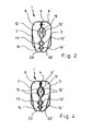
- FIG. 2 shows a view of the stripping tool 1 from the direction indicated by X in FIG. 1.
- blade sets 12, 12 ', 13, 13', 14, 14 'with straight cutting edges are arranged in the opposite inner sides of the end faces 6, 6 introduced in a known manner and fixed in a known manner.
- the blades of the blade sets 12, 12 ', 13, 13', 14, 14 ' are in this illustrated non-use position of the stripping tool 1 parallel opposite.
- the knife set 12, 12 ' which is arranged about the longitudinal axis 19, serves for stripping the outer jacket of a cable.
- the individual wires of this cable can each be stripped with a further set of blades 13, 13 'or 14, 14'.
- the two sets of blades 13, 13 'and 14, 14' are advantageously designed for two different individual wire sizes. Also can with the Knife set 12, 12 'not only a single cable diameter, but a larger number of different cable diameters are processed within a certain range. This results in an advantageously versatile stripping tool. 1
- the stripping tool 1 is shown lying in its open position in one hand. This is the use of the stripping tool 1 by a right-handed person.
- the knife sets 13, 13', 14, 14 'transverse to the longitudinal axis of the respective half-shell 2, 3 and thus also transversely to the grooves 21 are mounted extending.
- the grooves preferably have a semicircular cross section, which is formed corresponding to the respective individual core to be stripped.
- receptacles 18, 18 'for a stop element 17 are introduced into the gripping lugs 20, 20'.
- the stop member 17 can be inserted or inserted into the receptacles 18 or 18 '.
- the receptacles 18, 18 'and the stop element 17 have mutually corresponding latching and guiding means, which consist for example of webs attached to the stop element 17 and corresponding guide grooves in the receptacles 18, 18'.
- the distance of the stop element 17 to the blade sets 13, 13 'and 14, 14' is designed so that the usual stripping length is maintained for individual wires of cables.
- the stop element 17 can be inserted either into the half-shell 2 or into the half-shell 3 into the respective receptacle 18, 18 '. This makes it possible that the stripping tool 1 is suitable for both right-handed and left-handed people.
- FIG. 3 shows the handling for right-handed persons, wherein the stopper member 17 is inserted into the receptacle 18 of the first half-shell 2, which is shown by the dotted line.
- the single core to be stripped can be inserted directly into the first half-shell 2, which is located below, on the stop element 17 in the matching channel 21.
- the knife set 12, 12 ' is also introduced in a known manner near the pivot axis 4 in the end faces 6, 6' of the two half-shells 2, 3.
- the gripping lugs 20, 20 ' are arranged close to the installation location of the blade sets 12, 12', 13, 13 ', 14, 14', an optimal force acting on the blade set 12, 12 'is advantageously achieved by the lever action of the gripping lugs 20, 20 'allows what is required for the stripping of the outer jacket of the cable.
- the design of the stripping tool 1 with its two half shells 2, 3 is advantageously designed so that the hand of the user during the removal of the previously separated by the knife insulation particular hold by the broadening of the half shells 2, 3 to the backs 7, 7 'out ,
- the handling of the stripping tool 1 is generally known and will not be explained in detail here.
- the half-shells 2, 3 are trough-shaped in their cross-section and reinforced by known injection-molding measures, for example by ribs.
- the trough-shaped cross section with its wide surface offers an advantageous introduction of force from the hand into the stripping tool 1.
- the material of the half-shells 2, 3 is preferably plastic with a glass fiber reinforcement, which thereby obtains advantageous properties such as impact resistance and durability.
- the blade sets 12, 12 ', 13, 13', 14, 14 ' can each be embodied integrally on one side of the end faces 6, 6' of the half-shells 2, 3 as well as in several pieces.
- the blade sets 13, 13 'and 14, 14' each formed on one side in one piece, wherein the blade set 12, 12 'is formed individually.
- the blade set 12, 12 ' is two-piece on one side, with the individual blade parts not being disposed in a longitudinal direction in which the other blade sets 13, 13' and 14, 14 'lie, but at an angle to this longitudinal direction stand. This is particularly advantageous, since hereby the cutting process takes place in the outer shell of the insulation of the cable in two places and thus facilitates this process.
- the stripping tool 1 is provided with only one set of blades 13, 13 'for the inner cable cores. It is also conceivable that the stripping tool 1 also with more than two sets of blades 13, 13 'and 14, 14' as the illustrated embodiment shows, can be provided for the inner wires of the cable.
- FIG. 4 shows the view of the stripping tool 1 on its end faces 6, 6 'from the X-direction according to FIG. 1 and according to FIG. 2, variants of knife sets 12, 12', 13, 13 ', 14, 14' being used.
- the blade sets 13, 13 ', 14, 14' are individually or both with provided a groove, which makes the stripping of the individual wires particularly simple.
Landscapes
- Removal Of Insulation Or Armoring From Wires Or Cables (AREA)
Claims (14)
- Outil de dénudage pour enlever des isolations extérieures et/ou des isolations de conducteurs de câbles électriques à un ou plusieurs conducteurs, composé de demi-coques (2, 3) susceptibles de pivoter, reliées au niveau de leurs côtés longitudinaux, avec des ergots de saisie (20) et avec des jeux de lames (12, 12', 13, 13', 14, 14') transversalement par rapport à la direction longitudinale des demi-coques (2, 3), caractérisé en ce que les ergots de saisie (20) sont disposés sur des faces frontales (6) communes des demi-coques (2, 3) et présentent au moins un jeu de lames (13, 13', 14, 14') pour l'enlèvement de l'isolation de conducteur, sachant que le jeu de lames (12, 12') prévu pour l'enlèvement de l'isolation extérieure est disposé dans les faces frontales (6) des demi-coques (2, 3), entre les lames (13, 13', 14, 14') et un axe de pivotement (4) des demi-coques (2, 3).
- Outil de dénudage selon la revendication 1, caractérisé en ce qu'aux jeux de lames (13, 13', 14, 14') prévus dans les ergots de saisie (20) est associé un élément de butée (17) placé à un espacement déterminé.
- Outil de dénudage selon la revendication 2, caractérisé en ce que l'élément de butée (17) est réalisé de façon à pouvoir être enfiché dans des logements (18) correspondants des ergots de saisie (20).
- Outil de dénudage selon la revendication 3, caractérisé en ce que les logements (18) et l'élément de butée (17) présentent des moyens d'encliquetage et de guidage.
- Outil de dénudage selon l'une des revendications 2 à 4, caractérisé en ce que l'élément de butée (17) présente une surface de butée, disposée transversalement par rapport l'axe longitudinal (19).
- Outil de dénudage selon l'une des revendications 1 à 5, caractérisé en ce que les ergots de saisie (20) présentent des auges de saisie (9) extérieures et, intérieurement derrière les jeux de lames (13, 13', 14, 14'), parallèlement à l'axe longitudinal (19) des demi-coques (2, 3), présentent au moins une goulotte (21) disposée, avec une section transversale en forme de demi-cercle.
- Outil de dénudage selon la revendication 6, caractérisé en ce que les auges de saisie (9) sont munies de tétons (10).
- Outil de dénudage selon l'une des revendications 1 à 7, caractérisé en ce que les demi-coques (2, 3) présentent des faces arrière (7, 7') élargies transversalement par rapport à leur direction longitudinale.
- Outil de dénudage selon la revendication 8, caractérisé en ce que les faces arrière (7, 7') élargies des demi-coques (2, 3) présentent des évidements (16).
- Outil de dénudage selon l'une des revendications 1 à 9, caractérisé en ce que les demi-coques (2, 3) présentent une section transversale en forme d'auge.
- Outil de dénudage selon l'une des revendications 1 à 10, caractérisé en ce que les demi-coques (2, 3) sont formées à partir d'un matériau synthétique résistant aux chocs.
- Outil de dénudage selon l'une des revendications 1 à 11, caractérisé en ce que les lames opposées du jeu de lames (12, 12') sont réalisées chacune d'une seule pièce, ou chacune en plusieurs pièces,
- Outil de dénudage selon la revendication 12, caractérisé en ce que les lames du jeu de lames (12, 12') réalisées en plusieurs pièces, chaque fois inclinées les unes par rapport aux autres de la valeur d'un angle.
- Outil de dénudage selon l'une des revendications 1 à 13, caractérisé en ce que les lames des jeux de lames (13, 13', 14, 14') sont réalisées chacune d'une seule pièce, ou bien chacune en plusieurs pièces.
Priority Applications (3)
| Application Number | Priority Date | Filing Date | Title |
|---|---|---|---|
| DE50303961T DE50303961D1 (de) | 2003-08-14 | 2003-08-14 | Abisolierwerkzeug Uniplus |
| EP20030018433 EP1507324B1 (fr) | 2003-08-14 | 2003-08-14 | Dispositif de dénudage Uniplus |
| PCT/EP2004/006490 WO2005025023A1 (fr) | 2003-08-14 | 2004-06-16 | Outil a denuder uniplus |
Applications Claiming Priority (1)
| Application Number | Priority Date | Filing Date | Title |
|---|---|---|---|
| EP20030018433 EP1507324B1 (fr) | 2003-08-14 | 2003-08-14 | Dispositif de dénudage Uniplus |
Publications (2)
| Publication Number | Publication Date |
|---|---|
| EP1507324A1 EP1507324A1 (fr) | 2005-02-16 |
| EP1507324B1 true EP1507324B1 (fr) | 2006-06-21 |
Family
ID=33560799
Family Applications (1)
| Application Number | Title | Priority Date | Filing Date |
|---|---|---|---|
| EP20030018433 Expired - Lifetime EP1507324B1 (fr) | 2003-08-14 | 2003-08-14 | Dispositif de dénudage Uniplus |
Country Status (3)
| Country | Link |
|---|---|
| EP (1) | EP1507324B1 (fr) |
| DE (1) | DE50303961D1 (fr) |
| WO (1) | WO2005025023A1 (fr) |
Families Citing this family (5)
| Publication number | Priority date | Publication date | Assignee | Title |
|---|---|---|---|---|
| GB2459138A (en) * | 2008-04-12 | 2009-10-14 | David Alexander Duff | Wire preparation device |
| US8151670B2 (en) | 2008-08-01 | 2012-04-10 | Nelson James M | Sheath and conductor strippers |
| GB2472256A (en) * | 2009-07-31 | 2011-02-02 | Philip Ian Evans | A combined surgical laser fibre cleaver and stripper |
| US8677861B2 (en) * | 2011-03-31 | 2014-03-25 | Corning Cable Systems Llc | Bladeless stripping device |
| DE102016101940B4 (de) | 2015-07-17 | 2026-03-19 | Knipex-Werk C. Gustav Putsch Kg | Abisolierwerkzeug |
Family Cites Families (4)
| Publication number | Priority date | Publication date | Assignee | Title |
|---|---|---|---|---|
| US2683308A (en) * | 1951-02-02 | 1954-07-13 | Jr Robert F Cook | Slitter for electric wire conductors |
| DE3310523A1 (de) * | 1983-03-23 | 1984-09-27 | Josef Krampe | Abmantelungswerkzeug |
| DE3222326A1 (de) * | 1982-06-14 | 1983-12-15 | Josef 4715 Ascheberg Krampe | Abmantelungswerkzeug |
| DE29814771U1 (de) * | 1998-08-18 | 1998-11-19 | Krampe, Josef, 59387 Ascheberg | Abmantelungswerkzeug |
-
2003
- 2003-08-14 DE DE50303961T patent/DE50303961D1/de not_active Expired - Lifetime
- 2003-08-14 EP EP20030018433 patent/EP1507324B1/fr not_active Expired - Lifetime
-
2004
- 2004-06-16 WO PCT/EP2004/006490 patent/WO2005025023A1/fr not_active Ceased
Also Published As
| Publication number | Publication date |
|---|---|
| DE50303961D1 (de) | 2006-08-03 |
| WO2005025023A1 (fr) | 2005-03-17 |
| EP1507324A1 (fr) | 2005-02-16 |
Similar Documents
| Publication | Publication Date | Title |
|---|---|---|
| DE69831996T2 (de) | Handwerkzeug | |
| DE2162818B2 (de) | Mehrzweckzange fuer elektriker | |
| DE102005008328A1 (de) | Abisolierzange mit weichem Griff | |
| DE29901705U1 (de) | Mehrzweckwerkzeug | |
| EP3680999B1 (fr) | Outil de dénudage | |
| DE202008008012U1 (de) | Zangengriff | |
| EP3784438A1 (fr) | Pince | |
| CH678906A5 (fr) | ||
| DE69801155T2 (de) | Werkzeug und verfahren zum umhüllen von kabeln | |
| EP1507324B1 (fr) | Dispositif de dénudage Uniplus | |
| DE3030610A1 (de) | Werkzeug zum abisolieren eines isolierten elektrischen leiters | |
| EP0824770B1 (fr) | Dispositif de denudage de fils | |
| EP3723928A1 (fr) | Dispositif de coupe pour couper des tubes ondulés à longueur et guidage des saillies dans un tel dispositif de coupe | |
| EP1816716A2 (fr) | Outil à dénuder | |
| EP4025386A1 (fr) | Insert de sertissage et pince de sertissage | |
| EP0461080A1 (fr) | Pince à dénuder | |
| DE3331979C2 (fr) | ||
| DE202013102163U1 (de) | Abmantelungswerkzeug für Flachkabel und Rundkabel | |
| DE102011015362B4 (de) | Multifunktionswerkzeug | |
| DE10110869C2 (de) | Abisolierzange | |
| DE202024101563U1 (de) | Zange | |
| DE10209181B4 (de) | Verfahren und Zange zum Abisolieren von Leiterenden | |
| DE3345996C1 (de) | Halter zum unverlierbaren Anordnen eines Bohrfutterschlüssels | |
| DE102016103972A1 (de) | Kabelmesser | |
| DE20217147U1 (de) | Kabelschutzhülle und Kabeleinführgerät zum Einführen von Kabeln |
Legal Events
| Date | Code | Title | Description |
|---|---|---|---|
| PUAI | Public reference made under article 153(3) epc to a published international application that has entered the european phase |
Free format text: ORIGINAL CODE: 0009012 |
|
| AK | Designated contracting states |
Kind code of ref document: A1 Designated state(s): AT BE BG CH CY CZ DE DK EE ES FI FR GB GR HU IE IT LI LU MC NL PT RO SE SI SK TR |
|
| AX | Request for extension of the european patent |
Extension state: AL LT LV MK |
|
| 17P | Request for examination filed |
Effective date: 20050610 |
|
| AKX | Designation fees paid |
Designated state(s): CY DE FR GB IT TR |
|
| GRAP | Despatch of communication of intention to grant a patent |
Free format text: ORIGINAL CODE: EPIDOSNIGR1 |
|
| GRAS | Grant fee paid |
Free format text: ORIGINAL CODE: EPIDOSNIGR3 |
|
| GRAA | (expected) grant |
Free format text: ORIGINAL CODE: 0009210 |
|
| AK | Designated contracting states |
Kind code of ref document: B1 Designated state(s): CY DE FR GB IT TR |
|
| REG | Reference to a national code |
Ref country code: GB Ref legal event code: FG4D Free format text: NOT ENGLISH |
|
| REF | Corresponds to: |
Ref document number: 50303961 Country of ref document: DE Date of ref document: 20060803 Kind code of ref document: P |
|
| GBT | Gb: translation of ep patent filed (gb section 77(6)(a)/1977) |
Effective date: 20060808 |
|
| ET | Fr: translation filed | ||
| PLBE | No opposition filed within time limit |
Free format text: ORIGINAL CODE: 0009261 |
|
| STAA | Information on the status of an ep patent application or granted ep patent |
Free format text: STATUS: NO OPPOSITION FILED WITHIN TIME LIMIT |
|
| 26N | No opposition filed |
Effective date: 20070322 |
|
| PG25 | Lapsed in a contracting state [announced via postgrant information from national office to epo] |
Ref country code: TR Free format text: LAPSE BECAUSE OF FAILURE TO SUBMIT A TRANSLATION OF THE DESCRIPTION OR TO PAY THE FEE WITHIN THE PRESCRIBED TIME-LIMIT Effective date: 20060621 |
|
| PG25 | Lapsed in a contracting state [announced via postgrant information from national office to epo] |
Ref country code: CY Free format text: LAPSE BECAUSE OF FAILURE TO SUBMIT A TRANSLATION OF THE DESCRIPTION OR TO PAY THE FEE WITHIN THE PRESCRIBED TIME-LIMIT Effective date: 20060621 |
|
| REG | Reference to a national code |
Ref country code: DE Ref legal event code: R082 Ref document number: 50303961 Country of ref document: DE Representative=s name: APLEY & STRAUBE PARTNERSCHAFT PATENTANWAELTE, DE Ref country code: DE Ref legal event code: R082 Ref document number: 50303961 Country of ref document: DE Ref country code: DE Ref legal event code: R082 Ref document number: 50303961 Country of ref document: DE Representative=s name: BACKHAUS, MARTIN, DIPL.-ING., DE |
|
| REG | Reference to a national code |
Ref country code: DE Ref legal event code: R082 Ref document number: 50303961 Country of ref document: DE Representative=s name: APLEY & STRAUBE PARTNERSCHAFT PATENTANWAELTE, DE Ref country code: DE Ref legal event code: R082 Ref document number: 50303961 Country of ref document: DE |
|
| REG | Reference to a national code |
Ref country code: FR Ref legal event code: PLFP Year of fee payment: 14 |
|
| REG | Reference to a national code |
Ref country code: FR Ref legal event code: PLFP Year of fee payment: 15 |
|
| REG | Reference to a national code |
Ref country code: FR Ref legal event code: PLFP Year of fee payment: 16 |
|
| REG | Reference to a national code |
Ref country code: DE Ref legal event code: R082 Ref document number: 50303961 Country of ref document: DE Representative=s name: APLEY & STRAUBE PARTNERSCHAFT PATENTANWAELTE, DE |
|
| PGFP | Annual fee paid to national office [announced via postgrant information from national office to epo] |
Ref country code: IT Payment date: 20220826 Year of fee payment: 20 Ref country code: GB Payment date: 20220830 Year of fee payment: 20 Ref country code: DE Payment date: 20220829 Year of fee payment: 20 |
|
| PGFP | Annual fee paid to national office [announced via postgrant information from national office to epo] |
Ref country code: FR Payment date: 20220830 Year of fee payment: 20 |
|
| REG | Reference to a national code |
Ref country code: DE Ref legal event code: R071 Ref document number: 50303961 Country of ref document: DE |
|
| REG | Reference to a national code |
Ref country code: GB Ref legal event code: PE20 Expiry date: 20230813 |
|
| PG25 | Lapsed in a contracting state [announced via postgrant information from national office to epo] |
Ref country code: GB Free format text: LAPSE BECAUSE OF EXPIRATION OF PROTECTION Effective date: 20230813 |