EP1507449A2 - Elektronische Baugruppe mit einem Kühlsystem - Google Patents
Elektronische Baugruppe mit einem Kühlsystem Download PDFInfo
- Publication number
- EP1507449A2 EP1507449A2 EP04005438A EP04005438A EP1507449A2 EP 1507449 A2 EP1507449 A2 EP 1507449A2 EP 04005438 A EP04005438 A EP 04005438A EP 04005438 A EP04005438 A EP 04005438A EP 1507449 A2 EP1507449 A2 EP 1507449A2
- Authority
- EP
- European Patent Office
- Prior art keywords
- temperature
- fan
- heat
- pump
- liquid
- Prior art date
- Legal status (The legal status is an assumption and is not a legal conclusion. Google has not performed a legal analysis and makes no representation as to the accuracy of the status listed.)
- Withdrawn
Links
Images



Classifications
-
- H—ELECTRICITY
- H05—ELECTRIC TECHNIQUES NOT OTHERWISE PROVIDED FOR
- H05K—PRINTED CIRCUITS; CASINGS OR CONSTRUCTIONAL DETAILS OF ELECTRIC APPARATUS; MANUFACTURE OF ASSEMBLAGES OF ELECTRICAL COMPONENTS
- H05K7/00—Constructional details common to different types of electric apparatus
- H05K7/20—Modifications to facilitate cooling, ventilating, or heating
- H05K7/20218—Modifications to facilitate cooling, ventilating, or heating using a liquid coolant without phase change in electronic enclosures
- H05K7/20281—Thermal management, e.g. liquid flow control
-
- F—MECHANICAL ENGINEERING; LIGHTING; HEATING; WEAPONS; BLASTING
- F16—ENGINEERING ELEMENTS AND UNITS; GENERAL MEASURES FOR PRODUCING AND MAINTAINING EFFECTIVE FUNCTIONING OF MACHINES OR INSTALLATIONS; THERMAL INSULATION IN GENERAL
- F16L—PIPES; JOINTS OR FITTINGS FOR PIPES; SUPPORTS FOR PIPES, CABLES OR PROTECTIVE TUBING; MEANS FOR THERMAL INSULATION IN GENERAL
- F16L55/00—Devices or appurtenances for use in, or in connection with, pipes or pipe systems
-
- G—PHYSICS
- G06—COMPUTING OR CALCULATING; COUNTING
- G06F—ELECTRIC DIGITAL DATA PROCESSING
- G06F1/00—Details not covered by groups G06F3/00 - G06F13/00 and G06F21/00
- G06F1/16—Constructional details or arrangements
- G06F1/20—Cooling means
- G06F1/206—Cooling means comprising thermal management
Definitions
- the present invention relates to a cooling system for an electronic equipment, the cooling system comprising a liquid-cooling system that cools a heat generating portion with a liquid as a medium, and a forced air-cooling system that uses a fan to discharge heat transported from the heat generating portion to an outside.
- the liquid-cooling system is adopted as a cooling system for desktop type personal computers and high-density servers that have a margin in a housing space and mount thereon a CPU of high calorific power, and a hybrid system enhanced in cooling capacity by the use of a fan to forcedly radiate heat transmitted to a heat radiating portion has been proposed (for example, see Patent Document 1).
- Patent Document 1 JP-A-2002-353668
- the liquid-cooling system has a great advantage in realization of reduced noise by an arrangement free from use of any fan in addition to its large heat transmitting capacity. Since the hybrid cooling system uses a fan, noise in the system is increased. Also, in the case where a fan and a pump for driving of a liquid are not balanced well in capacity, the fan is in some cases unnecessarily operated even when cooling can be achieved by increasing a fluid flow rate with the use of a pump, and such operation of the fan incurs an increase in noise and shortening of life of the fan in some cases.
- the invention mainly adopts the following construction.
- An electronic equipment provided with a liquid-cooling system, in which heat generated in a heat generating portion is transmitted to a heat radiating portion with a liquid as a medium to achieve cooling, and an air-cooling system, in which heat transmitted to the heat radiating portion is forcedly cooled comprises a pump that circulates the liquid between the heat generating portion and the heat radiating portion, and a fan that forcedly discharges heat of the heat radiating portion to an outside, a temperature sensor that detects temperature of the heat generating portion, and storage information that beforehand prescribes the relationship between temperature of the heat generating portion and voltages of the pump and the fan, and a control device determines and controls voltages of the pump and the fan on the basis of temperature detected by the temperature sensor and the storage information.
- the pump and the fan are operated at predetermined voltages when a load on the electronic equipment is small, a cooling capacity is increased by raising a pump voltage without changing a fan voltage when temperature detected by the temperature sensor exceeds a first temperature, and the cooling capacity is further increased by raising a fan voltage when temperature detected by the temperature sensor exceeds a second temperature higher than the first temperature.
- the second temperature is a critical temperature achieved by the cooling capacity with only the pump.
- noise can be restricted to a minimum in an electronic equipment, in which cooling is difficult with only a liquid-cooling system and there is a need of also using a fan in combination.
- control takes account of a change in viscosity of a liquid that circulates in the system, it is possible to make efficient use of the liquid-cooling system at a high level. Also, excessive operations of both the fan and the pump can be suppressed, and there can be produced an effect that parts thereof are lengthened in life.
- FIG. 1 An electronic equipment provided with a cooling system according to an embodiment of the invention will be described below in detail with reference to Figs. 1 to 8.
- the embodiment will be described taking as an example the case where a cooling system is applied to a desktop type personal computer (referred below to as desktop PC).
- Fig. 1 is a block diagram showing a construction of a cooling system, according to the embodiment of the invention, provided with a liquid-cooling system and a fan air-cooling system.
- Fig. 2 is a graph showing a viscosity characteristic of a circulating liquid used in the cooling system according to the embodiment of the invention.
- Fig. 3 is a graph showing the relationship between temperature of a heat generating portion and voltages of a pump and a fan, the relationship being stored in a control device in the embodiment of the invention.
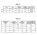
- Fig. 4 is a view showing examples of control values of a fan voltage and a pump voltage at a certain temperature of the heat generating portion in the embodiment.
- Fig. 1 is a block diagram showing a construction of a cooling system, according to the embodiment of the invention, provided with a liquid-cooling system and a fan air-cooling system.
- Fig. 2 is a graph showing a viscosity characteristic of a circulating liquid used in the cooling system according to the embodiment
- Fig. 5 is a view showing the relationship among calorific power, temperature T case of the heat generating portion, liquid temperature T q , and temperature rise ⁇ T due to heat resistance.
- Fig. 6 is a block diagram showing a construction of the control device in the embodiment of the invention.
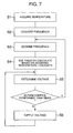
- Fig. 7 is a flowchart illustrating the procedure of control in the control device in the embodiment.
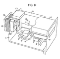
- Fig. 8 is a perspective view showing the case where the cooling system according to the embodiment of the invention is applied to a desktop PC.
- a mother board 7 assembled into a housing 1 mounts thereon a CPU 4, a set 5 of chips, and a memory 6.
- the CPU 4 has a maximum calorific power of 75 W and a specification temperature of 75°C.
- a HDD 8, a FDD 9, and a CD-ROM 10 are mounted as external storage devices.
- the CPU 4 that constitutes a heat generating portion mounts thereto a temperature sensor 21 (see Fig. 1) and transmits temperature information to a control device 12 at constant intervals or continually.
- a heat absorbing jacket 2 formed with a liquid flow passage contacts thermally with the CPU 4, and heat generated in the heat generating portion is absorbed through the heat absorbing jacket 2 by a liquid.
- the liquid is pressurized by the pump 3, circulates through a pipe 14 to radiate heat in a heat sink 15 that constitutes a heat radiating portion, and returns again to the pump 3 via a reserve tank 13.
- the reference numeral 11 denotes an electric power source, and 16 a fan that supplies wind to the heat sink 15.
- the antifreezing solution for prevention of freezing is used for the liquid.
- the antifreezing solution has the viscosity about two times that of water, and a difference in viscosity according to temperature is such that the viscosity at 20°C is about three times that at 60°C.
- Fig. 2 illustrates a difference in cooling capacity according to a difference in viscosity of the antifreezing solution used in the embodiment and an influence of the difference on the system. In Fig.
- the axis of abscissa indicates the viscosity of a liquid (water) that contains the antifreezing solution
- the axis of ordinate indicates temperature T case of the heat generating portion and a volume flow ratio (when water is at 60°C and has the viscosity of 0.48, the volume flow ratio assumes a reference value 1).
- the figure indicates that the higher the liquid viscosity, the smaller the volume flow ratio and the higher the temperature of the heat generating portion. This corresponds to a state, in which the operation is performed at a maximum calorific power (here, 80 W) and both the fan and the pump operate at constant voltages.
- a maximum calorific power here, 80 W
- a temperature sensor 21 is provided to acquire temperature of the main heat generating portion 4 (for example, the CPU in the computer), and temperature acquired by the temperature sensor 21 is transmitted to the control device 12.
- the control device 12 receives temperature information that is transmitted from the temperature sensor 21, at constant intervals or continually, and determines voltages of the pump 3 and the fan 16, as shown in Fig. 3, on the basis of the received temperature and information as beforehand stored.
- points of voltage variation of the fan 16 and the pump 3 that have been beforehand confirmed by means of experiments or the like are stored as a table in the control device 12, and voltages of the fan and the pump are determined with reference to the temperature information as obtained and the table.
- T case T q + ⁇ T
- ⁇ T temperature rise due to heat resistance between the heat absorbing jacket and the liquid
- the liquid temperature T q can be mainly decreased as the heat radiating plate is increased in capacity, that is, the fan is raised in voltage.
- ⁇ T can be decreased by reducing heat resistance of the heat absorbing jacket. In other words, ⁇ T can be decreased by increasing the heat absorbing jacket - the circulating liquid in heat transfer coefficient.
- the volume flow of the circulating liquid is mainly dependent upon the capacity of the pump but is also governed by the viscosity of the circulating liquid and pressure loss in the flow passage. Generally, the higher the temperature, the lower the viscosity of the liquid, and a decrease in volume flow is also restricted. Also, an antifreezing solution having a higher viscosity and a higher temperature dependency than those of water is usually used for the liquid-cooling system for the purpose of prevention of freezing.
- the cooling capacity is enhanced by first keeping the fan at a constant voltage and raising the pump voltage (lowering the heat resistance of the liquid - the heat absorbing jacket), and then raising the fan voltage (see Fig. 3) at a point of time when the cooling capacity is not enhanced even by raising the pump voltage (at a point of time when reduction of ⁇ T due to lowering of heat resistance is small as compared with temperature rise of T q ).
- the calorific power is maximum, the fan and the pump are fully operated.
- the control device is used to control the fan voltage and the pump voltage on the basis of temperature of the heat generating portion and a data table (a graph shown in Fig. 3), in which an optimum fan voltage and an optimum pump voltage have been beforehand confirmed by means of experiments, etc. Also, in the case where a state, in which the control device cannot receive temperature information from the sensor, is brought about when a trouble occurs, both the fan and the pump are fully operated to perform cooling for the sake of safety (the control mode at a point C shown in Fig. 3).
- Both the pump 3 and the fan 16 mounted on a desktop PC that constitutes a configurational example in the embodiment can operate in the voltage range of 7 V to 12 V.
- both the pump 3 and the fan 16 operate at 7 V.
- the control device 12 determines voltages of the pump 3 and the fan 16 on the basis of temperature information transmitted from the temperature sensor 21 and the information shown in Fig. 3.
- a load is small as in a state, in which the device (desktop PC) idles, or the like, both the pump 3 and the fan 16 are caused to operate at 7 V (the point A in Fig. 3).
- cooling is performed by first raising the pump voltage.
- the heat generating portion is at temperature of 5°C. Since the fan voltage is constant at this time, liquid temperature of the system is rising.
- ⁇ T in the heat absorbing jacket increases but heat resistance reduced and ⁇ T is gently rising since the pump is increased in volume flow.
- the limit of cooling is reached due to an increase in pump voltage and the fan 16 is raised in voltage (the point B in Fig. 3) in order to enhance the heat radiating force of the heat radiating plate.
- the heat generating portion is at temperature of 5°C.
- the fan and the pump respectively, operate at 12 V and 9 V to lower temperature of the heat generating portion to the specification temperature or lower.
- T q and ⁇ T are 49°C and 6°C.
- T q and ⁇ T are 51°C and 4°C.
- the pump voltage is low, there is caused reduction in volume flow, and besides, since the fan voltage is high, liquid temperature lowers, the circulating liquid is increased in viscosity, and thereby there is caused further reduction in volume flow.
- the fan voltage is high, liquid temperature lowers, the circulating liquid is increased in viscosity, and thereby there is caused further reduction in volume flow.
- the ratio of T case is high due to liquid temperature but the liquid is correspondingly decreased in viscosity, so that ⁇ T is suppressed to a low level due to an increase in volume flow.
- Noise level assumes 24.2 dB and 22.5 dB, respectively, at the time of (a) and (b) in Fig. 4, and thus noise level is suppressed to be low by 1.7 dB in control at the time of (b) in Fig. 4 even in the case where T case is to be kept at the same temperature.
- control is performed so as not to raise the fan voltage until T case exceeds 5°C.
- T case has exceeded 55°C
- cooling becomes difficult only with a rise in pump voltage that is, in the case where the liquid temperature rises with an increase in calorific power as shown in Fig. 5, the fan voltage is not caused to rise until a stage, at which the heat resistance reducing effect is lowered due to liquid temperature rise, is brought about.
- Fig. 6 is a block diagram of the control device 12. Temperature (S1 in Fig. 7) acquired by the temperature sensor 21 is converted into an oscillating frequency by an oscillation circuit 31 (S2 in Fig. 7).
- the oscillation circuit 31 can oscillate a frequency of 1 kHz to 50 kHz for a temperature range of 20°C to 10°C.
- a frequency counter 32 examines the frequency (S3 in Fig. 7), according to which a PWM control unit 33 oscillates a PWM signal (S4 in Fig. 7). Receiving the signal, a voltage control device 34 operates the fan 15 and the pump 3 (S5 in Fig. 7).
- a voltage control device 34 operates the fan 15 and the pump 3 (S5 in Fig. 7).
- a program of the frequency counter measures the number of times of rise from Low to High in the signal transmitted from the oscillation circuit 31 during 1 msec.
- turnaround time in which rise from Low to High is checked once, is set to 11 ⁇ sec, this checking is repeated 91 times, and the total number of times of rise in 1 msec is counted. Therefore, the sampling frequency is 100 kHz, counting up to a waveform of 50 kHz can be made by the sampling theorem, and measurement up to about 100°C can be made in the oscillation circuit 31.
- the PWM control unit 33 receives a frequency measured by the frequency counter 32, and voltages are determined on the basis of the information to operate the fan 16 and the pump 3. Since the fan 16 and the pump 3 is supplied with electric power while the PWM control is performed, the PWM control stops during the processing of the frequency counter, that is, supplying of electric power to the fan 16 and the pump 3 is stopped, but such stoppage is momentary in 1/1000 sec, so that operation of the fan 16 and the pump 3 will not stop completely. Since the PWM control requires a high-speed processing from the viewpoint of its characteristics, the processing time per once is set to 0.5 msec. Time between change of temperature of the heat generating portion and determination of voltages for the changed temperature is set to 5 sec.
- temperature information of the portion is acquired in order to cool the heat generating portion, and operating voltages of the pump and the fan are determined on the basis of the temperature in view of a difference in cooling capacity due to a difference in viscosity of the liquid, such example is not limitative but the temperature information, the pump, and the fan may be plural.
- voltages may be determined by acquiring temperature information of the respective CPUs, and in some cooling constructions temperature information including other heat generating portions, for example, HDD, electric power source, etc. may be acquired and voltage control may be correspondingly performed.
- the embodiment of the invention has a feature in that in a state, in which a load on an electronic equipment is small, a pump for pressurizing a liquid being a heat transfer medium in a liquid-cooling system and a fan are caused to operate at low speeds, as a load on the electronic equipment increases, only the pump voltage is raised on the basis of temperature information from the temperature sensor 21 mounted on the heat generating portion 4 and temperature information (the table shown in Fig. 3) taking beforehand account of a change in cooling capacity due to the viscosity of the circulating liquid in the system, and the fan voltage is raised in a stage, in which the cooling capacity of the heat generating portion reaches a limit.
Landscapes
- Engineering & Computer Science (AREA)
- Physics & Mathematics (AREA)
- General Engineering & Computer Science (AREA)
- Theoretical Computer Science (AREA)
- Microelectronics & Electronic Packaging (AREA)
- Human Computer Interaction (AREA)
- General Physics & Mathematics (AREA)
- Thermal Sciences (AREA)
- Mechanical Engineering (AREA)
- Cooling Or The Like Of Electrical Apparatus (AREA)
- Cooling Or The Like Of Semiconductors Or Solid State Devices (AREA)
Applications Claiming Priority (2)
| Application Number | Priority Date | Filing Date | Title |
|---|---|---|---|
| JP2003291511 | 2003-08-11 | ||
| JP2003291511A JP2005064186A (ja) | 2003-08-11 | 2003-08-11 | 冷却システムを備えた電子機器 |
Publications (2)
| Publication Number | Publication Date |
|---|---|
| EP1507449A2 true EP1507449A2 (de) | 2005-02-16 |
| EP1507449A3 EP1507449A3 (de) | 2011-11-16 |
Family
ID=33562767
Family Applications (1)
| Application Number | Title | Priority Date | Filing Date |
|---|---|---|---|
| EP04005438A Withdrawn EP1507449A3 (de) | 2003-08-11 | 2004-03-08 | Elektronische Baugruppe mit einem Kühlsystem |
Country Status (6)
| Country | Link |
|---|---|
| US (1) | US7455103B2 (de) |
| EP (1) | EP1507449A3 (de) |
| JP (1) | JP2005064186A (de) |
| KR (1) | KR100610292B1 (de) |
| CN (1) | CN1581366B (de) |
| TW (1) | TWI318557B (de) |
Cited By (2)
| Publication number | Priority date | Publication date | Assignee | Title |
|---|---|---|---|---|
| EP1738679A3 (de) * | 2005-07-01 | 2009-09-16 | Invendo Medical Gmbh | Kühleinrichtung für elektronische Bauteile, vorzugsweise eines Endoskops |
| EP2239646A3 (de) * | 2005-05-06 | 2011-09-28 | Asetek A/S | Verfahren zum Kühlen eines Computersystems |
Families Citing this family (74)
| Publication number | Priority date | Publication date | Assignee | Title |
|---|---|---|---|---|
| US7313815B2 (en) * | 2001-08-30 | 2007-12-25 | Cisco Technology, Inc. | Protecting against spoofed DNS messages |
| TWI300466B (en) | 2002-11-01 | 2008-09-01 | Cooligy Inc | Channeled flat plate fin heat exchange system, device and method |
| US8464781B2 (en) | 2002-11-01 | 2013-06-18 | Cooligy Inc. | Cooling systems incorporating heat exchangers and thermoelectric layers |
| US20050211418A1 (en) * | 2002-11-01 | 2005-09-29 | Cooligy, Inc. | Method and apparatus for efficient vertical fluid delivery for cooling a heat producing device |
| US7836597B2 (en) | 2002-11-01 | 2010-11-23 | Cooligy Inc. | Method of fabricating high surface to volume ratio structures and their integration in microheat exchangers for liquid cooling system |
| US20040233639A1 (en) * | 2003-01-31 | 2004-11-25 | Cooligy, Inc. | Removeable heat spreader support mechanism and method of manufacturing thereof |
| US7591302B1 (en) | 2003-07-23 | 2009-09-22 | Cooligy Inc. | Pump and fan control concepts in a cooling system |
| US7971632B2 (en) | 2003-11-07 | 2011-07-05 | Asetek A/S | Cooling system for a computer system |
| US7616444B2 (en) * | 2004-06-04 | 2009-11-10 | Cooligy Inc. | Gimballed attachment for multiple heat exchangers |
| JP2007148572A (ja) * | 2005-11-24 | 2007-06-14 | Toshiba Corp | 電子機器、温度制御装置および温度制御方法 |
| JP4762699B2 (ja) * | 2005-11-30 | 2011-08-31 | 古河電気工業株式会社 | 電子部品用冷却装置、その温度制御方法及びその温度制御プログラム |
| US20070133170A1 (en) * | 2005-12-08 | 2007-06-14 | Inventec Corporation | Self-protection device of water-cooled dissipation system for computer |
| US8157001B2 (en) | 2006-03-30 | 2012-04-17 | Cooligy Inc. | Integrated liquid to air conduction module |
| US20070227709A1 (en) * | 2006-03-30 | 2007-10-04 | Girish Upadhya | Multi device cooling |
| US7715194B2 (en) | 2006-04-11 | 2010-05-11 | Cooligy Inc. | Methodology of cooling multiple heat sources in a personal computer through the use of multiple fluid-based heat exchanging loops coupled via modular bus-type heat exchangers |
| US20070256815A1 (en) * | 2006-05-04 | 2007-11-08 | Cooligy, Inc. | Scalable liquid cooling system with modular radiators |
| US20080013278A1 (en) * | 2006-06-30 | 2008-01-17 | Fredric Landry | Reservoir for liquid cooling systems used to provide make-up fluid and trap gas bubbles |
| TWM307288U (en) * | 2006-09-01 | 2007-03-01 | Cooler Master Co Ltd | Temperature-controlling equipment of the machine case |
| US7735331B2 (en) * | 2006-09-20 | 2010-06-15 | Ford Global Technologies, Llc | System and method for controlling temperature of an energy storage device in a vehicle |
| US8272428B2 (en) | 2007-07-04 | 2012-09-25 | Denso Corporation | Cooling apparatus using brine |
| US20090225514A1 (en) | 2008-03-10 | 2009-09-10 | Adrian Correa | Device and methodology for the removal of heat from an equipment rack by means of heat exchangers mounted to a door |
| JP5160945B2 (ja) * | 2008-04-21 | 2013-03-13 | 日本モレックス株式会社 | ヒートパイプおよび電子機器 |
| US7791882B2 (en) * | 2008-04-23 | 2010-09-07 | International Business Machines Corporation | Energy efficient apparatus and method for cooling an electronics rack |
| JP4625851B2 (ja) | 2008-04-28 | 2011-02-02 | 株式会社日立製作所 | 冷却システム及びそれを備えた電子機器 |
| US8302419B2 (en) * | 2008-05-02 | 2012-11-06 | Thermal Take Technology Co., Ltd. | Computer cooling apparatus |
| US8782234B2 (en) * | 2008-05-05 | 2014-07-15 | Siemens Industry, Inc. | Arrangement for managing data center operations to increase cooling efficiency |
| US8254422B2 (en) | 2008-08-05 | 2012-08-28 | Cooligy Inc. | Microheat exchanger for laser diode cooling |
| US9238398B2 (en) * | 2008-09-25 | 2016-01-19 | B/E Aerospace, Inc. | Refrigeration systems and methods for connection with a vehicle's liquid cooling system |
| CN101865864B (zh) * | 2010-06-08 | 2012-07-04 | 华东理工大学 | 电子元器件相变冷却效果的测试系统 |
| JP2012007865A (ja) * | 2010-06-28 | 2012-01-12 | Hitachi Plant Technologies Ltd | 冷却システム |
| JP5880998B2 (ja) * | 2010-09-16 | 2016-03-09 | 株式会社リコー | 冷却装置、画像形成装置 |
| CN101977489B (zh) * | 2010-11-09 | 2013-01-30 | 廖维秀 | 用于发热元件的冷却装置及方法 |
| US8947879B2 (en) * | 2010-12-16 | 2015-02-03 | Smartcube, Llc | Portable computer server enclosure |
| KR101169713B1 (ko) | 2010-12-31 | 2012-07-30 | 한국항공우주연구원 | 액적을 이용한 전자 기기의 냉각 장치 |
| WO2014141162A1 (en) | 2013-03-15 | 2014-09-18 | Coolit Systems, Inc. | Sensors, multiplexed communication techniques, and related systems |
| US10365667B2 (en) | 2011-08-11 | 2019-07-30 | Coolit Systems, Inc. | Flow-path controllers and related systems |
| WO2013119243A1 (en) * | 2012-02-09 | 2013-08-15 | Hewlett-Packard Development Company, L.P. | Heat dissipating system |
| JP6061183B2 (ja) * | 2012-02-21 | 2017-01-18 | 株式会社リコー | 冷却装置、及び画像形成装置 |
| EP2901828A4 (de) | 2012-09-28 | 2016-06-01 | Hewlett Packard Development Co | Kühlanordnung |
| CN102914112A (zh) * | 2012-10-26 | 2013-02-06 | 江苏兆胜空调有限公司 | 一种油水冷却装置及其控制方法 |
| WO2014120182A1 (en) | 2013-01-31 | 2014-08-07 | Hewlett-Packard Development Company, L.P. | Liquid cooling |
| US9052252B2 (en) | 2013-03-15 | 2015-06-09 | Coolit Systems, Inc. | Sensors, communication techniques, and related systems |
| US12366870B2 (en) | 2013-03-15 | 2025-07-22 | Coolit Systems, Inc. | Flow-path controllers and related systems |
| JP6096560B2 (ja) * | 2013-03-28 | 2017-03-15 | 株式会社Nttファシリティーズ | 装置冷却システム |
| CN104102310B (zh) * | 2013-04-09 | 2018-01-19 | 北京百度网讯科技有限公司 | 用于服务器整机柜的冷却系统 |
| CN104182013A (zh) * | 2013-05-20 | 2014-12-03 | 深圳先进技术研究院 | 计算机管道网络水冷装置 |
| JP6171826B2 (ja) * | 2013-10-16 | 2017-08-02 | 富士通株式会社 | 電子装置、電子装置の制御方法及び電子装置の制御プログラム |
| CN104717869B (zh) * | 2013-12-13 | 2017-06-23 | 赛恩倍吉科技顾问(深圳)有限公司 | 电子装置及其散热模组 |
| CN103824826B (zh) * | 2014-02-21 | 2017-01-04 | 电子科技大学 | 一种微流道散热方法 |
| TW201542079A (zh) * | 2014-04-24 | 2015-11-01 | Wistron Corp | 針對電子裝置中之電子元件的散熱系統與散熱方法 |
| CN104713394B (zh) * | 2015-03-24 | 2017-03-08 | 华为技术有限公司 | 散热器及热管散热系统 |
| CN205105503U (zh) * | 2015-10-12 | 2016-03-23 | 酷码科技股份有限公司 | 散热模块、散热系统以及电路模块 |
| CN105783046A (zh) * | 2016-03-23 | 2016-07-20 | 浙江绍兴苏泊尔生活电器有限公司 | 家用电器液冷散热系统的控制方法 |
| CN106051815B (zh) * | 2016-05-30 | 2018-02-27 | 大唐贵州发耳发电有限公司 | 一种锅炉火检冷却风系统联锁逻辑 |
| CN106951043B (zh) * | 2017-03-15 | 2023-12-26 | 联想(北京)有限公司 | 电子设备、循环冷却系统 |
| US11452243B2 (en) | 2017-10-12 | 2022-09-20 | Coolit Systems, Inc. | Cooling system, controllers and methods |
| CN109871096A (zh) * | 2017-11-17 | 2019-06-11 | 英业达科技有限公司 | 散热控制方法及其浸入式冷却系统 |
| JP7077067B2 (ja) * | 2018-03-06 | 2022-05-30 | 株式会社Idcフロンティア | 冷却装置、データセンター、及び冷却方法 |
| CN108662823A (zh) * | 2018-03-09 | 2018-10-16 | 桐乡市梧桐春秋机械维修部 | 一种冷却机械 |
| US10325644B1 (en) * | 2018-04-30 | 2019-06-18 | Nanya Technology Corporation | Pump circuit in a DRAM, and method for generating a pump current |
| CN108807313B (zh) * | 2018-07-05 | 2020-06-23 | 安康学院 | 一种微电子器件散热装置 |
| CN109663214A (zh) * | 2018-12-19 | 2019-04-23 | 武汉奇致激光技术股份有限公司 | 一种准分子治疗仪冷却系统结构及其控制方法 |
| US11662037B2 (en) | 2019-01-18 | 2023-05-30 | Coolit Systems, Inc. | Fluid flow control valve for fluid flow systems, and methods |
| CN110045804A (zh) * | 2019-04-15 | 2019-07-23 | 山东超越数控电子股份有限公司 | 一种新型计算机散热机构 |
| US11473860B2 (en) | 2019-04-25 | 2022-10-18 | Coolit Systems, Inc. | Cooling module with leak detector and related systems |
| CN110418549B (zh) | 2019-06-18 | 2021-01-29 | 华为技术有限公司 | 一种散热组件、电子设备 |
| EP4150216A4 (de) | 2020-05-11 | 2023-11-01 | Coolit Systems, Inc. | Flüssigkeitspumpeinheiten sowie zugehörige systeme und verfahren |
| US12041396B2 (en) * | 2020-07-16 | 2024-07-16 | R9 Labs, Llc | Systems and methods for processing data proximate to the point of collection |
| CN113342085B (zh) * | 2021-06-17 | 2022-11-08 | 南昌黑鲨科技有限公司 | 一种识别外置辅助散热设备的方法及系统 |
| JP7108755B1 (ja) * | 2021-07-13 | 2022-07-28 | 浜松ホトニクス株式会社 | 光検出装置及び光検出装置の制御方法 |
| US12200914B2 (en) | 2022-01-24 | 2025-01-14 | Coolit Systems, Inc. | Smart components, systems and methods for transferring heat |
| KR102449125B1 (ko) * | 2022-04-07 | 2022-09-29 | 주식회사 글로벌탑넷 | Gpu 서버 냉각관리 시스템 |
| US12520452B2 (en) | 2022-05-04 | 2026-01-06 | Hoffman Enclosures Inc. | Replaceable pump unit for cooling systems |
| CN118119158B (zh) * | 2024-03-05 | 2024-10-29 | 深圳中菱科技有限公司 | 一种高效能伺服驱动器热管理系统及其方法 |
Family Cites Families (14)
| Publication number | Priority date | Publication date | Assignee | Title |
|---|---|---|---|---|
| US5197858A (en) * | 1991-10-23 | 1993-03-30 | Delta Electronics, Inc. | Thermal control variable speed DC brushless fan |
| GB9613265D0 (en) * | 1996-06-25 | 1996-08-28 | Reddicliffe Edward A | Elecrtonic enclosure |
| TW420326U (en) | 1998-06-04 | 2001-01-21 | Chroma Ate Inc | Rotation speed control circuit for fan |
| TW412629B (en) | 1998-08-18 | 2000-11-21 | Yi Feng Entpr Co Ltd | Central type cooling water system with variable power |
| JP2001056724A (ja) * | 1999-08-18 | 2001-02-27 | Nec Niigata Ltd | パーソナルコンピュータの冷却方式 |
| JP3593287B2 (ja) * | 1999-10-07 | 2004-11-24 | 株式会社ケンウッド | スピーカ駆動装置用強制空冷装置 |
| US6196003B1 (en) * | 1999-11-04 | 2001-03-06 | Pc/Ac, Inc. | Computer enclosure cooling unit |
| US6352055B1 (en) * | 1999-11-24 | 2002-03-05 | Caterpillar Inc. | Engine water pump control system |
| JP2002099356A (ja) * | 2000-09-21 | 2002-04-05 | Toshiba Corp | 電子機器用冷却装置および電子機器 |
| KR100909544B1 (ko) * | 2001-03-02 | 2009-07-27 | 산요덴키가부시키가이샤 | 전자 장치 |
| JP2002257450A (ja) * | 2001-03-02 | 2002-09-11 | Sanyo Electric Co Ltd | 半導体素子の冷却装置 |
| JP2002353668A (ja) | 2001-05-30 | 2002-12-06 | Showa Denko Kk | 電子部品冷却装置および電子部品冷却システム |
| JP2003018861A (ja) * | 2001-06-27 | 2003-01-17 | Nissan Motor Co Ltd | インバータの冷却制御装置 |
| JP2003314936A (ja) * | 2002-04-18 | 2003-11-06 | Matsushita Refrig Co Ltd | 冷却装置 |
-
2003
- 2003-08-11 JP JP2003291511A patent/JP2005064186A/ja active Pending
-
2004
- 2004-03-02 TW TW093105396A patent/TWI318557B/zh not_active IP Right Cessation
- 2004-03-08 EP EP04005438A patent/EP1507449A3/de not_active Withdrawn
- 2004-03-09 KR KR1020040015679A patent/KR100610292B1/ko not_active Expired - Fee Related
- 2004-03-10 US US10/796,049 patent/US7455103B2/en not_active Expired - Lifetime
- 2004-03-10 CN CN200410028256XA patent/CN1581366B/zh not_active Expired - Fee Related
Cited By (2)
| Publication number | Priority date | Publication date | Assignee | Title |
|---|---|---|---|---|
| EP2239646A3 (de) * | 2005-05-06 | 2011-09-28 | Asetek A/S | Verfahren zum Kühlen eines Computersystems |
| EP1738679A3 (de) * | 2005-07-01 | 2009-09-16 | Invendo Medical Gmbh | Kühleinrichtung für elektronische Bauteile, vorzugsweise eines Endoskops |
Also Published As
| Publication number | Publication date |
|---|---|
| EP1507449A3 (de) | 2011-11-16 |
| KR20050018567A (ko) | 2005-02-23 |
| TW200507735A (en) | 2005-02-16 |
| CN1581366B (zh) | 2010-05-26 |
| TWI318557B (en) | 2009-12-11 |
| KR100610292B1 (ko) | 2006-08-09 |
| CN1581366A (zh) | 2005-02-16 |
| US20050034466A1 (en) | 2005-02-17 |
| JP2005064186A (ja) | 2005-03-10 |
| US7455103B2 (en) | 2008-11-25 |
Similar Documents
| Publication | Publication Date | Title |
|---|---|---|
| US7455103B2 (en) | Electronic equipment provided with cooling system | |
| US12150282B2 (en) | Liquid submerged, horizontal computer server rack and systems and method of cooling such a server rack | |
| US7542292B2 (en) | System for efficiently cooling a processor | |
| US8430156B2 (en) | Liquid loop with multiple pump assembly | |
| US7577862B2 (en) | Self adjusting clocks in computer systems that adjust in response to changes in their environment | |
| US8233644B2 (en) | Multiple fan acoustic interaction control | |
| US9310255B2 (en) | Matrix thermal sensing circuit and heat dissipation system | |
| US20050174737A1 (en) | Quiet cooling system for a computer | |
| US20200154604A1 (en) | Apparatus and methods for cooling of an integrated circuit | |
| JP2018181923A (ja) | 冷却システム、冷却装置、及び電子システム | |
| GB2434007A (en) | Controlling the speed of a cooling fan in a computer by generating temperature-load curves and then fan speed-temperature curves | |
| CN112486285A (zh) | 一种计算机智能热管理系统及热管理方法 | |
| EP4025026A2 (de) | Effiziente und robuste systemauslegung und steuerverfahren unter verwendung einer thermoelektrischen kühlung | |
| CN113031672A (zh) | 温度控制方法、系统及存储介质 | |
| US20070053161A1 (en) | Thermal load balancing systems and methods | |
| JP4544527B2 (ja) | 電子機器用液体冷却装置 | |
| CN111966187A (zh) | 一种应用于高密度服务器的外插卡散热管理装置及方法 | |
| US11262110B2 (en) | Heat dissipation module and heat dissipation method thereof | |
| US20030218865A1 (en) | Semiconductor thermal management system | |
| US20040123977A1 (en) | External attachable heat exchanger | |
| JP2002163042A (ja) | 携帯型情報機器 | |
| US20070133170A1 (en) | Self-protection device of water-cooled dissipation system for computer | |
| KR101833236B1 (ko) | 온도 피드백 기능을 구비한 방열 장치 | |
| KR101854153B1 (ko) | 서버컴퓨터 | |
| WO2025256416A1 (zh) | 单相浸没液冷系统、控制方法、控制设备及存储介质 |
Legal Events
| Date | Code | Title | Description |
|---|---|---|---|
| PUAI | Public reference made under article 153(3) epc to a published international application that has entered the european phase |
Free format text: ORIGINAL CODE: 0009012 |
|
| AK | Designated contracting states |
Kind code of ref document: A2 Designated state(s): AT BE BG CH CY CZ DE DK EE ES FI FR GB GR HU IE IT LI LU MC NL PL PT RO SE SI SK TR |
|
| AX | Request for extension of the european patent |
Extension state: AL LT LV MK |
|
| 17P | Request for examination filed |
Effective date: 20060331 |
|
| PUAL | Search report despatched |
Free format text: ORIGINAL CODE: 0009013 |
|
| AK | Designated contracting states |
Kind code of ref document: A3 Designated state(s): AT BE BG CH CY CZ DE DK EE ES FI FR GB GR HU IE IT LI LU MC NL PL PT RO SE SI SK TR |
|
| AX | Request for extension of the european patent |
Extension state: AL LT LV MK |
|
| RIC1 | Information provided on ipc code assigned before grant |
Ipc: G06F 1/20 20060101ALI20111011BHEP Ipc: H05K 7/20 20060101AFI20111011BHEP |
|
| AKX | Designation fees paid |
Designated state(s): DE |
|
| STAA | Information on the status of an ep patent application or granted ep patent |
Free format text: STATUS: THE APPLICATION IS DEEMED TO BE WITHDRAWN |
|
| 18D | Application deemed to be withdrawn |
Effective date: 20120517 |