EP1507629B1 - System mit einer werkzeugaufnahme - Google Patents
System mit einer werkzeugaufnahme Download PDFInfo
- Publication number
- EP1507629B1 EP1507629B1 EP03727169A EP03727169A EP1507629B1 EP 1507629 B1 EP1507629 B1 EP 1507629B1 EP 03727169 A EP03727169 A EP 03727169A EP 03727169 A EP03727169 A EP 03727169A EP 1507629 B1 EP1507629 B1 EP 1507629B1
- Authority
- EP
- European Patent Office
- Prior art keywords
- insertion tool
- tool
- toolholding
- fixture
- insert tool
- Prior art date
- Legal status (The legal status is an assumption and is not a legal conclusion. Google has not performed a legal analysis and makes no representation as to the accuracy of the status listed.)
- Expired - Lifetime
Links
- 230000037431 insertion Effects 0.000 claims description 14
- 238000003780 insertion Methods 0.000 claims description 14
- 239000002184 metal Substances 0.000 description 35
- 210000002105 tongue Anatomy 0.000 description 4
- 230000006378 damage Effects 0.000 description 3
- 238000009434 installation Methods 0.000 description 3
- 230000005540 biological transmission Effects 0.000 description 2
- 230000015572 biosynthetic process Effects 0.000 description 2
- 238000005452 bending Methods 0.000 description 1
- 230000000994 depressogenic effect Effects 0.000 description 1
- 238000005553 drilling Methods 0.000 description 1
- 230000005484 gravity Effects 0.000 description 1
- 239000000463 material Substances 0.000 description 1
Images


Classifications
-
- B—PERFORMING OPERATIONS; TRANSPORTING
- B24—GRINDING; POLISHING
- B24B—MACHINES, DEVICES, OR PROCESSES FOR GRINDING OR POLISHING; DRESSING OR CONDITIONING OF ABRADING SURFACES; FEEDING OF GRINDING, POLISHING, OR LAPPING AGENTS
- B24B23/00—Portable grinding machines, e.g. hand-guided; Accessories therefor
- B24B23/02—Portable grinding machines, e.g. hand-guided; Accessories therefor with rotating grinding tools; Accessories therefor
-
- B—PERFORMING OPERATIONS; TRANSPORTING
- B24—GRINDING; POLISHING
- B24B—MACHINES, DEVICES, OR PROCESSES FOR GRINDING OR POLISHING; DRESSING OR CONDITIONING OF ABRADING SURFACES; FEEDING OF GRINDING, POLISHING, OR LAPPING AGENTS
- B24B45/00—Means for securing grinding wheels on rotary arbors
-
- B—PERFORMING OPERATIONS; TRANSPORTING
- B24—GRINDING; POLISHING
- B24D—TOOLS FOR GRINDING, BUFFING OR SHARPENING
- B24D7/00—Bonded abrasive wheels, or wheels with inserted abrasive blocks, designed for acting otherwise than only by their periphery, e.g. by the front face; Bushings or mountings therefor
- B24D7/16—Bushings; Mountings
Definitions
- the invention is based on a system with a tool holder according to the preamble of claim 1, (see, for example WO-A-01 960 067 ).
- a system with a grinder tool holder for a hand-held angle grinder and a grinding wheel is known.
- the angle grinder has a drive shaft which has a thread on the tool side.
- the grinding machine tool holder has a driver and a clamping nut. To mount the grinding wheel of the driver is pushed with a mounting hole on a collar of the drive shaft and clamped over the clamping nut frictionally against a bearing surface of the drive shaft.
- the driver has a tool side in the axial direction extending collar radially on two opposite Has sides on its outer circumference recesses which extend in the axial direction to a bottom of the collar. Starting from the recesses extending against the drive direction of the drive shaft in each case a groove on the outer circumference of the collar. The grooves are closed against the drive direction of the drive shaft and taper axially from the recesses against the drive direction of the drive shaft.
- the grinding wheel has a hub with a mounting opening in which two opposite, radially inwardly pointing tongues are arranged.
- the tongues can be introduced into the recesses in the axial direction and then into the grooves in the circumferential direction, counter to the drive direction.
- the grinding wheel is positively connected via the tongues in the grooves in the axial direction and frictionally fixed by the tapered contour of the grooves. During operation, the adhesion increases due to acting on the grinding wheel reaction forces acting counter to the drive direction.
- a stopper is arranged in the region of a recess on the circumference of the collar and is movably mounted in an opening in the axial direction. In a working position pointing downwards with the grinding wheel, the stopper is deflected by gravity axially in the direction of the grinding wheel, closes the groove in the direction of the recess and blocks movement of the tongue located in the groove in the drive direction of the drive shaft.
- the invention relates to a system having the features of claim 1.
- the invention relates to a system with a tool holder, which has a driving device, via which an insert tool with a drive shaft is operatively connected, and with an insert tool which is operatively connected via at least one movable against a spring element latching element with the driving device, the engages in an operating position of the insert tool and the insert tool fixed in a form-fitting manner.
- the tool holder and the insert tool have at least two matched, corresponding form elements for simplifying a mounting of the insert tool. It is an advantageous and easy installation of the insert tool achievable, and in particular by the form elements form a guide, so that clamping hooks of the driving device can automatically engage in corresponding recesses of the hub.
- the corresponding form elements are matched with respect to the dimensioning of the insert tool, whereby in particular a correct assignment of a diameter of the insert tool to a rotational speed of the power tool can be ensured and damage can be avoided.
- a correct assignment of a diameter of the insert tool to a rotational speed of the power tool can be ensured and damage can be avoided.
- other dimensions than encoding criterion are conceivable, in particular a strength of the insert tool.
- the mold element arranged on the tool holder is formed by a projection arranged on a collar of the tool holder, extending in the radial direction, and the mold element arranged on the mold element is formed by a recess.
- a radially inwardly extending projection and the tool holder a recess is formed on the hub or on the insert tool.
- the projection in the axial direction has a distance from a contact surface.
- the insert tool can be rotated to reach a locking position under the projection become.
- the projection represents an additional safeguard of the insert tool and provides an additional contribution to safety for the operator.
- At least three uniformly distributed over the circumference projections are arranged on the tool holder.
- the three projections span an unambiguous certain level and form with their end faces an advantageous contact surface for the insert tool.
- the Einsatstechnikzeug can simply be placed on the bearing surface and rotated during assembly in the tool holder until the mold elements are in a mutually corresponding position.
- the finding and threading of the retaining hooks in the corresponding recesses in the hub is thereby significantly facilitated and jamming and tilting of the insertion tool during assembly can be advantageously avoided.
- the projection may be integrally formed on a separate component or advantageously designed in one piece with the tool holder, in the latter case additional components, assembly costs and costs can be saved.
- a cylindrical part of the collar projects in the axial direction over end faces of the form elements.
- the insert tool can be structurally simply centered and rotated during assembly in the tool holder.
- Fig. 1 shows an angle grinder 32 from above with a mounted in a housing 34, not shown electric motor.
- the angle grinder 32 can be guided via a first, in the housing 34 on a side facing away from an insert tool 14, extending in the longitudinal direction handle 36 and a second attached to a transmission housing 38 in the field of insert tool 14, transversely to the longitudinal direction extending handle 40.
- a drive shaft 16 can be driven, at whose end facing the insertion tool 14 a tool holder with a driving device 12 is arranged ( Fig. 2 ).
- the tool holder and the insert tool 14 form a system.
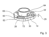
- the tool holder has a driving flange 10, which forms a contact surface 30 for the insertion tool 14 ( Fig. 2 and Fig. 3 ).
- a collar 26 is integrally formed on a side facing the insert tool 14, over which the insert tool 14 is radially centered with its center hole 46 in the mounted state.
- three mold elements 22 are arranged, which are formed by radially outwardly extending projections.
- the integrally formed with the collar 26 form elements 22 are distributed uniformly over an outer circumference of the collar 26 and have in the axial direction 54, 64 a distance 28 to the contact surface 30. With its end facing the insert tool 14, the collar 26 projects beyond the shaped elements 22 in the axial direction 54.
- a metal plate 48 On a side facing away from the insert tool 14 of the driving flange 10 is a metal plate 48 with three circumferentially 50, 52 evenly distributed, integrally formed, extending in the axial direction 54 clamping hooks 56 for axially fixing the insert tool 14 is arranged.
- the clamping hooks 56 are formed in a bending operation on the metal plate 48.
- the driving flange 10 When mounting the driving device 12, the driving flange 10, a spring element 58 and the metal plate 48 is pre-assembled.
- the spring element 58 is not closer to one shown collar of the driving flange 10 is pushed, which points in the direction away from the insert tool 14 direction.
- the clamping hooks 56 of the sheet metal plate 48 which at its free end have a hook-shaped extension with an obliquely pointing in the circumferential direction 52 94, guided in the axial direction 54 through recesses 60 of the driving flange 10, respectively by common areas 62 of the recesses 60 (FIGS. Fig. 2 and 3 ).
- the spring element 58 By compressing and twisting the metal plate 48 and the driving flange 10 against each other, the spring element 58 is biased and the metal plate 48 and the driving flange 10 are positively connected in the axial direction 54, 64, namely by the hook-shaped projections in narrow portions 66 of the recesses 60 are rotated ( Fig. 2 and 3 ).
- the metal plate 48 is then, loaded by the spring element 58, supported on the contact surface 30 of the driving flange 10 via edges of the hook-shaped extensions which point axially in the direction away from the insert tool 14 direction.
- the spring element 58 and the driving flange 10 are pre-assembled, is formed by a coil spring spring member 18 and a drive plate 96 with three evenly distributed over the circumference, extending in the axial direction 54 bolt 20 on a Drive shaft 16 attached ( Fig. 2 ).
- the preassembled module consisting of the metal plate 48, the spring element 58 and the driving flange 10, is mounted on the drive shaft 16.
- the bolts 20 are in the assembly by the periphery of the metal plate 48th formed tabs 68, the holes 70, and guided by located in the driving flange 10 through holes 72 and engage in the assembled state through the through holes 72 therethrough.
- the metal plate 48 and the drive plate 96 are secured to each other via the bolts 20 against rotation.
- the tool holder is secured on the drive shaft 16 with a screw 74.
- the insertion tool 14 formed by a cutting disk has a sheet metal hub 42 formed by a separate component, which has three uniformly distributed, in the circumferential direction 50, 52, in the axial direction 54, cup-shaped recesses 76 whose diameter is slightly larger than the diameter of the bolt 20. Furthermore, the sheet metal hub 42 has three evenly distributed in the circumferential direction 50, 52, extending in the circumferential direction 50, 52 recesses 78, each having a narrow and a wide range 80, 82.
- the diameter of the center hole 46 of the sheet metal hub 42 is selected so that the insert tool 14 can be clamped with a conventional clamping system with a clamping flange and a spindle nut on a conventional angle grinder. It ensures a so-called backward compatibility.
- the sheet metal hub 42 of the insertion tool 14 has three mold elements 24 which are distributed in the circumferential direction 50, 52 uniformly over the circumference of the centering bore 46 ( Fig.2 ).
- the mold elements 24 are formed here by recesses.
- the mold elements 22 of the tool holder and the mold elements 24 of the insert tool 14 are matched, corresponding mold elements to simplify installation of the insert tool 14. Furthermore, the corresponding form elements 22, 24 form a coding means for avoiding assembly of an impermissible insert tool of the same kind Form elements 22, 24 coordinated with respect to a diameter of the insert tool 14, so that use tools for use in high speed machines have a wide shape element or a wide coding and insert tools for use in machines with low speed a narrow form element or a narrow encoding.
- the sheet metal hub 42 of the insert tool 14 is connected via a rivet connection firmly with an abrasive and pressed and is executed by a pointing in the axial direction 64 formation 44 cup-shaped.
- the insert tool 14 When mounting the insert tool 14, the insert tool 14 is pushed with its center hole 46 on the mold elements 22 in the axial direction 54 superior part of the collar 26 and pre-centered radially. The insert tool 14 comes here to contact surfaces 84 of the mold elements 22 to lie. Twisting the insert tool 14 in the circumferential direction 50, 52 brings the mold elements 22, 24 to cover. The insert tool 14 or the sheet metal hub 42 can then slide in the axial direction 64 in the direction of the contact surface 30, and the sheet metal hub 42 comes to rest on the bolt 20.
- a subsequent pressing of the sheet metal hub 42 to the contact surface 30 of the driving flange 10 causes the bolt 20 in the Through holes 72 and the drive plate 96 are axially displaced against the spring force of the spring element 18 on the drive shaft 16 in the direction away from the insert tool 14 64 direction.
- radially outwardly directed recesses 86 of the driver disk 96 engage in corresponding locking pockets 88 of a bearing flange 90 fixedly connected to the transmission housing 38 and lock the drive shaft 16.
- the sheet metal hub 42 can be rotated counter to a drive direction 98.
- the rotation of the sheet metal hub 42 causes the sheet metal hub 42 to slide with its edge of the centering bore 46 into the distance 28 between the mold elements 22 and the abutment surface 30 of the driving flange 10 and can be secured against falling down by the shaped elements 22 in the axial direction.
- the rotation of the sheet metal hub 42 causes the hook-shaped projections to be displaced into the arcuate, narrow regions 80 of the recesses 78 of the sheet metal hub 42.
- the metal plate 48 is moved with the clamping hooks 56 by not shown inclined surfaces axially against the pressure of the spring element 58 in the direction 54 until the contact surfaces of the hook-shaped projections in the arcuate, narrow areas 80 laterally come to rest next to the recesses 78 of the sheet metal hub 42.
- a release button 92 is pressed in the axial direction 64.
- the release button 92 pushes the drive plate 96 in the axial direction 64, and the recesses 86 of the drive plate 96 engage with the locking pockets 88 in engagement.
- the drive shaft 16 is locked.
- the bolts 20 are in this case with the recesses 76 of the sheet metal hub 42 disengaged, and the sheet metal hub 42 can be rotated in the circumferential direction 52 until the clamping hooks 56 can slide through the recesses 78.
- the mold elements 22, 24 in this case reach into a corresponding position, and the sheet metal hub 42 can be removed in the axial direction 54.
Landscapes
- Engineering & Computer Science (AREA)
- Mechanical Engineering (AREA)
- Finish Polishing, Edge Sharpening, And Grinding By Specific Grinding Devices (AREA)
- Constituent Portions Of Griding Lathes, Driving, Sensing And Control (AREA)
- Polishing Bodies And Polishing Tools (AREA)
Description
- Die Erfindung geht aus von einem System mit einer Werkzeugaufnahme nach dem Oberbegriff des Anspruchs 1, (siehe z.B.
WO-A-01 960 067 - Aus der
EP 0 904 896 A2 ist ein System mit einer Schleifmaschinenwerkzeugaufnahme für eine handgeführte Winkelschleifmaschine und einer Schleifscheibe bekannt. Die Winkelschleifmaschine besitzt eine Antriebswelle, die werkzeugseitig ein Gewinde aufweist. - Die Schleifmaschinenwerkzeugaufnahme besitzt einen Mitnehmer und eine Spannmutter. Zur Montage der Schleifscheibe wird der Mitnehmer mit einer Montageöffnung auf einen Bund der Antriebswelle aufgeschoben und über die Spannmutter kraftschlüssig gegen eine Auflagefläche der Antriebswelle verspannt. Der Mitnehmer besitzt einen sich werkzeugseitig in axialer Richtung erstreckenden Bund, der radial an zwei gegenüberliegenden Seiten an seinem Außenumfang Ausnehmungen aufweist, die sich in axialer Richtung bis zu einem Grund des Bunds erstrecken. Ausgehend von den Ausnehmungen erstreckt sich entgegen der Antriebsrichtung der Antriebswelle jeweils eine Nut am Außenumfang des Bunds. Die Nuten sind entgegen der Antriebsrichtung der Antriebswelle verschlossen und verjüngen sich axial ausgehend von den Ausnehmungen entgegen der Antriebsrichtung der Antriebswelle.
- Die Schleifscheibe besitzt eine Nabe mit einer Montageöffnung, in der zwei gegenüberliegende, radial nach innen weisende Zungen angeordnet sind. Die Zungen können in axialer Richtung in die Ausnehmungen und anschließend in Umfangsrichtung, entgegen der Antriebsrichtung, in die Nuten eingeführt werden. Die Schleifscheibe ist über die Zungen in den Nuten in axialer Richtung formschlüssig und durch die sich verjüngende Kontur der Nuten kraftschlüssig fixiert. Während des Betriebs nimmt der Kraftschluß infolge von auf die Schleifscheibe wirkenden Reaktionskräften zu, die entgegen der Antriebsrichtung wirken.
- Um ein Ablaufen der Schleifscheibe beim Abbremsen der Antriebswelle vom Mitnehmer zu vermeiden, ist im Bereich einer Ausnehmung am Umfang des Bunds ein Stopper angeordnet, der in einer Öffnung in axialer Richtung beweglich gelagert ist. In einer mit der Schleifscheibe nach unten weisenden Arbeitsstellung wird der Stopper durch die Schwerkraft axial in Richtung Schleifscheibe ausgelenkt, verschließt in Richtung Ausnehmung die Nut und blockiert eine Bewegung der in der Nut befindlichen Zunge in Antriebsrichtung der Antriebswelle.
- Die Erfindung betrifft ein system mit den Merkmalen des Anspruchs 1.
- Die Erfindung geht aus von einem System mit einer Werkzeugaufnahme, die eine Mitnahmevorrichtung aufweist, über die ein Einsatzwerkzeug mit einer Antriebswelle wirkungsmäßig verbindbar ist, und mit einem Einsatzwerkzeug, das über zumindest ein gegen ein Federelement bewegbar gelagertes Rastelement mit der Mitnahmevorrichtung wirkungsmäßig verbindbar ist, das in einer Betriebsstellung des Einsatzwerkzeugs einrastet und das Einsatzwerkzeug formschlüssig fixiert.
- Es wird vorgeschlagen, daß die Werkzeugaufnahme und das Einsatzwerkzeug zumindest zwei aufeinander abgestimmte, korrespondierende Formelemente zur Vereinfachung einer Montage des Einsatzwerkzeugs aufweisen. Es ist eine vorteilhafte und einfache Montage des Einsatzwerkzeugs erreichbar, und zwar insbesondere indem die Formelemente eine Führung bilden, so daß Spannhaken der Mitnahmevorrichtung automatisch in korrespondierende Ausnehmungen der Nabe eingreifen können.
- Vorteilhaft bilden die korrespondierenden Formelemente hinsichtlich zumindest eines Parameters ein Kodierungsmittel zur Vermeidung einer Montage eines unzulässigen Einsatzwerkzeugs derselben Art. Es kann konstruktiv einfach ein Schutz für eine Handwerkzeugmaschine und für das Einsatzwerkzeug gegen eine Beschädigung und/oder Zerstörung durch eine etwaige Fehlbelastung, wie insbesondere durch eine zu hohe Drehzahl, erreicht werden. Eine Kodierung ist anhand verschiedener Parameter denkbar, die der Fachmann als sinnvoll erachtet, wie z.B. eine Dimensionierung des Einsatzwerkzeugs, eine maximal zulässige Drehzahl, ein Einsatzzweck des Einsatzwerkzeugs, ein zu bearbeitendes Material usw. Es sind auch elektronische Kodierungsmittel denkbar, mit denen z.B. eine Drehzahl eines Motors bzw. einer Antriebseinheit in Abhängigkeit vom Einsatzwerkzeug begrenzbar ist oder bei einem Einsatz eines unzulässigen Einsatzwerkzeugs eine Stromzufuhr unterbrochen werden kann.
- Vorteilhaft sind die korrespondierenden Formelemente hinsichtlich der Dimensionierung des Einsatzwerkzeugs aufeinander abgestimmt, wodurch insbesondere eine korrekte Zuordnung eines Durchmessers des Einsatzwerkzeugs zu einer Drehzahl der Handwerkzeugmaschine sichergestellt werden kann und Beschädigungen vermeidbar sind. Neben dem Durchmesser sind jedoch auch andere Dimensionen als Kodierungskriterium denkbar, wie insbesondere eine Stärke des Einsatzwerkzeugs.
- Vorteilhaft ist das an der Werkzeugaufnahme angeordnete Formelement von einem an einem Bund der Werkzeugaufnahme angeordneten, sich in radialer Richtung erstreckenden Vorsprung und das am Einsatzwerkzeug angeordnete Formelement von einer Ausnehmung gebildet. Es sind große Zentrierflächen für eine einfache und sichere Montage des Einsatzwerkzeugs in der Werkzeugaufnahme erreichbar. Denkbar ist jedoch auch, daß an die Nabe bzw. an das Einsatzwerkzeug ein sich radial nach innen erstreckender Vorsprung und an die Werkzeugaufnahme eine Ausnehmung angeformt ist.
- In einer weiteren Ausgestaltung der Erfindung wird vorgeschlagen, daß der Vorsprung in axialer Richtung einen Abstand zu einer Anlagefläche aufweist. Das Einsatzwerkzeug kann zum Erreichen einer Arretierposition unter den Vorsprung gedreht werden. Der Vorsprung stellt dabei eine zusätzliche Sicherung des Einsatzwerkzeug dar und liefert einen zusätzlichen Beitrag zur Sicherheit für den Bediener.
- Ferner wird vorgeschlagen, daß an der Werkzeugaufnahme zumindest drei gleichmäßig über den Umfang verteilte Vorsprünge angeordnet sind. Die drei Vorsprünge spannen eine eindeutige bestimmte Ebene auf und bilden mit ihren Stirnseiten eine vorteilhafte Anlagefläche für das Einsatzwerkzeug. Das Einsatswerkzeug kann bei der Montage in der Werkzeugaufnahme einfach auf die Anlagefläche gelegt und gedreht werden, bis die Formelemente sich in einer zueinander korrespondierenden Position befinden. Das Finden und Einfädeln der Haltehaken in die entsprechenden Ausnehmungen in der Nabe wird dadurch deutlich erleichtert und ein Verklemmen und Verkanten des Einsatzwerkzeugs bei der Montage kann vorteilhaft vermieden werden.
- Der Vorsprung kann an ein separates Bauteil angeformt oder vorteilhaft einstückig mit der Werkzeugaufnahme ausgeführt sein, wobei im letzteren Fall zusätzliche Bauteile, Montageaufwand und Kosten eingespart werden können.
- In einer weiteren Ausgestaltung der Erfindung wird vorgeschlagen, daß ein zylindrischer Teil des Bundes in axialer Richtung über Stirnflächen der Formelemente ragt. Das Einsatzwerkzeug kann bei der Montage in der Werkzeugaufnahme konstruktiv einfach zentriert und gedreht werden.
- Weitere Vorteile ergeben sich aus der folgenden Zeichnungsbeschreibung. In der Zeichnung ist ein Ausführungsbeispiel der Erfindung dargestellt. Die Zeichnung, die Beschreibung und die Ansprüche enthalten zahlreiche Merkmale in Kombination. Der Fachmann wird die Merkmale zweckmäßigerweise auch einzeln betrachten und zu sinnvollen weiteren Kombinationen zusammenfassen.
- Es zeigen:
- Fig. 1
- einen schematisch dargestellten Winkelschlei- fer von oben,
- Fig. 2
- eine Explosionszeichnung eines Systems mit ei- ner Werkzeugaufnahme,
- Fig. 3
- eine vergrößerte Darstellung eines Mitnah- meflansches aus
Fig. 2 . -
Fig. 1 zeigt einen Winkelschleifer 32 von oben mit einem in einem Gehäuse 34 gelagerten, nicht näher dargestellten Elektromotor. Der Winkelschleifer 32 ist über einen ersten, im Gehäuse 34 auf einer einem Einsatzwerkzeug 14 abgewandten Seite integrierten, sich in Längsrichtung erstreckenden Handgriff 36 und über einen zweiten an einem Getriebegehäuse 38 im Bereich des Einsatzwerkzeugs 14 befestigten, sich quer zur Längsrichtung erstreckenden Handgriff 40 führbar. Mit dem Elektromotor ist über ein nicht näher dargestelltes Getriebe eine Antriebswelle 16 antreibbar, an deren zum Einsatzwerkzeug 14 weisenden Ende eine Werkzeugaufnahme mit einer Mitnahmevorrichtung 12 angeordnet ist (Fig. 2 ). Die Werkzeugaufnahme und das Einsatzwerkzeug 14 bilden ein System. - Die Werkzeugaufnahme besitzt einen Mitnahmeflansch 10, der eine Anlagefläche 30 für das Einsatzwerkzeug 14 bildet (
Fig. 2 undFig. 3 ). An dem Mitnahmeflansch 10 ist auf einer dem Einsatzwerkzeug 14 zugewandten Seite ein Bund 26 angeformt, über den das Einsatzwerkzeug 14 mit seiner Zentrierbohrung 46 im montierten Zustand radial zentriert ist. An dem Bund 26 sind drei Formelemente 22 angeordnet, die von sich radial nach außen erstreckenden Vorsprüngen gebildet sind. Die mit dem Bund 26 einstückig ausgeführten Formelemente 22 sind gleichmäßig über einen Außenumfang des Bunds 26 verteilt angeordnet und weisen in axialer Richtung 54, 64 einen Abstand 28 zur Anlagefläche 30 auf. Mit seinem zum Einsatzwerkzeug 14 weisenden Ende überragt der Bund 26 in axialer Richtung 54 die Formelemente 22. - Auf einer des Einsatzwerkzeugs 14 abgewandten Seite des Mitnahmeflansches 10 ist eine Blechplatte 48 mit drei in Umfangsrichtung 50, 52 gleichmäßig verteilten, einstückig angeformten, sich in axialer Richtung 54 erstreckenden Spannhaken 56 zur axialen Fixierung des Einsatzwerkzeugs 14 angeordnet. Die Spannhaken 56 sind in einem Biegevorgang an die Blechplatte 48 angeformt.
- Bei der Montage der Mitnahmevorrichtung 12 wird der Mitnahmeflansch 10, ein Federelement 58 und die Blechplatte 48 vormontiert. Dabei wird das Federelement 58 auf einen nicht näher dargestellten Bund des Mitnahmeflansches 10 aufgeschoben, der in die vom Einsatzwerkzeug 14 abgewandte Richtung weist. Anschließend werden die Spannhaken 56 der Blechplatte 48, die an ihrem freien Ende einen hakenförmigen Fortsatz mit einer in Umfangsrichtung 52 weisenden Schrägfläche 94 aufweisen, in axialer Richtung 54 durch Ausnehmungen 60 des Mitnahmeflansches 10 geführt, und zwar jeweils durch verbreitete Bereiche 62 der Ausnehmungen 60 (
Fig. 2 und3 ). Durch Zusammendrücken und Verdrehen der Blechplatte 48 und des Mitnahmeflansches 10 gegeneinander wird das Federelement 58 vorgespannt und die Blechplatte 48 und der Mitnahmeflansch 10 werden in axialer Richtung 54, 64 formschlüssig verbunden, und zwar indem die hakenförmigen Fortsätze in schmale Bereiche 66 der Ausnehmungen 60 verdreht werden (Fig. 2 und3 ). Die Blechplatte 48 ist anschließend, belastet durch das Federelement 58, an der Anlagefläche 30 des Mitnahmeflansches 10 über Kanten der hakenförmigen Fortsätze abgestützt, die axial in die vom Einsatzwerkzeug 14 abgewandte Richtung weisen. - Nachdem die Blechplatte 48 mit den angeformten Spannhaken 56, das Federelement 58 und der Mitnahmeflansch 10 vormontiert sind, wird ein von einer Schraubenfeder gebildetes Federelement 18 und eine Mitnehmerscheibe 96 mit drei gleichmäßig über den Umfang verteilten, sich in axialer Richtung 54 erstreckenden Bolzen 20 auf eine Antriebswelle 16 aufgesteckt (
Fig. 2 ). - Anschließend wird die vormontierte Baugruppe, bestehend aus der Blechplatte 48, dem Federelement 58 und dem Mitnahmeflansch 10, auf die Antriebswelle 16 montiert. Die Bolzen 20 werden bei der Montage durch am Umfang der Blechplatte 48 angeformte Laschen 68, die Bohrungen 70 aufweisen, und durch im Mitnahmeflansch 10 befindliche Durchgangsbohrungen 72 geführt und greifen im montierten Zustand durch die Durchgangsbohrungen 72 hindurch. Die Blechplatte 48 und die Mitnehmerscheibe 96 sind über die Bolzen 20 gegen Verdrehen zueinander gesichert.
- Die Werkzeugaufnahme wird auf der Antriebswelle 16 mit einer Schraube 74 gesichert. Das von einer Trennscheibe gebildete Einsatzwerkzeug 14 besitzt eine von einem separaten Bauteil gebildete Blechnabe 42, die in Umfangsrichtung 50, 52 hintereinander drei gleichmäßig verteilte, sich in axialer Richtung 54 erstreckende, napfförmige Ausnehmungen 76 aufweist, deren Durchmesser geringfügig größer ist als der Durchmesser der Bolzen 20. Ferner besitzt die Blechnabe 42 drei gleichmäßig in Umfangsrichtung 50, 52 verteilte, sich in Umfangsrichtung 50, 52 erstreckende Ausnehmungen 78, die jeweils einen schmalen und einen breiten Bereich 80, 82 aufweisen.
- Der Durchmesser der Zentrierbohrung 46 der Blechnabe 42 ist so gewählt, daß das Einsatzwerkzeug 14 auch mit einem herkömmlichen Spannsystem mit einem Spannflansch und einer Spindelmutter auf eine herkömmliche Winkelschleifmaschine aufgespannt werden kann. Es wird eine sogenannte Abwärtskompatibilität sichergestellt.
- Die Blechnabe 42 des Einsatzwerkzeugs 14 weist drei Formelemente 24 auf, die in Umfangsrichtung 50, 52 gleichmäßig über den Umfang der Zentrierbohrung 46 verteilt sind (
Fig.2 ). Die Formelemente 24 sind hierbei von Ausnehmungen gebildet. - Die Formelemente 22 der Werkzeugaufnahme und die Formelemente 24 des Einsatzwerkzeugs 14 sind aufeinander abgestimmte, korrespondierende Formelemente zur Vereinfachung einer Montage des Einsatzwerkzeugs 14. Ferner bilden die korrespondierenden Formelemente 22, 24 ein Kodierungsmittel zur Vermeidung einer Montage eines unzulässigen Einsatzwerkzeugs derselben Art. Hierfür sind die korrespondierenden Formelemente 22, 24 hinsichtlich eines Durchmessers des Einsatzwerkzeugs 14 aufeinander abgestimmt, so daß Einsatzwerkzeuge für den Einsatz in Maschinen mit hoher Drehzahl ein breites Formelement bzw. eine breite Kodierung aufweisen und Einsatzwerkzeuge für den Einsatz in Maschinen mit niederer Drehzahl ein schmales Formelement bzw. eine schmale Kodierung.
- Die Blechnabe 42 des Einsatzwerkzeugs 14 ist über eine Nietverbindung fest mit einem Schleifmittel verbunden und verpreßt und ist durch eine in axialer Richtung 64 weisende Ausformung 44 napfförmig ausgeführt.
- Bei einer Montage des Einsatzwerkzeug 14 wird das Einsatzwerkzeug 14 mit seiner Zentrierbohrung 46 auf den die Formelemente 22 in axialer Richtung 54 überragenden Teil des Bunds 26 aufgeschoben und radial vorzentriert. Das Einsatzwerkzeug 14 kommt hierbei auf Anlageflächen 84 der Formelemente 22 zum Liegen. Ein Verdrehen des Einsatzwerkzeugs 14 in Umfangsrichtung 50, 52 bringt die Formelemente 22, 24 zur Deckung. Das Einsatzwerkzeug 14 bzw. die Blechnabe 42 kann anschließend in axialer Richtung 64 in Richtung der Anlagefläche 30 gleiten, und die Blechnabe 42 kommt auf den Bolzen 20 zum Liegen. Ein anschließendes Andrücken der Blechnabe 42 an die Anlagefläche 30 des Mitnahmeflansches 10 bewirkt, daß die Bolzen 20 in den Durchgangsbohrungen 72 und die Mitnehmerscheibe 96 gegen eine Federkraft des Federelements 18 auf der Antriebswelle 16 axial in die vom Einsatzwerkzeug 14 abgewandte Richtung 64 verschoben werden. Hierbei greifen radial nach außen gerichtete Ausnehmungen 86 der Mitnehmerscheibe 96 in entsprechende Arretiertaschen 88 eines fest mit dem Getriebegehäuse 38 verbundenen Lagerflansches 90 und arretieren die Antriebswelle 16.
- Beim Niederdrücken der Blechnabe 42 auf die Anlagefläche 30 finden die Spannhaken 56 automatisch in die breiten Bereiche 82 der Ausnehmungen 78 in der Blechnabe 42.
- Sind die hakenförmigen Fortsätze der Spannhaken 56 durch die breiten Bereiche 82 der Ausnehmungen 78 der Blechnabe 42 geführt und ist die Blechnabe 42 vollständig niedergedrückt, kann die Blechnabe 42 entgegen einer Antriebsrichtung 98 verdreht werden. Das Verdrehen der Blechnabe 42 bewirkt zum einen, daß die Blechnabe 42 mit ihrem Rand der Zentrierbohrung 46 in den Abstand 28 zwischen den Formelementen 22 und der Anlagefläche 30 des Mitnahmeflansches 10 gleiten und von den Formelementen 22 in axialer Richtung gegen ein Herunterfallen gesichert werden kann. Zum anderen bewirkt das Verdrehen der Blechnabe 42, daß die hakenförmigen Fortsätze in die bogenförmigen, schmalen Bereiche 80 der Ausnehmungen 78 der Blechnabe 42 verschoben werden. Dabei wird die Blechplatte 48 mit den Spannhaken 56 durch nicht näher dargestellte Schrägflächen axial gegen den Druck des Federelements 58 in Richtung 54 verschoben, bis Auflageflächen der hakenförmigen Fortsätze in den bogenförmigen, schmalen Bereichen 80 seitlich neben den Ausnehmungen 78 der Blechnabe 42 zur Anlage kommen.
- In einer Betriebsstellung des Einsatzwerkzeugs 14 bewirkt der Druck des Federelements 18, daß die Mitnehmerscheibe 96 nach oben gleitet. Die Bolzen 20 rasten in den napfförmigen Ausnehmungen 76 der Blechnabe 42 ein und sichern diese formschlüssig in Umfangsrichtung 50, 52. Gleichzeitig gelangen die Ausnehmungen 86 der Mitnehmerscheibe 96 mit den Arretiertaschen 88 des Lagerflanschs 90 außer Eingriff und geben die Antriebswelle 16 frei.
- Zur Demontage des Einsatzwerkzeugs 14 wird eine Entriegelungstaste 92 in axiale Richtung 64 gedrückt. Die Entriegelungstaste 92 drückt die Mitnehmerscheibe 96 in axialer Richtung 64, und die Ausnehmungen 86 der Mitnehmerscheibe 96 kommen mit den Arretiertaschen 88 in Eingriff. Die Antriebswelle 16 ist arretiert. Die Bolzen 20 geraten hierbei mit den Ausnehmungen 76 der Blechnabe 42 außer Eingriff, und die Blechnabe 42 kann in Umfangsrichtung 52 gedreht werden, bis die Spannhaken 56 durch die Ausnehmungen 78 gleiten können. Die Formelemente 22, 24 gelangen hierbei in eine korrespondierende Lage, und die Blechnabe 42 kann in axialer Richtung 54 entnommen werden.
-
- 10
- Mitnahmeflansch
- 12
- Mitnahmevorrichtung
- 14
- Einsatzwerkzeug
- 16
- Antriebswelle
- 18
- Federelement
- 20
- Rastelement
- 22
- Formelement
- 24
- Formelement
- 26
- Bund
- 28
- Abstand
- 30
- Anlagefläche
- 32
- Winkelschleifer
- 34
- Gehäuse
- 36
- Handgriff
- 38
- Getriebegehäuse
- 40
- Handgriff
- 42
- Nabe
- 44
- Ausformung
- 46
- Zentrierbohrung
- 48
- Blechplatte
- 50
- Umfangsrichtung
- 52
- Umfangsrichtung
- 54
- axiale Richtung
- 56
- Spannhaken
- 58
- Federelement
- 60
- Ausnehmung
- 62
- Bereich
- 64
- axiale Richtung
- 66
- Bereich
- 68
- Lasche
- 70
- Bohrung
- 72
- Durchgangsbohrung
- 74
- Schraube
- 76
- Ausnehmung
- 78
- Ausnehmung
- 80
- Bereich
- 82
- Bereich
- 84
- Anlagefläche
- 86.
- Ausnehmung
- 88
- Arretiertasche
- 90
- Lagerflansch
- 92
- Entriegelungstaste
- 94
- Schrägfläche
- 96
- Mitnehmerscheibe
- 98
- Antriebsrichtung
Claims (7)
- System mit einer Werkzeugaufnahme, die eine Mitnahmevorrichtung (12) aufweist, über die ein Einsatzwerkzeug (14) mit einer Antriebswelle (16) wirkungsmäßig verbindbar ist, und mit einem Einsatzwerkzeug (14), das über zumindest ein gegen ein Federelement (18) axial bewegbar gelagertes Rastelement (20) mit der Mitnahmevorrichtung (12) wirkungsmäßig verbindbar ist, das in einer Betriebsstellung des Einsatzwerkzeugs (14) einrastet und das Einsatzwerkzeug (14) formschlüssig fixiert, wobei die Werkzeugaufnahme und das Einsatzwerkzeug (14) zumindest zwei aufeinander abgestimmt, korrespondierende Formelemente (22, 24) zur Vereinfachung einer Montage des Einsatzwerkzeugs (14) aufweisen, dadurch gekennzeichnet, daß die korrespondierenden Formelemente (22, 24) ein Kodierungsmittel zur Vermeidung einer Montage eines unzulässigen Einsatzwerkzeugs derselben Art bilden.
- System nach Anspruch 1, dadurch gekennzeichnet, daß die korrespondierenden Formelemente (22, 24) hinsichtlich der Dimensionierung des Einsatzwerkzeugs (14) aufeinander abgestimmt sind.
- System nach einem der Ansprüche 1 und 2, dadurch gekennzeichnet, daß das an der Werkzeugaufnahme angeordnete Formelement (22) von einem an einem Bund (26) der Werkzeugaufnahme angeordneten, sich in radialer Richtung erstreckenden Vorsprung und das am Einsatzwerkzeug (14) angeordnete Formelement (24) von einer Ausnehmung gebildet ist.
- System nach Anspruch 3, dadurch gekennzeichnet, daß der Vorsprung (22) in axialer Richtung einen Abstand (28) zu einer Anlagefläche (30) aufweist.
- System nach Anspruch 3 oder 4, dadurch gekennzeichnet, daß an der Werkzeugaufnahme zumindest drei gleichmäßig über den Umfang verteilte Vorsprünge (22) angeordnet sind.
- System nach einem der Ansprüche 3 bis 5, dadurch gekennzeichnet, daß der Vorsprung (22) einstückig mit dem Bund (26) der Werkzeugaufnahme ausgeführt ist.
- System nach einem der Ansprüche 3 bis 6, dadurch gekennzeichnet, daß ein zylindrischer Teil des Bunds (26) in axialer Richtung über Stirnflächen (84) der Formelemente (22) ragt.
Applications Claiming Priority (3)
| Application Number | Priority Date | Filing Date | Title |
|---|---|---|---|
| DE10222292 | 2002-05-18 | ||
| DE10222292A DE10222292A1 (de) | 2002-05-18 | 2002-05-18 | System mit einer Werkzeugaufnahme |
| PCT/DE2003/001079 WO2003097299A1 (de) | 2002-05-18 | 2003-04-02 | System mit einer werkzeugaufnahme |
Publications (2)
| Publication Number | Publication Date |
|---|---|
| EP1507629A1 EP1507629A1 (de) | 2005-02-23 |
| EP1507629B1 true EP1507629B1 (de) | 2009-09-16 |
Family
ID=29413960
Family Applications (1)
| Application Number | Title | Priority Date | Filing Date |
|---|---|---|---|
| EP03727169A Expired - Lifetime EP1507629B1 (de) | 2002-05-18 | 2003-04-02 | System mit einer werkzeugaufnahme |
Country Status (6)
| Country | Link |
|---|---|
| US (1) | US8167689B2 (de) |
| EP (1) | EP1507629B1 (de) |
| JP (1) | JP4504182B2 (de) |
| CN (1) | CN100563928C (de) |
| DE (2) | DE10222292A1 (de) |
| WO (1) | WO2003097299A1 (de) |
Families Citing this family (19)
| Publication number | Priority date | Publication date | Assignee | Title |
|---|---|---|---|---|
| DE10352288A1 (de) * | 2003-11-08 | 2005-06-09 | Robert Bosch Gmbh | Werkzeugaufnahmevorrichtung |
| DE10352291A1 (de) | 2003-11-08 | 2005-06-02 | Robert Bosch Gmbh | Werkzeugaufnahmevorrichtung für ein Einsatzwerkzeug mit einer zumindest im Wesentlichen scheibenförmigen Nabe |
| DE10360248A1 (de) * | 2003-12-20 | 2005-07-28 | Robert Bosch Gmbh | Einsatzwerkzeug für einen Winkelschleifer |
| DE10360246A1 (de) * | 2003-12-20 | 2005-07-28 | Robert Bosch Gmbh | Einsatzwerkzeug für eine Werkzeugmaschine |
| DE10360252A1 (de) * | 2003-12-20 | 2005-07-21 | Robert Bosch Gmbh | Werkzeugadapter |
| DE102004028529A1 (de) * | 2004-06-11 | 2006-01-26 | Robert Bosch Gmbh | Werkzeugaufnahmevorrichtung für ein Einsatzwerkzeug |
| US9186770B2 (en) | 2010-04-29 | 2015-11-17 | Black & Decker Inc. | Oscillating tool attachment feature |
| US8925931B2 (en) | 2010-04-29 | 2015-01-06 | Black & Decker Inc. | Oscillating tool |
| US9073195B2 (en) | 2010-04-29 | 2015-07-07 | Black & Decker Inc. | Universal accessory for oscillating power tool |
| US9149923B2 (en) | 2010-11-09 | 2015-10-06 | Black & Decker Inc. | Oscillating tools and accessories |
| DE102011075228B4 (de) * | 2011-05-04 | 2025-02-06 | Robert Bosch Gmbh | Oszillationswerkzeugspannvorrichtung |
| US20120294466A1 (en) * | 2011-05-18 | 2012-11-22 | Stefan Kristo | Temporary anchor for a hearing prosthesis |
| CN102814796B (zh) * | 2011-06-09 | 2015-08-19 | 苏州宝时得电动工具有限公司 | 动力工具及应用于该动力工具的工作头和转接器 |
| USD832666S1 (en) | 2012-07-16 | 2018-11-06 | Black & Decker Inc. | Oscillating saw blade |
| DE202015106711U1 (de) | 2015-12-09 | 2017-03-10 | Kolthoff Gabrovo Eood | Werkzeug für Oberflächenfeinbearbeitungen |
| SE540067C2 (en) * | 2016-04-25 | 2018-03-13 | Soedra Skogsaegarna Ekonomisk Foerening | Circular saw mounting device |
| USD814900S1 (en) | 2017-01-16 | 2018-04-10 | Black & Decker Inc. | Blade for oscillating power tools |
| US10265778B2 (en) | 2017-01-16 | 2019-04-23 | Black & Decker Inc. | Accessories for oscillating power tools |
| DE102017218622A1 (de) | 2017-04-12 | 2018-10-18 | Robert Bosch Gmbh | Schleifmittelvorrichtung, insbesondere Schleiftellervorrichtung oder Stütztellervorrichtung |
Family Cites Families (13)
| Publication number | Priority date | Publication date | Assignee | Title |
|---|---|---|---|---|
| US3270467A (en) | 1963-07-01 | 1966-09-06 | Merit Products Inc | Abrasive device |
| US3623281A (en) * | 1969-06-16 | 1971-11-30 | Robert H Moffat | Mounting fixture |
| JPS5831954U (ja) * | 1981-08-21 | 1983-03-02 | 日本レヂボン株式会社 | 砥石装着装置 |
| JPS6014840U (ja) * | 1983-07-11 | 1985-01-31 | 三和研磨工業株式会社 | 砥石の取付構造 |
| US4657428A (en) * | 1985-09-10 | 1987-04-14 | Wiley Edward R | Quick change mechanism for circular saw blades and other spinning disc devices |
| US4730952A (en) * | 1986-08-04 | 1988-03-15 | Wiley Edward R | Quick change mechanism for circular saw blades |
| DE19504563A1 (de) * | 1995-02-11 | 1996-08-14 | Stihl Maschf Andreas | Spanneinrichtung zum axialen Festspannen eines scheibenförmigen Werkzeugs |
| JPH08309654A (ja) | 1995-05-16 | 1996-11-26 | Ryobi Ltd | サンディング工具 |
| JPH1199460A (ja) | 1997-09-29 | 1999-04-13 | Yanase Kk | 回転研磨具 |
| DE10017457A1 (de) * | 2000-04-07 | 2001-10-11 | Bosch Gmbh Robert | Schleifmaschinenwerkzeugaufnahme |
| US6523214B1 (en) | 2000-06-14 | 2003-02-25 | Richard A. Kaiser | Quick mount attachment for rotary finishing tool |
| DE20012746U1 (de) * | 2000-07-22 | 2000-09-28 | Braasch Gerd | Schleifwerkzeug |
| US6332836B1 (en) * | 2001-04-02 | 2001-12-25 | Ming-Xin Tseng | Grinding wheel assembly |
-
2002
- 2002-05-18 DE DE10222292A patent/DE10222292A1/de not_active Ceased
-
2003
- 2003-04-02 EP EP03727169A patent/EP1507629B1/de not_active Expired - Lifetime
- 2003-04-02 WO PCT/DE2003/001079 patent/WO2003097299A1/de not_active Ceased
- 2003-04-02 JP JP2004504679A patent/JP4504182B2/ja not_active Expired - Fee Related
- 2003-04-02 US US10/511,285 patent/US8167689B2/en not_active Expired - Fee Related
- 2003-04-02 CN CNB038113627A patent/CN100563928C/zh not_active Expired - Fee Related
- 2003-04-02 DE DE50311920T patent/DE50311920D1/de not_active Expired - Lifetime
Also Published As
| Publication number | Publication date |
|---|---|
| US8167689B2 (en) | 2012-05-01 |
| DE10222292A1 (de) | 2003-12-04 |
| CN1652899A (zh) | 2005-08-10 |
| CN100563928C (zh) | 2009-12-02 |
| DE50311920D1 (de) | 2009-10-29 |
| US20110097978A1 (en) | 2011-04-28 |
| JP4504182B2 (ja) | 2010-07-14 |
| JP2005525944A (ja) | 2005-09-02 |
| WO2003097299A1 (de) | 2003-11-27 |
| EP1507629A1 (de) | 2005-02-23 |
Similar Documents
| Publication | Publication Date | Title |
|---|---|---|
| EP1507629B1 (de) | System mit einer werkzeugaufnahme | |
| EP1414620B1 (de) | System mit einer werkzeugaufnahme | |
| EP1274548B1 (de) | Maschinenwerkzeugaufnahme für ein kreissägeblatt | |
| EP3500411B1 (de) | Werkzeugeinrichtung für eine handwerkzeugmaschine | |
| EP1684944B1 (de) | Werkzeugaufnahmevorrichtung für ein einsatzwerkzeug mit einer zumindest im wesentlichen scheibenförmigen nabe | |
| EP1274541B1 (de) | Werkzeugaufnahme | |
| EP1274544B1 (de) | Schleifmaschinenwerkzeugaufnahme | |
| EP1339528B1 (de) | Handwerkzeugmaschine mit sensor zur signalgebung beim wechseln des einsatzwerkzeugs | |
| EP1404490B1 (de) | Einsatzwerkzeug für schleifmaschinen | |
| EP3500401B1 (de) | Werkzeugmaschine | |
| EP1274543A1 (de) | Schleifmaschinenwerkzeugaufnahme | |
| EP1513651B1 (de) | Einsatzwerkzeug mit einer befestigungseinheit | |
| DE10225583A1 (de) | Werkzeugaufnahme und Einsatzwerkzeug | |
| DE10360252A1 (de) | Werkzeugadapter | |
| EP1684943B1 (de) | Werkzeugaufnahmevorrichtung | |
| DE102022200952A1 (de) | Werkzeugschnittstellenvorrichtung, Einsatzwerkzeug mit einer Werkzeugschnittstellenvorrichtung und Werkzeugmaschinensystem mit einem Einsatzwerkzeug und einer Werkzeugmaschine |
Legal Events
| Date | Code | Title | Description |
|---|---|---|---|
| PUAI | Public reference made under article 153(3) epc to a published international application that has entered the european phase |
Free format text: ORIGINAL CODE: 0009012 |
|
| 17P | Request for examination filed |
Effective date: 20041220 |
|
| AK | Designated contracting states |
Kind code of ref document: A1 Designated state(s): AT BE BG CH CY CZ DE DK EE ES FI FR GB GR HU IE IT LI LU MC NL PT RO SE SI SK TR |
|
| AX | Request for extension of the european patent |
Extension state: AL LT LV MK |
|
| DAX | Request for extension of the european patent (deleted) | ||
| RBV | Designated contracting states (corrected) |
Designated state(s): CH DE FR GB LI |
|
| 17Q | First examination report despatched |
Effective date: 20070502 |
|
| GRAP | Despatch of communication of intention to grant a patent |
Free format text: ORIGINAL CODE: EPIDOSNIGR1 |
|
| GRAS | Grant fee paid |
Free format text: ORIGINAL CODE: EPIDOSNIGR3 |
|
| GRAA | (expected) grant |
Free format text: ORIGINAL CODE: 0009210 |
|
| AK | Designated contracting states |
Kind code of ref document: B1 Designated state(s): CH DE FR GB LI |
|
| REG | Reference to a national code |
Ref country code: GB Ref legal event code: FG4D Free format text: NOT ENGLISH |
|
| REG | Reference to a national code |
Ref country code: CH Ref legal event code: EP |
|
| REF | Corresponds to: |
Ref document number: 50311920 Country of ref document: DE Date of ref document: 20091029 Kind code of ref document: P |
|
| PLBE | No opposition filed within time limit |
Free format text: ORIGINAL CODE: 0009261 |
|
| STAA | Information on the status of an ep patent application or granted ep patent |
Free format text: STATUS: NO OPPOSITION FILED WITHIN TIME LIMIT |
|
| 26N | No opposition filed |
Effective date: 20100617 |
|
| REG | Reference to a national code |
Ref country code: CH Ref legal event code: PL |
|
| REG | Reference to a national code |
Ref country code: FR Ref legal event code: ST Effective date: 20101230 |
|
| PG25 | Lapsed in a contracting state [announced via postgrant information from national office to epo] |
Ref country code: LI Free format text: LAPSE BECAUSE OF NON-PAYMENT OF DUE FEES Effective date: 20100430 Ref country code: CH Free format text: LAPSE BECAUSE OF NON-PAYMENT OF DUE FEES Effective date: 20100430 |
|
| PG25 | Lapsed in a contracting state [announced via postgrant information from national office to epo] |
Ref country code: FR Free format text: LAPSE BECAUSE OF NON-PAYMENT OF DUE FEES Effective date: 20100430 |
|
| PGFP | Annual fee paid to national office [announced via postgrant information from national office to epo] |
Ref country code: GB Payment date: 20170425 Year of fee payment: 15 |
|
| GBPC | Gb: european patent ceased through non-payment of renewal fee |
Effective date: 20180402 |
|
| PG25 | Lapsed in a contracting state [announced via postgrant information from national office to epo] |
Ref country code: GB Free format text: LAPSE BECAUSE OF NON-PAYMENT OF DUE FEES Effective date: 20180402 |
|
| PGFP | Annual fee paid to national office [announced via postgrant information from national office to epo] |
Ref country code: DE Payment date: 20210624 Year of fee payment: 19 |
|
| REG | Reference to a national code |
Ref country code: DE Ref legal event code: R119 Ref document number: 50311920 Country of ref document: DE |
|
| PG25 | Lapsed in a contracting state [announced via postgrant information from national office to epo] |
Ref country code: DE Free format text: LAPSE BECAUSE OF NON-PAYMENT OF DUE FEES Effective date: 20221103 |