EP1507652B1 - Prägewalze mit abnehmbaren platten - Google Patents
Prägewalze mit abnehmbaren platten Download PDFInfo
- Publication number
- EP1507652B1 EP1507652B1 EP02757413A EP02757413A EP1507652B1 EP 1507652 B1 EP1507652 B1 EP 1507652B1 EP 02757413 A EP02757413 A EP 02757413A EP 02757413 A EP02757413 A EP 02757413A EP 1507652 B1 EP1507652 B1 EP 1507652B1
- Authority
- EP
- European Patent Office
- Prior art keywords
- plates
- roll
- embossing
- plate
- retaining
- Prior art date
- Legal status (The legal status is an assumption and is not a legal conclusion. Google has not performed a legal analysis and makes no representation as to the accuracy of the status listed.)
- Expired - Lifetime
Links
- 238000004049 embossing Methods 0.000 title claims abstract description 268
- 238000011068 loading method Methods 0.000 description 55
- 229910000831 Steel Inorganic materials 0.000 description 22
- 239000010959 steel Substances 0.000 description 22
- 230000007246 mechanism Effects 0.000 description 21
- 238000013459 approach Methods 0.000 description 18
- 238000005452 bending Methods 0.000 description 12
- 238000000034 method Methods 0.000 description 11
- 238000004519 manufacturing process Methods 0.000 description 8
- 230000000717 retained effect Effects 0.000 description 8
- 239000003292 glue Substances 0.000 description 7
- 239000000853 adhesive Substances 0.000 description 6
- 230000001070 adhesive effect Effects 0.000 description 6
- 230000008859 change Effects 0.000 description 6
- 238000009434 installation Methods 0.000 description 6
- 241000282472 Canis lupus familiaris Species 0.000 description 5
- 238000006073 displacement reaction Methods 0.000 description 5
- 238000007789 sealing Methods 0.000 description 5
- 238000010276 construction Methods 0.000 description 4
- 229920001971 elastomer Polymers 0.000 description 4
- 238000003754 machining Methods 0.000 description 4
- 239000007787 solid Substances 0.000 description 4
- 238000012546 transfer Methods 0.000 description 4
- 238000006243 chemical reaction Methods 0.000 description 3
- 239000000463 material Substances 0.000 description 3
- 230000036316 preload Effects 0.000 description 3
- 238000009987 spinning Methods 0.000 description 3
- XEEYBQQBJWHFJM-UHFFFAOYSA-N Iron Chemical compound [Fe] XEEYBQQBJWHFJM-UHFFFAOYSA-N 0.000 description 2
- 230000009471 action Effects 0.000 description 2
- 230000006835 compression Effects 0.000 description 2
- 238000007906 compression Methods 0.000 description 2
- 238000011109 contamination Methods 0.000 description 2
- 238000005034 decoration Methods 0.000 description 2
- 238000005553 drilling Methods 0.000 description 2
- 230000000694 effects Effects 0.000 description 2
- 210000004907 gland Anatomy 0.000 description 2
- 238000010030 laminating Methods 0.000 description 2
- 230000002093 peripheral effect Effects 0.000 description 2
- 238000007639 printing Methods 0.000 description 2
- 238000003860 storage Methods 0.000 description 2
- 238000013519 translation Methods 0.000 description 2
- 238000007514 turning Methods 0.000 description 2
- 229910001369 Brass Inorganic materials 0.000 description 1
- 241000272194 Ciconiiformes Species 0.000 description 1
- CWYNVVGOOAEACU-UHFFFAOYSA-N Fe2+ Chemical compound [Fe+2] CWYNVVGOOAEACU-UHFFFAOYSA-N 0.000 description 1
- FYYHWMGAXLPEAU-UHFFFAOYSA-N Magnesium Chemical compound [Mg] FYYHWMGAXLPEAU-UHFFFAOYSA-N 0.000 description 1
- 229920000459 Nitrile rubber Polymers 0.000 description 1
- 230000001133 acceleration Effects 0.000 description 1
- 239000002253 acid Substances 0.000 description 1
- 230000001154 acute effect Effects 0.000 description 1
- WYTGDNHDOZPMIW-RCBQFDQVSA-N alstonine Natural products C1=CC2=C3C=CC=CC3=NC2=C2N1C[C@H]1[C@H](C)OC=C(C(=O)OC)[C@H]1C2 WYTGDNHDOZPMIW-RCBQFDQVSA-N 0.000 description 1
- 230000004323 axial length Effects 0.000 description 1
- 239000011230 binding agent Substances 0.000 description 1
- 239000010951 brass Substances 0.000 description 1
- 239000000919 ceramic Substances 0.000 description 1
- 239000011248 coating agent Substances 0.000 description 1
- 238000000576 coating method Methods 0.000 description 1
- 238000005520 cutting process Methods 0.000 description 1
- 238000013461 design Methods 0.000 description 1
- 238000009826 distribution Methods 0.000 description 1
- 239000000428 dust Substances 0.000 description 1
- 238000005516 engineering process Methods 0.000 description 1
- 238000005530 etching Methods 0.000 description 1
- 239000004744 fabric Substances 0.000 description 1
- 239000011152 fibreglass Substances 0.000 description 1
- 238000011049 filling Methods 0.000 description 1
- 238000005188 flotation Methods 0.000 description 1
- 239000012530 fluid Substances 0.000 description 1
- 238000010438 heat treatment Methods 0.000 description 1
- 238000007373 indentation Methods 0.000 description 1
- 238000002347 injection Methods 0.000 description 1
- 239000007924 injection Substances 0.000 description 1
- 229910052742 iron Inorganic materials 0.000 description 1
- 238000010409 ironing Methods 0.000 description 1
- 238000000608 laser ablation Methods 0.000 description 1
- 238000003698 laser cutting Methods 0.000 description 1
- 238000010147 laser engraving Methods 0.000 description 1
- 238000010329 laser etching Methods 0.000 description 1
- 229910052749 magnesium Inorganic materials 0.000 description 1
- 239000011777 magnesium Substances 0.000 description 1
- 230000005389 magnetism Effects 0.000 description 1
- 238000012423 maintenance Methods 0.000 description 1
- 230000013011 mating Effects 0.000 description 1
- 229910052751 metal Inorganic materials 0.000 description 1
- 239000002184 metal Substances 0.000 description 1
- 230000000737 periodic effect Effects 0.000 description 1
- 239000002985 plastic film Substances 0.000 description 1
- 229920006255 plastic film Polymers 0.000 description 1
- 229920000642 polymer Polymers 0.000 description 1
- 238000003825 pressing Methods 0.000 description 1
- 230000008569 process Effects 0.000 description 1
- 238000012545 processing Methods 0.000 description 1
- 230000009467 reduction Effects 0.000 description 1
- 230000008439 repair process Effects 0.000 description 1
- 230000002441 reversible effect Effects 0.000 description 1
- 238000005096 rolling process Methods 0.000 description 1
- 239000007921 spray Substances 0.000 description 1
- XLYOFNOQVPJJNP-UHFFFAOYSA-N water Substances O XLYOFNOQVPJJNP-UHFFFAOYSA-N 0.000 description 1
- 238000003466 welding Methods 0.000 description 1
Images

















Classifications
-
- B—PERFORMING OPERATIONS; TRANSPORTING
- B31—MAKING ARTICLES OF PAPER, CARDBOARD OR MATERIAL WORKED IN A MANNER ANALOGOUS TO PAPER; WORKING PAPER, CARDBOARD OR MATERIAL WORKED IN A MANNER ANALOGOUS TO PAPER
- B31F—MECHANICAL WORKING OR DEFORMATION OF PAPER, CARDBOARD OR MATERIAL WORKED IN A MANNER ANALOGOUS TO PAPER
- B31F1/00—Mechanical deformation without removing material, e.g. in combination with laminating
- B31F1/07—Embossing, i.e. producing impressions formed by locally deep-drawing, e.g. using rolls provided with complementary profiles
-
- B—PERFORMING OPERATIONS; TRANSPORTING
- B31—MAKING ARTICLES OF PAPER, CARDBOARD OR MATERIAL WORKED IN A MANNER ANALOGOUS TO PAPER; WORKING PAPER, CARDBOARD OR MATERIAL WORKED IN A MANNER ANALOGOUS TO PAPER
- B31F—MECHANICAL WORKING OR DEFORMATION OF PAPER, CARDBOARD OR MATERIAL WORKED IN A MANNER ANALOGOUS TO PAPER
- B31F2201/00—Mechanical deformation of paper or cardboard without removing material
- B31F2201/07—Embossing
- B31F2201/0707—Embossing by tools working continuously
- B31F2201/0715—The tools being rollers
- B31F2201/0717—Methods and means for forming the embossments
-
- B—PERFORMING OPERATIONS; TRANSPORTING
- B31—MAKING ARTICLES OF PAPER, CARDBOARD OR MATERIAL WORKED IN A MANNER ANALOGOUS TO PAPER; WORKING PAPER, CARDBOARD OR MATERIAL WORKED IN A MANNER ANALOGOUS TO PAPER
- B31F—MECHANICAL WORKING OR DEFORMATION OF PAPER, CARDBOARD OR MATERIAL WORKED IN A MANNER ANALOGOUS TO PAPER
- B31F2201/00—Mechanical deformation of paper or cardboard without removing material
- B31F2201/07—Embossing
- B31F2201/0707—Embossing by tools working continuously
- B31F2201/0715—The tools being rollers
- B31F2201/0717—Methods and means for forming the embossments
- B31F2201/072—Laser engraving
-
- B—PERFORMING OPERATIONS; TRANSPORTING
- B31—MAKING ARTICLES OF PAPER, CARDBOARD OR MATERIAL WORKED IN A MANNER ANALOGOUS TO PAPER; WORKING PAPER, CARDBOARD OR MATERIAL WORKED IN A MANNER ANALOGOUS TO PAPER
- B31F—MECHANICAL WORKING OR DEFORMATION OF PAPER, CARDBOARD OR MATERIAL WORKED IN A MANNER ANALOGOUS TO PAPER
- B31F2201/00—Mechanical deformation of paper or cardboard without removing material
- B31F2201/07—Embossing
- B31F2201/0707—Embossing by tools working continuously
- B31F2201/0715—The tools being rollers
- B31F2201/0723—Characteristics of the rollers
-
- B—PERFORMING OPERATIONS; TRANSPORTING
- B31—MAKING ARTICLES OF PAPER, CARDBOARD OR MATERIAL WORKED IN A MANNER ANALOGOUS TO PAPER; WORKING PAPER, CARDBOARD OR MATERIAL WORKED IN A MANNER ANALOGOUS TO PAPER
- B31F—MECHANICAL WORKING OR DEFORMATION OF PAPER, CARDBOARD OR MATERIAL WORKED IN A MANNER ANALOGOUS TO PAPER
- B31F2201/00—Mechanical deformation of paper or cardboard without removing material
- B31F2201/07—Embossing
- B31F2201/0707—Embossing by tools working continuously
- B31F2201/0715—The tools being rollers
- B31F2201/0723—Characteristics of the rollers
- B31F2201/0728—Material
-
- B—PERFORMING OPERATIONS; TRANSPORTING
- B31—MAKING ARTICLES OF PAPER, CARDBOARD OR MATERIAL WORKED IN A MANNER ANALOGOUS TO PAPER; WORKING PAPER, CARDBOARD OR MATERIAL WORKED IN A MANNER ANALOGOUS TO PAPER
- B31F—MECHANICAL WORKING OR DEFORMATION OF PAPER, CARDBOARD OR MATERIAL WORKED IN A MANNER ANALOGOUS TO PAPER
- B31F2201/00—Mechanical deformation of paper or cardboard without removing material
- B31F2201/07—Embossing
- B31F2201/0707—Embossing by tools working continuously
- B31F2201/0715—The tools being rollers
- B31F2201/0723—Characteristics of the rollers
- B31F2201/073—Rollers having a multilayered structure
-
- B—PERFORMING OPERATIONS; TRANSPORTING
- B31—MAKING ARTICLES OF PAPER, CARDBOARD OR MATERIAL WORKED IN A MANNER ANALOGOUS TO PAPER; WORKING PAPER, CARDBOARD OR MATERIAL WORKED IN A MANNER ANALOGOUS TO PAPER
- B31F—MECHANICAL WORKING OR DEFORMATION OF PAPER, CARDBOARD OR MATERIAL WORKED IN A MANNER ANALOGOUS TO PAPER
- B31F2201/00—Mechanical deformation of paper or cardboard without removing material
- B31F2201/07—Embossing
- B31F2201/0707—Embossing by tools working continuously
- B31F2201/0715—The tools being rollers
- B31F2201/0723—Characteristics of the rollers
- B31F2201/0738—Cross sectional profile of the embossments
-
- B—PERFORMING OPERATIONS; TRANSPORTING
- B31—MAKING ARTICLES OF PAPER, CARDBOARD OR MATERIAL WORKED IN A MANNER ANALOGOUS TO PAPER; WORKING PAPER, CARDBOARD OR MATERIAL WORKED IN A MANNER ANALOGOUS TO PAPER
- B31F—MECHANICAL WORKING OR DEFORMATION OF PAPER, CARDBOARD OR MATERIAL WORKED IN A MANNER ANALOGOUS TO PAPER
- B31F2201/00—Mechanical deformation of paper or cardboard without removing material
- B31F2201/07—Embossing
- B31F2201/0707—Embossing by tools working continuously
- B31F2201/0715—The tools being rollers
- B31F2201/0741—Roller cooperating with a non-even counter roller
- B31F2201/0743—Roller cooperating with a non-even counter roller having a matching profile
-
- B—PERFORMING OPERATIONS; TRANSPORTING
- B31—MAKING ARTICLES OF PAPER, CARDBOARD OR MATERIAL WORKED IN A MANNER ANALOGOUS TO PAPER; WORKING PAPER, CARDBOARD OR MATERIAL WORKED IN A MANNER ANALOGOUS TO PAPER
- B31F—MECHANICAL WORKING OR DEFORMATION OF PAPER, CARDBOARD OR MATERIAL WORKED IN A MANNER ANALOGOUS TO PAPER
- B31F2201/00—Mechanical deformation of paper or cardboard without removing material
- B31F2201/07—Embossing
- B31F2201/0758—Characteristics of the embossed product
- B31F2201/0761—Multi-layered
- B31F2201/0764—Multi-layered the layers being nested
-
- B—PERFORMING OPERATIONS; TRANSPORTING
- B31—MAKING ARTICLES OF PAPER, CARDBOARD OR MATERIAL WORKED IN A MANNER ANALOGOUS TO PAPER; WORKING PAPER, CARDBOARD OR MATERIAL WORKED IN A MANNER ANALOGOUS TO PAPER
- B31F—MECHANICAL WORKING OR DEFORMATION OF PAPER, CARDBOARD OR MATERIAL WORKED IN A MANNER ANALOGOUS TO PAPER
- B31F2201/00—Mechanical deformation of paper or cardboard without removing material
- B31F2201/07—Embossing
- B31F2201/0758—Characteristics of the embossed product
- B31F2201/0761—Multi-layered
- B31F2201/0766—Multi-layered the layers being superposed tip to tip
-
- B—PERFORMING OPERATIONS; TRANSPORTING
- B31—MAKING ARTICLES OF PAPER, CARDBOARD OR MATERIAL WORKED IN A MANNER ANALOGOUS TO PAPER; WORKING PAPER, CARDBOARD OR MATERIAL WORKED IN A MANNER ANALOGOUS TO PAPER
- B31F—MECHANICAL WORKING OR DEFORMATION OF PAPER, CARDBOARD OR MATERIAL WORKED IN A MANNER ANALOGOUS TO PAPER
- B31F2201/00—Mechanical deformation of paper or cardboard without removing material
- B31F2201/07—Embossing
- B31F2201/0771—Other aspects of the embossing operations
- B31F2201/0776—Exchanging embossing tools
-
- B—PERFORMING OPERATIONS; TRANSPORTING
- B31—MAKING ARTICLES OF PAPER, CARDBOARD OR MATERIAL WORKED IN A MANNER ANALOGOUS TO PAPER; WORKING PAPER, CARDBOARD OR MATERIAL WORKED IN A MANNER ANALOGOUS TO PAPER
- B31F—MECHANICAL WORKING OR DEFORMATION OF PAPER, CARDBOARD OR MATERIAL WORKED IN A MANNER ANALOGOUS TO PAPER
- B31F2201/00—Mechanical deformation of paper or cardboard without removing material
- B31F2201/07—Embossing
- B31F2201/0784—Auxiliary operations
- B31F2201/0787—Applying adhesive
Definitions
- This invention relates to embossing rolls or engraved rolls for tissue or plastic film or other webs, and, more particularly, to an embossing roll with removable embossing plates.
- Paper products such as bathroom tissue and kitchen towels are commonly formed on a rewinder line in which one or more jumbo rolls of webs are unwound, perforated, and rewound into retail sized rolls.
- Many rewinder lines include an embosser for forming embossments in one or both of the webs and perhaps a glue deck to bond webs together.
- the embosser conventionally includes one or more embossing rolls having an embossing pattern and a cooperating backup roll which presses against each embossing roll.
- the cooperating roll can be, for example, a meshing steel or paper roll or a compliant, smooth rubber-covered roll.
- a paper roll is formed from compressed paper or cloth.
- Steel and paper cooperating rolls are formed with recesses which mesh with the projections on the embossing roll.
- Each web is advanced between an embossing roll and its cooperating roll, and the embossing pattern is embossed into the web.
- the embossing roll is manufactured integrally. That is, a roll body with journals is fabricated, and then the outer surface of this roll is engraved with an embossing pattern, commonly using acid and a resist, and/or indentation by a patterned tool.
- the problems with an integral embossing roll relate to cost and changeover time:
- removable plates have been recognized. For example, according to Leanna, document US-A-4,116,594, on which the pre-characterizing part of claim 1 is based when rolls are used to apply a continuous embossed pattern to a web, removable plates reduce the cost of pattern repair or replacement, and they also reduce the downtime of a changeover.
- removable plates reduce the cost of pattern repair or replacement, and they also reduce the downtime of a changeover.
- the invention is as defined in claim 1 below, it provides an embossing roll with embossing plates which are removably secured to a roll body.
- Removable plates provide the following advantages:
- the removable plates may be made of any sufficiently durable material.
- a key requirement is to provide means to hold them accurately, firmly, and safely against the surface of a fast-turning roll, while they are being pressed against a co-operating roll (which creates heat and "creeping tendencies"). Any holding method should permit reasonably quick changes and advantageously ensure safety in case power or vacuum is lost.
- One embodiment uses vacuum to hold the plates, locating pins to guarantee precise location and prevent creeping (unimportant in some applications), and quick-change mechanical interlocks to retain the plates safely when vacuum is turned off. Other embodiments omit vacuum and use only mechanical attachments.
- Vacuum holding of embossing plates was tested successfully on the rolls of a nested laminator, but it was recognized that customers might not find vacuum attractive for a mill environment (for reasons of contamination, maintenance, and maybe system cost).
- the preferred embodiments therefore use a purely mechanical plate-locking system.
- the preferred embodiments achieve this by pulling tangentially at the edges of the plates, much as laces pull shoes tight on a foot.
- a simple radial pull-down at multiple points could be effective.
- the plates of the invention can be thick enough to permit deep engraving (even exceeding 1.78 mm (0.070 inch) depth).
- the invention involves inter-plate gaps smaller than 0.76 mm (0.030 inch) (perhaps even smaller than 0.25 mm (0.010 inch)), and all plate-fastening is effected from the plate underside. While some prior art stiff-plate die-changing has already involved underside fastening, it is not quick-change (especially on a long roll), and often requires substantial roll-end clearance.
- the invention is quick-change: it permits securing or releasing an entire row of plates by means of just one or a few actions performed at the side of the embosser.
- the invention does not rely on a single sleeve or even a series of short sleeves, because that would make it necessary to support the roll as a cantilever (i.e., support it by one end) or even remove it, while making a sleeve change.
- plates be slid axially to be removed, which requires both end clearance and the prior motion of other plates in the row. Instead, the plates may be removed transversely of the roll, a direction where there are few.or no obstructions (rather than axially of the roll, where there is always a substantial obstruction), while the roll remains in place and supported at both ends.
- Figure 1 illustrates conventional rubber-to-steel embossing of a tissue web W to add decoration and bulk.
- the web can be wound into retail sized rolls of bathroom tissue or kitchen toweling.
- An embossing roll 31 includes an engraved surface 32 which is engraved with an embossing pattern.
- the embossing roll 31 cooperates with a rubber-covered backup roll 33.
- a web W is advanced between the cooperating rolls, and the embossed surface 32 presses the web into the rubber-covered roll and forms embossments 34 in the web.
- the roll 33 is adjustable to vary the pressure on the web.
- Figure 2 illustrates a two-ply web W 2 which has been embossed by the rolls 31 and 33.
- the embossing of the two webs may create a minimal mechanical bond between the webs.
- a multi-ply web having more than two plies can also be embossed.
- the cooperating backup roll could have an outer surface which is harder than rubber.
- the surface could be steel or other metal or paper. Hard surfaces are generally formed with cooperating or matching recesses into which the projections of the embossing roll extend.
- Figure 3 illustrates a conventional embossing/laminating machine for producing two-ply paper products with foot-to-foot embossments.
- a top web 44 which is unwound from an unwind stand (not shown) passes between an upper rubber-covered roll 45 and a steel embossing roll 46.
- the embossing roll is engraved to provide embossments or radially outwardly extending projections 47 and unembossed areas 48 between the projections.
- the embossing roll 46 is rotatably mounted in a frame 49 of the embossing machine, and as the embossing roll 46 and the rubber covered roll 45 rotate, projections 47 on the embossing roll 46 press the upper web into the rubber-covered roll 45 and form embossments 50 on the upper web.
- Adhesive or glue is picked up from an adhesive fountain (not shown) by a transfer roll 51, and the glue is transferred by transfer roll 52 to an applicator roll 53.
- the applicator roll 53 contacts the embossments 50 of the upper web and transfers glue to the embossments.
- a lower web 54 is unwound from another unwind stand and passes between a lower rubber-covered roll 55 and a second steel embossing roll 56.
- the embossing roll 56 is also provided with embossments or projections 57 and unembossed areas 58.
- the projections 57 on the second embossing roll press the lower web into the rubber-covered roll 55 and form embossments 59 on the lower web.
- the two embossing rolls are geared so that the embossments of the two webs are aligned and are pressed together where the projections of the embossing rollers meet at the nip 62 between the embossing rolls.
- the adhesive on one of the embossments 50 secures the two plies together.
- the resulting laminated two-ply embossed product 63 advances away from the embossing machine for further processing operations, for example, in a rewinder line.
- the second embossing roll 56 is rotatably mounted in the frame of the embossing machine.
- the second embossing roll is also advantageously pivotable relative to the first embossing roll 46 so that the nip 62 can be adjusted.
- the rotational or longitudinal axes 46a and 56a of the embossing rolls are parallel.
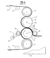
- Figure 4 illustrates a conventional embossing/laminating machine for producing two-ply paper products with nested embossments.
- An upper web 65 from an unwind stand advances over a spreader roll 66 and around an upper rubber-covered roll 67.
- An upper embossing roll 68 having projections or embossments 69 presses the upper web into the rubber-covered roll 67 to form embossments in the upper web.
- a lower web 71 is advanced from another unwind stand over a bowed roll 72 and around a lower rubber-covered roll 73.
- a lower embossing roll 74 having projections or embossments 75 presses the lower web into the rubber-covered roll 73 to form embossments in the lower web.
- Adhesive is applied to the embossments of the lower web (while they are still supported by the projections) by an adhesive-applying roll 76 which is supplied with adhesive by transfer rolls 77 and 78 and a fountain (not shown).
- the axes of rotation 68a and 74a of the upper and lower embossing rolls are parallel, and the rolls are separated to provide an open nip 80.
- the projections 69 on the upper embossing roll are offset from the projections 75 on the lower embossing roll so that the projections of the two embossing rolls mesh at the nip 80.
- the embossed upper web 65 leaves the upper embossing roll 68 at the nip 80 and meshes with the embossed lower web 71 on the lower embossing roll.
- the two webs are pressed together at a nip 81 between a rubber-covered marrying roll 82 and the projections of the lower embossing roll 74, and the adhesive on the embossments of the lower web is pressed against unembossed areas of the upper web to secure the two webs together.
- the rolls are rotatably mounted in a frame 83 of the embossing machine (shown cut away).
- FIG. 5 illustrates one embodiment of an embossing roll 85 which is formed in accordance with the invention.
- the embossing roll includes an elongated, generally cylindrical roll body 86 and a plurality of embossing plates 87.
- the particular roll illustrated includes 16 plates arranged in four longitudinally extending rows or quadrants and four circumferentially extending rows.
- the outside surfaces of the embossing plates form a cylindrical surface, and an embossing pattern is engraved on the outer surface of the plates.
- the embossing roll has a length L and a diameter D.
- the length of the embossing roll depends on the width of the web which is being embossed.
- Typical embossing rolls may have lengths of up to 2.54 m or 2.79 m (100 or 110 inches) or more and diameters of up to 45.7 cm to 50.8 cm (18 to 20 inches) or more.
- the roll body 86 includes a pair of ends 88 and journals 89 which extend away from the ends along the longitudinal axis of rotation 90 of the embossing roll.
- a vacuum rotary union 91 is mounted on the end of one of the journals and is connected to a vacuum pump or other vacuum source by vacuum line 92.
- the vacuum rotary union 91 is connected to four vacuum control valves 94 by an internal passage 95 in the journal 89.
- internal passage 95 will extend to communicate with the roll interior, which can be used as a vacuum reservoir.
- these are 3-way valves, which connect plate-suction areas either to vacuum (for holding) or to atmosphere (to release).
- Each vacuum control valve is connected through an opening 96 in the roll end 88 and an internal passage 97 in the roll body 86 to deep longitudinal and shallow transverse vacuum grooves 98 and 99 in each quadrant of the outer surface of the roll body.
- Each quadrant also includes at least one rectangular or oval groove 100 for a sealing gasket to form a vacuum suction area for holding a plate.
- two axially adjacent embossing plates are held against adjacent oval sealing glands 100a which surround longitudinal vacuum grooves 98 and transverse vacuum grooves 99.
- Adjacent longitudinal grooves 98 are connected by two shallow-angle drilled holes 98a and 98b which meet at 98c so that the vacuum areas for one longitudinal row of plates may be controlled by one valve.
- the drilled holes 98a and 98b intersect below the surface of the roll body.
- the embossing plates 87 include straight longitudinal and transverse side edges 101 and 102. However, straight-cut side edges might cause a minor disruption of the protruding elements of an engraved pattern.
- Figure 8 illustrates an embossing roll 103 which is similar to the embossing roll 85.
- the embossing plates 104 of the roll 103 have non-linear side edges 105 and 106 which avoid the important areas of the embossing pattern. While the non-linear side edges might not avoid all of the engraved portions of the plates, the disruption to the embossing pattern is substantially reduced or minimized.
- the side edges 105 and 106 are shown in zig-zag fashion for illustrative purposes only. The actual preferred contour of the non-linear edges will depend on the embossing pattern.
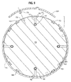
- FIG 9 is an exploded cross sectional view of an embossing roll 108 in which embossing plates 109 are removably secured to roll body 110 only by vacuum.
- a vacuum source communicates with the surface of the roll body through internal passages 111, and shallow transverse surface grooves 99 in combination with deeper longitudinal grooves 98 (see Figure 6) distribute the vacuum force over substantially the entire surface of each plate.
- Each plate is sucked by vacuum against a flexible and resilient sealing gasket 113.
- One or more cylindrical locating studs 114 extend radially inwardly from each plate. Each locating stud is inserted into a circular opening 115 in the roll body. The locating studs prevent the plates from "walking” or “creeping” under the ironing influence of the moving band of pressure which is exerted on the embossing roll by the rubber-covered backup roll.
- an electrical or mechanical sensor is used to halt the machinery if vacuum is lessened, and in addition, a check valve placed after the rotary union slows air ingress when the hose is cut.
- FIG 10 illustrates an embossing roll 117 in which embossing plates 118 are removably secured to roll body 119 by only quick-change mechanical devices.
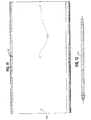
- Each plate includes two or more locating and gripping studs 120 (see also Figure 11) which cooperate with a notched rod 121 (see also Figures 12 and 13) which extends longitudinally through the entire roll body.
- the studs are cylindrical in cross section and include hook-shaped notches 122.
- each rod is provided with a semicircular notch 124 for each stud.
- the studs 120 can be inserted into the openings. The rods are then rotated one-half turn so that solid portions of the rod enter the hook-shaped notches of the studs and draw the studs into openings 123 and draw the plates against the roll body.
- each plate advantageously has a radius of curvature which is less than the radius of curvature of the roll body when the plate is not secured to the roll body.
- the curvature of the unattached plate is shown in solid outline. The plate will therefore flatten out and seat firmly against the roll body, to eliminate rattling and maintain contact despite centrifugal force in high speed operation, when it is drawn against the roll body by the rod 121.
- the curvature of the attached plate is shown in dotted outline. The bending stiffness of the plate must permit the draw-down to develop a preload higher than the centrifugal force on the plate when the embossing roll rotates.
- the rods 121 are rotatably supported in longitudinal grooves 125 which are machined in the surface of the roll body.
- the grooves extend angularly with respect to a radius of the roll body.
- One end of each rod can include a head or shoulder which bears against a shallow recess at one end of the roll body, and the other end of the rod can be threadedly engaged with a nut which bears against a shallow recess in the other end of the roll body.
- the rod can be manually rotated to a latching or unlatching position, for example by a key or wrench fitted to an appropriate feature at the threaded end, and, while its orientation is held, the rod can be locked in place by tightening the nut.
- attaching devices can be used, for example, sliding rods, screws, dovetails, any of a variety of releasable latch mechanisms, and equivalents thereof.
- the disclosed studs and rotating rods have the advantages of quick change; no loose parts which might drop to floor, or be forgotten, or work loose to damage the cooperating roll; end actuation; and easy machining into a roll surface, i.e., no long drilled holes.
- Many other sufficiently strong retaining mechanisms are possible, with or without a draw-down (leading) feature.
- projecting grippers on the roll body can engage cooperating recesses or cavities in the plates. Any such locking system must have a feature to prevent unexpected loosening due to vibration.
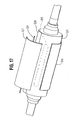
- FIG 14 illustrates an embossing roll 126 which is not in accordance with the present invention. It uses both vacuum and mechanical devices to attach embossing plates 127 to roll body 128. Each plate includes two or more locating studs 129 as described with respect to Figure 10. The studs are inserted into openings 130 in the roll body and are captured by rotatable notched rods 131 as described with respect to Figure 10. The positions of the studs relative to the openings are precise for locating purposes. However, the fit to the cooperating notched rod is loose to assure easy working. As is well known, for slidably engaging pairs, angular clearance is necessary to prevent binding in the eventuality that the plate is slightly tilted.
- the rods 131 are not designed to draw the plate down against the roll body. That is the function of the vacuum system. Rather, the rods serve to retain the plates when the vacuum is turned off or power for the vacuum source is interrupted. For safety, if this should occur while the roll is rotating, the plates must be provided with enough bending strength (by virtue of adequate thickness) to bear the cantilevered centrifugal force.
- Vacuum Loading Two vacuum regions are provided under each of the plates 127. Each vacuum region is defined by a sealing gasket 133. Vacuum communicates with each region through a longitudinal internal passage 134 and branched internal passages 135. The branched passages communicate with grooves 136 in the surface of the roll body.
- Figure 15 is an end view of the embossing roll 126 of Figure 14.
- Three-way vacuum control valves 137 are connected to the vacuum passages 138 in the journal 139 of the roll and to the longitudinal passages 134.
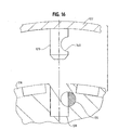
- Figure 16 illustrates the notched studs 129 of Figure 14 which are provided with circular notches 140 which are designed simply to retain the plates rather than load the plates downwardly against the roll body.
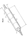
- FIGS 17 and 18 are exploded perspective views of the embossing roll 126.
- Each of the embossing plates is loaded against the embossing rolls by two vacuum regions which are defined by oval sealing gaskets 133.
- the ends of the retaining rods 131 extend beyond the ends of the roll body 128 and can be rotated by any convenient mechanism.
- the embossing plates fully cover the surfaces of an embossing roll over which the web travels so that the continuous web is embossed with the embossing pattern without interruption. Although adjacent embossing plates are separated at their edges, the side edges of the plates create little if any interruptions or discontinuities in the embossing pattern.
- a slight gap of approximately 0.25 mm (.010") or more between plates may be intentionally provided to prevent the plates from buckling, and (for the case of locating studs aligned in an axial row), slight clearance in the axial direction of the roll may be provided in the locating holes.
- any interruptions in the embossing pattern can be further reduced or minimized by contouring the side edges of the embossing plates to avoid the important areas of the embossing pattern as illustrated in Figure 7.
- the contour would be placed close to protrusion bases, where the rubber roll never penetrates.
- the plates can be urged together axially by springs or any other loading means.
- the embossing plates can be formed from steel to maximize durability.
- the thickness of the steel plates can be made sufficient so that the embossing protrusions are not flexed or fatigued by the periodic pressure of the rubber roll.
- the embossing plates for a complete embossing roll can advantageously be formed by first forming an integral steel sleeve 142.
- a steel sleeve having a wall thickness of 6.35 mm (0.25 inch) a diameter of 45.7 cm to 50.8 cm (18 to 20 inches) or more, and a length of 2.54 m to 2.79 m (100 to 110 inches) or more can be formed depending upon the dimensions of the embossing roll.
- the sleeve is prepared for later sectioning and precise mounting by drilling holes 114 at precise locations for future studs. If large holes are drilled, the holes can be tapped for installing threaded studs. Small holes can be welded closed on the outside surface of the sleeve, and the inside openings can be used to precisely position studs for welding.
- the sleeve is then engraved with the embossing pattern, for example, by match engraving which is a low-force engraving method which will not damage a thin sleeve.
- match engraving which is a low-force engraving method which will not damage a thin sleeve.
- Other possible methods are photoengraving of brass or magnesium, spray etching of steel with laser-ablated resist, laser ablation of any plate with surface of polymer or ceramic, or any other low force engraving method which is known in the art.
- the engraved sleeve is then cut into a plurality of plates.
- the thinnest possible kerf e.g., 0.2 mm - 0.51 mm (0.008-0.020 inch) will minimize disruption to pattern.
- the plates can be cut with straight side edges as indicated by the dashed lines 144 and 145 in Figure 19, or the edges can be contoured to minimize disruption of the pattern.
- the plates can be cut either manually, for example, by a jigsaw, or automatically, for example, by laser or water jet.
- the plates may be cut first and engraved second while held in position on a roll body.
- higher-force engraving methods may be used.
- This approach of engraving separate plates also offers the advantages of manufacturing curved plates by rolling flat plates; and eliminating any need for narrow-kerf sectioning.
- the embossing plates can be retrofitted to a previously formed conventional embossing roll by removing the previously engraved layer and providing the embossing roll with the vacuum and/or mechanical retaining and loading mechanisms. All of the embodiments described herein involve relatively simple surface features and short holes which can be formed in an existing embossing roll by surface machining and drilling.
- the thickness of the embossing plates can vary depending upon various criteria:
- the thickness of steel plates is preferably within the range of 3.18 mm to 6.35 mm (1/8 to 1/4 inch). Thicknesses of about 6 mm or 1/4 inch permit machining and provide sufficient plate strength at today's top operating speeds if the mechanical interlock is only in the center of the plate. If it is desired to use a thinner plate or operate at higher speeds, a more complex mechanical interlock system extending closer to the plate edges will be necessary.
- a plurality of embossing plates 165 are circumferentially or tangentially tensioned and retained on an embossing roll 166.
- Each plate includes straight side edges 167 and 168 which extend parallel to the axis of the embossing roll and curved side edges 169 and 170 which extend around the circumference of the roll and in a plane which extends transversely to the axis of the roll.
- each of the side edges 167 and 168 is provided with a cavity or groove of form 169 or 170 for mechanically loading the plate.
- Figures 21A and 21B illustrate two different options for cavities, but many other configurations can also be used.
- Figure 22 illustrates one embodiment of a retaining and loading device 172, shaped to cooperate with cavity 169, which is mounted in a cavity 173 in the embossing roll 166.
- the retaining device 172 is generally L-shaped and includes an outer end 174 and an inner end 175.
- the outer end 174 projects radially outwardly beyond the cylindrical surface of the embossing roll, and the inner end 175 is controlled by an actuator 176 which moves the retaining device between a release position illustrated in phantom outline and a loading position illustrated in solid outline.
- the actuator may be lockable in either or both positions.
- a compliant spring 178 is advantageously interposed between the actuator and the embossing roll cavity wall for providing proper tension on the embossing plates while the actuator is locked even when the plates shift or grow thermally.
- the spring allows movement of the actuator 176 as indicated by the phantom outline 176'.
- the actuator 176 advantageously controls retaining dogs 172 for an entire axial row of embossing plates.
- the retaining dogs 172 are in their release positions illustrated in phantom in Figure 22, the plates in that row can easily be removed or installed.
- the actuator 176 moves the retaining devices 172 to their retaining positions, then extends further to compress the spring, thereby circumferentially tensioning the plates and loading them firmly against the embossing roll.
- Underside vacuum on the embossing plates can also be used to load the plates firmly against the roll as previously described if proper seals are provided.
- the embossing plates can be circumferentially tensioned either by drawing the edges of adjacent plates together as illustrated in Figure 25 (first approach), or by stretching one plate edge away from the other edge as shown in Figure 28 (second approach).
- first approach transmitting tension from one plate to the next, lends itself to a very simple construction.
- removing one row of plates requires releasing both neighboring rows, thereby making a change more difficult.
- second approach tensioning axial rows of plates individually, even when neighboring rows are not yet installed, involves a little more hardware.
- a U-shaped spring clamp or clip 182 similar in function to an office "black binder clip", extends the full axial length of an embossing roll 183.
- the spring clip is positioned in an axially extending groove 184 in the embossing roll.
- the spring clip 182 includes a bottom wall 186, a pair of parallel sidewalls 187 and 188, and a plurality of upwardly and inwardly extending spring fingers 189 and 190 which are separated by notches 191.
- a pair of adjacent embossing plates 193 and 194 include axially extending side edges 195 and 196.
- the bottom surface of the plate 193 is provided with a longitudinally extending recess 197, and the bottom surface of the plate 194 is provided with a longitudinally extending recess 198.
- Wedging knobs 201 and 202 are provided in the recessed portions of the plates adjacent the longitudinal edges of the plates. The longitudinal spacing between the wedging knobs 201 and 202 correspond to the spacing between the spring fingers 189 and 190.
- the embossing plates are installed on the embossing roll by positioning the embossing plates so that the wedging knobs 201 and 202 on adjacent plates are inserted into the notches 191 in the spring clip 182.
- the spring clip is then moved axially until the spring fingers 189 and 190 engage the wedging knobs 201 and 202.
- Each pair of wedging knobs wedges apart a pair of spring fingers 189 and 190.
- the material of the spring clip 182 is selected to generate the desired clamping force, for example, 100 pounds per inch along the longitudinal edges of the embossing plates.
- Each embossing plate 205 includes one or more guide pins 206 which are provided with circular notches 207. The studs are inserted into openings 208 in the embossing roll 209 and are captured by rotatable notched rods 210 as described with respect to Figure 14.
- circumferential tensioning of the engraved plates should preferably avoid any force systems that could curl up the edges of the plates. This is conveniently effected by pulling near the mid-plane MP (Figure 25) of the plate.
- Figures 31-34 which will be explained hereinafter, illustrate some of the other methods.
- the spring clip 182 can be attached to a plunger which is reciprocated axially by a pneumatic, hydraulic or electrical actuator, attached either to the roll or to the embosser frame, which is controlled from the end of the embossing roll.
- the retaining/loading mechanism desirably exerts a tangential or a tangential-plus-inward force which stresses the plate in a direction which is tangent to the cylindrical surface of the embossing roll sufficiently to load the plate securely against the roll at the peripheral speed of the rotating embossing roll.
- Centrifugal stress in steel is calculated as: 1 MPa ⁇ ( web speed / 11.257 m / s ) 2 ( 1 psi ⁇ ( web speed / 184 feet per minute ) 2 )
- a tangential stress of 3.47 MPa (500 psi) requires 175N tangential force to be applied per linear centimetre (100 pounds tangential force to be applied per linear inch) of plate edge.
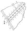
- FIG. 28-30 A preferred embodiment of a retaining/loading mechanism, representing the second approach, is illustrated in Figures 28-30.
- Each embossing plate 215 in one axial row is provided with a longitudinally extending cavity or groove 216, 217 (similar to 170 of Figure 21B) along each longitudinal edge.
- a fixed rail 219 is mounted along the full length of the embossing roll 220, and projects into the cavities 217.
- the other edges of the embossing plates are retained and loaded by an extendable retaining/loading mechanism 222 which is mounted in a longitudinally extending recess 223 along the full length of the embossing roll.
- An insert 224 is positioned in the groove 223 along the full length thereof and covers the retaining/loading device.
- the retaining/loading device 222 includes an actuator 226 and an extendable wedge 227 which is moved by the actuator 226.
- Figure 29 illustrates the actuator 226 and the wedge 227 in their release positions.
- the actuator 226 is a camming bar.
- other devices for extending and retracting the wedge 227 can be used.
- the embossing plate 215 is secured on the embossing roll by first positioning the groove 217 in the embossing plate so that it is engaged by the fixed rail 219.
- the other groove 216 is positioned relative to the extendable wedge 227 as illustrated in Figure 29.
- the cam bar 226 is then displaced axially to move the wedge 227 outwardly as illustrated in Figure 30.
- the outer end of the wedge 227 enters the groove 216 and engages the side wall 228 of the groove, thus retaining the plate.
- the wedge 227 contacts the groove wall near the midplane MP of the embossing plate, and the advancement of the wedge tip against the wall 228 provides a force component which tensions the embossing plate tangentially and in the midplane.
- the cam bar 226 is reversed to retract the wedge 227.
- the wedge retracts beneath the surface of the roll.
- below-surface retraction is not necessary for proper functioning.
- a compliant spring 230 is advantageously positioned between the cam bar 226 and either the insert 224 or the wall of the embossing roll press 223.
- the compliant spring advantageously flexes 2.54 mm (0.100 inch)or more when the actuator 226 is further extended to load the embossing plate, so that slight dimensional imprecision in the parts does not dramatically affect the final loading force.
- actuators can be used to move the wedge 227.
- a rotatable cam actuator will be discussed hereinafter.
- pneumatic, hydraulic, or electrical actuators can also be used to extend and retract the wedge 227 or slide the cam bar 226.
- a single actuator advantageously suffices for an entire longitudinal row of embossing plates, and can be moved or controlled from the end of the embossing roll.
- Figure 31 illustrates welded-on or screwed-on plate appendages rather than cavities or grooves for circumferentially tensioning an embossing plate.
- an angle 234 is attached to the embossing plate 235.
- the legs of the angle form an acute angle, and the lower leg is engaged by the wedge 236 which is extended and retracted by an actuator (not shown).
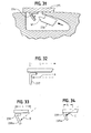
- Figures 32-34 illustrate the effects of appendage shape and size on plate bending.
- an L-shaped angle 237 is engaged by a retaining/loading device which exerts loading force in the direction of arrow A.
- the length L of bent plate is long. Applying the force nearer (short leg) reduces the bending moment.
- an angle 238 having a relatively long leg 238 is engaged by a retaining/loading device which exerts loading force in the direction of angle B.
- the bent length L is shorter.
- an angle 239 having a short leg 239a is engaged by a device which exerts loading force in the direction of arrow C. In this case length L is shorter yet.
- the angle and the height of the loading point on the appendage or angle dictates both the radial component of loading and the tendency to bend the engraving plate. If an appendage is used, preferably the direction and application point of the loading force exposes only a short segment of the seated plate to bending moments, as in Figure 34.
- One way to minimize plate-bending moment is to load the appendage with forces substantially equivalent to a pure force at the plate mid plane.
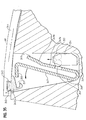
- Figure 35 illustrates a replaceable gripping appendage 242 which is trapped in a longitudinal groove 243 in the engraved plate 244.
- the appendage includes an edge 245 which applies a pure force on the engraved plate at the midplane MP of the plate so that the plate edge does not curl.
- the appendage 242 is engaged by a generally U-shaped spring clip 247 which includes a pair of legs 248 and 249.
- the leg 248 terminates in an angled end portion 250 which can be inserted into a moment-transmitting slot 251 in the appendage 242.
- the leg 249 includes a lower portion 249a which extends generally parallel to the leg 248, a relatively short angled midportion 249b which extends away from the leg 248, and a longer angled end portion 249c which extends away from the leg 248.
- Multiple pairs of friction-reducing ball bearings 252 and 253 are retained in a ball retainer 254.
- Ball 252 engages the spring leg 249, and ball 253 engages the wall of the groove in the embossing roll.
- the embossing plate is retained by camming the ball retainer upwardly.
- the leg As the ball 252 engages the angled midportion 249b of the leg 249, the leg is moved toward the appendage 242.
- the spring urges the appendage 242 to the left and exerts a tangential tensioning force on the embossing plate.
- the spring clip For proper working, the spring clip must bear against a support such as the left wall of the groove, whose reaction force eliminates plate bending. This is an example of a spring positioned between actuator and plate, rather than the actuator positioned between the spring and the plate.
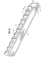
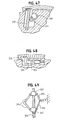
- Figures 36-39 illustrates the currently preferred and perhaps the most convenient embodiment, a refinement of that illustrated in Figures 28-30.
- This embodiment locks an entire longitudinal row of embossing plates at a time and includes features to help move each plate into the correct position for retaining and loading.
- Each embossing plate 258 is provided with grooves 259 and 260 adjacent the axial edges of the plate.
- One or more guide pins 261 extend radially inwardly from the bottom surface of each plate, and one or more detent/roller pins 262 also extend generally radially inwardly from the bottom surface of the plate.
- the embossing roll 264 is provided with a longitudinally extending sequence of fixed rails 265 for each of the longitudinal rows of embossing plates, and a row of guide pin pockets 266 and a row of detent pockets 267 for the guide pin and detent/roller pin of each plate.
- a roll-length retaining/loading mechanism 269 extends for the length of the roll and is preferably composed of a linear sequence of shorter more easily manufactured locking modules.
- the mechanism is positioned in a longitudinally extending cavity 270 for each of the longitudinal rows of embossing plates.
- An insert 271 captures the retaining/loading device and provides firm support for the plate.
- Each embossing plate is secured by first guiding it so that the cavity 260 approaches the fixed rail 265 at an angle permitting them to co-operate.
- Guidance of the embossing plate can be achieved by sliding the axial edge of the embossing plate which is adjacent the cavity 259 circumferentially of the roll body while the guide pin 261 slides along the bottom ramp of the pocket 266.
- the retaining/loading mechanism 269 remains substantially withdrawn below the surface of the roll while the embossing plate is positioned and held snugly by the detent pin 262.
- the retaining/loading mechanism is then extended, and finally exerts a tangential or a tangential-plus-inward force which stresses the plate tangentially and securely locks the plate.
- a tangential tensile stress of 3.447 MPa (500 psi) is advantageous for securing a steel embossing plate on an embossing roll which rotates at a peripheral speed of 15.24 m/s (3,000 fpm). If the average plate thickness is 0.2 inch, the required edge force is approximately 500 x 0.2 or 100 pounds per inch.
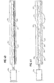
- Plate retaining and loading is effected by a movable wedge 274 which is driven out at a shallow angle by a cam bar 275 (see also Figures 40 and 41) and engages the undercut groove 259 in the plate.
- the groove 259 has an inclined face 276 ( Figure 38A), so that the force applied by the wedge is angled somewhat inwards from a tangent line.
- the reaction thrust of the cam bar is provided by a compliant spring 277 ( Figure 40), which flexes 0.100 inch or more in building up force so that slight dimensional imprecision in any of the parts does not dramatically affect the clamping.
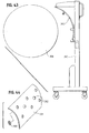
- Figures 44 and 45 illustrate replaceable embossed plugs 300 which can be used to customize embossing plates economically.
- An embossing plate 301 is provided with holes 302. While the plate is off the roll, a plug 300 can be secured in each hole, and each plug has an engraved surface 303.
- embossing plates 305 can be transported to an embossing roll 306 by a crane 280.
- the crane includes a trolley 307 which rides on an overhead rail 308 at substantially the proper height for installation.
- a vacuum lifting head 309 is supported and positioned by a guide handle 310.
- Radial preload of somewhat flexible plates is preferably achieved by circumferentially tensioning the plates, as taught by Sato.
- the tension advantageously exceeds 1.75 kN/m (10 lb/in). This approach relies on a slight degree of plate flexibility to work well.
- radial preload is effected by evacuating atmospheric air from under the plates. The seals are partially submerged into gland grooves so they do not cause runout.
- the invention is particularly suitable for continuous web embossing using deeply engraved embossing plates or dies.
- Continuous web embossing embosses one or more moving webs as illustrated in Figures 3 and 4 with a rotating embossing roll.
- Deeply engraved plates or dies have 0.040 inch or deeper engraving, so a plate thickness of greater than 0.075 inch, more likely greater than 0.125 inch is required. In order to permit the plates to be easily carried, the thickness is preferably less than 0.375 inch.
- the thickness required for deep engraving (and the cavities on the underside for the retaining mechanism) means that the plate will be almost rigid in comparison, for example, to the magnetically retained plates of Leanna U.S. Patent No. 4,216,594.
- the plates must be made precisely enough so that the available loading force can press them firmly to the roll. Any of three approaches may be used:
- the specific actuating means, and plate-cavity or plate appendage shapes, and gripping-dog shape, or motion, can be varied tremendously while still performing the disclosed function. For example, you can twist a rod, advance a screw, push a rod, or inject some air or hydraulic fluid.
- the dogs can move in translation, rotation, screw motion, or along a complex track.
- Spring means can be part of the actuator, part of the dog, part of the actuator reaction, or even part of the plate.
- a shaft to engage plate appendages and wedge against them.
- Spring compliance can be provided either by shaft bending or by bending of the plate appendage.
- a shaft to screw toggle-bars or wedge-nuts together, pressing on a compliant support.
- a shaft 310 is rotated to force cam 311 against plate appendage 312.
- a screw 314 is rotated to extend toggle bars 315 to move a retainer 316 into a groove in an embossing plate.
- the toggle bars are attached to nuts 317 which are moved toward or away from each other by the screw 314.
- a hydraulic-based concept was already disclosed in Figure 2.
- retaining means provide a mechanical interlock between a retaining mechanism and plate features (cavities, ridges, grooves, appendages) which mechanically prevents the plate from being removed, and is sufficiently strong to hold the plate close to the roll while withstanding centrifugal force in the running condition.
- mechanical retaining could involve inserting a dog into a plate groove, and locking it in place, without exerting any plate-tensioning or drawdown force.
- the plate grooves do not actually need any undercut to retain the plate, and a purely radial pin or radially extendable rail at each edge will retain the plate (since the two rails at opposite plate edges are not parallel but diverge 90 degrees in angle).
- pure radial extension of a rail cannot load a radial groove wall to place the plate in tension. This would be a good candidate for mechanical retaining and vacuum loading.
- the result of retaining is a definitely captured but otherwise loose plate.
- loading means for urging the plate firmly against the roll surface (by vacuum, by tension (advantageously generated by urging the retaining means, if they include a tangential component of motion), or by the elasticity of an intentionally misfit plate when certain load points are drawn down into conformity).
- Magnetism can load (ferrous-only) plates against the roll, but deeply engraved thick plates require strong magnets and are too rigid to be “peeled,” thus requiring expensive additional hardware to permit convenient exchange.
- roll-indexing means will ease the task of aligning any actuator (such as a hydraulic cylinder) with a retaining/loading mechanism to be actuated.
- actuator such as a hydraulic cylinder
- locking hardware will be more reliable if mechanically locked in position by a pin other or cooperating indexing means.
- the exposed ends of the retaining/loading mechanisms would advantageously be covered over during embossing to prevent the ingress of dust and dirt.
- operational interlocks such as electric eyes or micro switches may be desirable to prevent operators from mistakenly operating the embosser when the plates are improperly seated or not retained.
Landscapes
- Engineering & Computer Science (AREA)
- Mechanical Engineering (AREA)
- Shaping Of Tube Ends By Bending Or Straightening (AREA)
- Machines For Manufacturing Corrugated Board In Mechanical Paper-Making Processes (AREA)
- Supports Or Holders For Household Use (AREA)
- Vehicle Interior And Exterior Ornaments, Soundproofing, And Insulation (AREA)
- Absorbent Articles And Supports Therefor (AREA)
- Registering, Tensioning, Guiding Webs, And Rollers Therefor (AREA)
- Perforating, Stamping-Out Or Severing By Means Other Than Cutting (AREA)
- Treatment Of Fiber Materials (AREA)
- Massaging Devices (AREA)
Claims (11)
- Prägezylinder zum Prägen einer Materialbahn, der aufweist:einen lang gestreckten Zylinderkörper (166) mit einer Längsmittelachse, einer zylindrischen Mantelfläche und einem Paar Enden;eine Vielzahl von Platten (165; 193,194), die abnehmbar auf dem Zylinderkörper (166) gehaltert sind und jeweils ein Paar Kanten (195, 196), die parallel zur Achse des Zylinderkörpers verlaufen, eine mit einem Prägemuster versehene Außenfläche und eine der Mantelfläche des Zylinderkörpers zugewandte Innenfläche aufweisen, wobei die Platten (165; 193, 194) zu mehreren Reihen jeweils mit mehreren Platten angeordnet sind; undeine Rückhaltevorrichtung (172) zum mechanischen Festhalten jeder der Platten (165; 193,194) auf dem Zylinderkörper (166), wenn sie in einer zur Längsachse des Zylinderkörpers (166) rechtwinkligen Richtung zu diesem hin bewegt werden;dadurch gekennzeichnet, dass die Rückhaltevorrichtung (172) Einrichtungen aufweist, mit denen auf die Platten (193, 194) an mindestens einer ihrer Kanten (195, 196) jeweils eine Kraft aufbringbar ist, die eine bezüglich der Mantelfläche des Zylinderkörpers allgemein in Umfangsrichtung verlaufende Komponente hat, und dasseine Einrichtung (176) vorgesehen ist, mit der die Rückhaltevorrichtung (172) betätigbar ist, um die Platten (165, 193, 194) festzulegen oder zu lösen.
- Prägezylinder nach Anspruch 1 mit einer Einrichtung (172), mit der jede Reihe von Platten (165; 193, 194) mechanisch festhaltbar ist, und einer Einrichtung (176), mit der jede der Rückhaltevorrichtungen (172) betätigbar ist, um eine vollständige Reihe von Platten (165; 193,194) festzuhalten oder zu lösen.
- Prägezylinder nach Anspruch 1, dessen Betätigungseinrichtung (176) von einem Ende des Zylinderkörpers (166) her betätigbar ist.
- Prägezylinder nach Anspruch 1, dessen Rückhaltevorrichtung (227) an der Innenfläche jeder Platte (215) angreift und die Außenflächen der Platten nicht unterbricht.
- Prägezylinder nach Anspruch 4, dessen Platten in deren Innenflächen jeweils einen Hohlraum (216) enthalten, der mit der Rückhaltevorrichtung (217) zusammenwirkt.
- Prägezylinder nach Anspruch 5, dessen Rückhaltevorrichtung einen festen Anschlag (219) auf dem Zylinderkörper aufweist, der in die Hohlräume (217) der Platten positioniert wird.
- Prägezylinder nach Anspruch 4, dessen Rückhaltevorrichtung (227) für jede Reihe einen bewegbaren Keil (227) auf dem Zylinderkörper aufweist, der zwischen einer ersten Lage, in der der Keil (227) in den Hohlräumen (216) der Platten (215) der Reihe sitzt, und einer zweiten Lage verschiebbar ist, in der der Keil (227) aus den Hohlräumen (215) der Reihe herausgezogen ist.
- Prägezylinder nach Anspruch 1, dessen Platten (235) jeweils einen Ansatz (234) aufweisen, der von der Platteninnenseite einwärts vorsteht, wobei die Ansätze (234) jeweils mit einer der Rückhaltevorrichtungen (236) in Eingriff bringbar sind.
- Prägezylinder nach Anspruch 1, weiterhin mit einer Beaufschlagungseinrichtung mit Mitteln zum Aufbringen eines Unterdrucks auf die Innenflächen aller Platten.
- Prägezylinder nach Anspruch 1, bei dem die Plattenreihen zwischen den Zylinderenden verlaufen.
- Prägezylinder nach Anspruch 1, bei dem die Plattenreihen jeweils den Zylinder axial entlang verlaufen.
Priority Applications (1)
| Application Number | Priority Date | Filing Date | Title |
|---|---|---|---|
| EP05014093A EP1584457A1 (de) | 2002-05-22 | 2002-08-26 | Prägewalze mit abnehmbaren Platten |
Applications Claiming Priority (3)
| Application Number | Priority Date | Filing Date | Title |
|---|---|---|---|
| US153335 | 2002-05-22 | ||
| US10/153,335 US6716017B2 (en) | 2001-03-09 | 2002-05-22 | Embossing roll with removable plates |
| PCT/US2002/027304 WO2003099546A1 (en) | 2002-05-22 | 2002-08-26 | Embossing roll with removable plates |
Related Child Applications (2)
| Application Number | Title | Priority Date | Filing Date |
|---|---|---|---|
| EP05014093A Division EP1584457A1 (de) | 2002-05-22 | 2002-08-26 | Prägewalze mit abnehmbaren Platten |
| EP05014093.8 Division-Into | 2005-06-29 |
Publications (2)
| Publication Number | Publication Date |
|---|---|
| EP1507652A1 EP1507652A1 (de) | 2005-02-23 |
| EP1507652B1 true EP1507652B1 (de) | 2006-01-18 |
Family
ID=29582082
Family Applications (2)
| Application Number | Title | Priority Date | Filing Date |
|---|---|---|---|
| EP02757413A Expired - Lifetime EP1507652B1 (de) | 2002-05-22 | 2002-08-26 | Prägewalze mit abnehmbaren platten |
| EP05014093A Withdrawn EP1584457A1 (de) | 2002-05-22 | 2002-08-26 | Prägewalze mit abnehmbaren Platten |
Family Applications After (1)
| Application Number | Title | Priority Date | Filing Date |
|---|---|---|---|
| EP05014093A Withdrawn EP1584457A1 (de) | 2002-05-22 | 2002-08-26 | Prägewalze mit abnehmbaren Platten |
Country Status (12)
| Country | Link |
|---|---|
| US (1) | US6716017B2 (de) |
| EP (2) | EP1507652B1 (de) |
| JP (1) | JP2005530631A (de) |
| CN (1) | CN1617794A (de) |
| AT (1) | ATE315998T1 (de) |
| AU (1) | AU2002323432A1 (de) |
| BR (1) | BR0215607A (de) |
| CA (1) | CA2471612A1 (de) |
| DE (2) | DE60208799D1 (de) |
| ES (1) | ES2224906T1 (de) |
| MX (1) | MXPA04011474A (de) |
| WO (1) | WO2003099546A1 (de) |
Families Citing this family (65)
| Publication number | Priority date | Publication date | Assignee | Title |
|---|---|---|---|---|
| US6659454B1 (en) * | 2001-08-10 | 2003-12-09 | Lexmark International, Inc. | Printer exit tray and computer printer having an exit tray |
| EP1541319B1 (de) * | 2002-06-25 | 2011-10-05 | Sumitomo Bakelite Co., Ltd. | Vorrichtung und verfahren zur verarbeitung von trägerband |
| US20040040445A1 (en) * | 2002-08-28 | 2004-03-04 | Gourmet.Impression, Llc. | Enhanced food embossing roller device |
| US20050150394A1 (en) * | 2002-08-28 | 2005-07-14 | Errera Richard B. | Food embossing and impressing device |
| US7686790B2 (en) * | 2003-03-04 | 2010-03-30 | Kimberly-Clark Worldwide, Inc. | Nonlinear, undulating perimeter embossing in an absorbent article |
| US7048885B2 (en) * | 2003-08-14 | 2006-05-23 | Kimberly-Clark Worldwide, Inc. | Method and apparatus for forming an embossed article |
| US6998086B2 (en) | 2003-09-19 | 2006-02-14 | Kimberly-Clark Worldwide, Inc. | Multi-segmented embossing apparatus and method |
| US7028612B2 (en) * | 2003-12-23 | 2006-04-18 | Paper Converting Machine Company | Interchangeable embossing plates for mounting on an embossing roll |
| US7012232B1 (en) | 2004-08-31 | 2006-03-14 | Mark Gruenspecht | RF welding device |
| ITFI20040258A1 (it) * | 2004-12-10 | 2005-03-10 | Perini Fabio Spa | Dispositivo goffratore con un rullo goffratore formato da una camicia intercambiabile e contropunte di supporto |
| US8334424B2 (en) | 2004-12-22 | 2012-12-18 | Principle Business Enterprises, Inc. | Animal incontinence device |
| US7374301B1 (en) | 2005-02-20 | 2008-05-20 | Douglas Evan Simmers | Stretched membrane device |
| US20070013099A1 (en) * | 2005-07-15 | 2007-01-18 | Epoch Composite Products, Inc. | Method And Apparatus For Emobssing Manufactured Deck Boards |
| DE102006010709A1 (de) * | 2006-03-08 | 2007-09-13 | Metsä Tissue Oyj | Prägevorrichtung für mindestens zweilagige Flächenprodukte wie Toilettenpapier, Taschentücher o. dgl. |
| US20090155401A1 (en) * | 2006-03-28 | 2009-06-18 | Sang-Choll Han | Method of Forming Nanopattern and Substrate Having Pattern Formed Using the Method |
| TWI322927B (en) * | 2006-05-24 | 2010-04-01 | Ind Tech Res Inst | Roller module for microstructure thin film imprint |
| JP2007313765A (ja) * | 2006-05-26 | 2007-12-06 | Lintec Corp | 積層シート製造装置および積層シート製造方法 |
| US20080067717A1 (en) * | 2006-09-15 | 2008-03-20 | Michael Lampignano | Apparatus for creating textured concrete surfaces |
| SE530578C2 (sv) * | 2006-11-23 | 2008-07-08 | Metso Paper Inc | Pressvals för tvättning och/eller avvattning av massa och förfarande för tillverkning eller reparation av sådan pressvals |
| GB0624463D0 (en) * | 2006-12-07 | 2007-01-17 | Falcontec Ltd | Process for producing a die |
| US7789652B2 (en) * | 2006-12-22 | 2010-09-07 | N.P. Johnson Family Limited Partnership | Fresnel lens angular segment manufacturing apparatus and method |
| US7789651B2 (en) * | 2006-12-22 | 2010-09-07 | N. P. Johnson Family Limited Partnership | Presnel lens angular segment manufacturing apparatus and method |
| US7789650B2 (en) * | 2006-12-22 | 2010-09-07 | N.P. Johnson Family Limited Partnership | Fresnel lens angular segment manufacturing apparatus and method |
| US7833377B2 (en) * | 2007-01-02 | 2010-11-16 | Principle Business Enterprises, Inc. | Process for preparing an animal incontinence device |
| US20100035078A1 (en) * | 2007-01-11 | 2010-02-11 | Staudt Eric K | Embossed thermal shield and methods of construction and installation |
| JP4469385B2 (ja) * | 2007-05-31 | 2010-05-26 | 株式会社日立産機システム | 微細モールド及びその製造方法 |
| US7806677B2 (en) * | 2007-07-16 | 2010-10-05 | Velcro Industries B.V. | Molding apparatus and related systems and methods |
| KR100953953B1 (ko) * | 2008-06-03 | 2010-04-21 | 하나마이크로(주) | 임프린트 장치용 롤 금형 |
| US8192098B1 (en) | 2008-06-17 | 2012-06-05 | Stalsen LLC | Automatically loading printing device and method of printing |
| IT1391733B1 (it) * | 2008-07-21 | 2012-01-27 | Futura Spa | Dispositivo e metodo per incollare tra loro due o piu' veli o nastri di materiale cartaceo |
| EP2275259A1 (de) * | 2009-07-14 | 2011-01-19 | Pantec GS Systems AG | Druck- oder Prägewerk und Arbeitszylinder hierfür |
| US8956685B2 (en) * | 2010-02-24 | 2015-02-17 | Monosol Rx, Llc | Use of dams to improve yield in film processing |
| US8562329B2 (en) * | 2010-06-21 | 2013-10-22 | Sca Hygiene Products Ab | Embossing tool and embossed product |
| DE102010036011A1 (de) * | 2010-08-31 | 2012-03-01 | Heidelberger Druckmaschinen Ag | Braillehülse |
| US9079373B2 (en) * | 2010-10-18 | 2015-07-14 | Preco, Inc. | System and method for embossing/debossing impressionable material |
| US8900500B2 (en) | 2011-01-08 | 2014-12-02 | Black Night Enterprises, Inc. | Facet deformation minimizing fresnel lens die roller and manufacturing method |
| WO2013002734A1 (en) * | 2011-06-28 | 2013-01-03 | Agency For Science, Technology And Research | Imprinting apparatus and method |
| US8790561B2 (en) | 2011-07-18 | 2014-07-29 | Oracle International Corporation | Methods for manufacturing an embosser drum for use in pre-formatting optical tape media |
| JP5818574B2 (ja) * | 2011-08-22 | 2015-11-18 | キヤノン株式会社 | シート給送装置及び画像形成装置 |
| US8771572B2 (en) * | 2011-10-31 | 2014-07-08 | Oracle International Corporation | Methods for manufacturing an embosser drum for use in pre-formatting optical tape media |
| EP2711666A1 (de) * | 2012-09-20 | 2014-03-26 | Boegli-Gravures S.A. | Verfahren zur Herstellung eines Satzes von miteinander kooperierenden Prägewalzen und Modellvorrichtung zur Durchführung des Verfahrens |
| EP3560727A1 (de) | 2013-01-22 | 2019-10-30 | Unilin, BVBA | Verfahren und vorrichtung zur herstellung von produkten mit geprägter oberfläche, und dadurch erhaltene produkte |
| US20140264998A1 (en) | 2013-03-14 | 2014-09-18 | Q1 Nanosystems Corporation | Methods for manufacturing three-dimensional metamaterial devices with photovoltaic bristles |
| US9954126B2 (en) | 2013-03-14 | 2018-04-24 | Q1 Nanosystems Corporation | Three-dimensional photovoltaic devices including cavity-containing cores and methods of manufacture |
| US9434102B2 (en) * | 2014-07-11 | 2016-09-06 | Oracle International Corporation | Optical tape embosser drum with shim identification |
| CN104358064B (zh) * | 2014-11-05 | 2016-06-01 | 湖州宏鑫绸厂 | 一种压花机花轮 |
| CN105799226A (zh) * | 2014-12-31 | 2016-07-27 | 博斯特(上海)有限公司 | 一种瓦楞辊单元安装夹紧机构 |
| JP6930987B2 (ja) * | 2016-02-08 | 2021-09-01 | ジーピーシーピー アイピー ホールディングス エルエルシー | 紙製品を作製するためのモールディングロール |
| ES2957657T3 (es) | 2016-02-08 | 2024-01-23 | Gpcp Ip Holdings Llc | Métodos para fabricar productos de papel utilizando un rodillo de moldeo |
| US11035077B2 (en) | 2016-02-08 | 2021-06-15 | Gpcp Ip Holdings Llc | Methods of making paper products using a molding roll |
| WO2019007552A1 (en) * | 2017-07-06 | 2019-01-10 | Bobst Mex Sa | RAINING MACHINE, GROOVING CYLINDER FOR RAINING MACHINE, AND METHOD FOR RAINING SHEETS |
| US11565493B2 (en) * | 2017-07-06 | 2023-01-31 | Bobst Mex Sa | Method of creasing sheets |
| JP6785733B2 (ja) * | 2017-08-31 | 2020-11-18 | 富士フイルム株式会社 | 型ロール及び型ロールの製造方法 |
| CN108057718B (zh) * | 2017-12-15 | 2023-11-21 | 邢台邢冶机械设备有限公司 | 一种可调整轧制深度的轧辊 |
| CN108749151B (zh) * | 2018-08-13 | 2023-10-13 | 浙江美格机械股份有限公司 | 一种预浸装饰纸印涂连线压纹装置 |
| CA3116024A1 (en) * | 2020-05-20 | 2021-11-20 | Canadian Corrugated Systems | System and method for cutting sheets for use in the production of boxes |
| MX2022015935A (es) | 2020-07-03 | 2023-01-24 | Essity Hygiene & Health Ab | Rollos sin nucleo de un producto de papel tisu y metodos de fabricacion de rollos sin nucleo. |
| MX2023000183A (es) * | 2020-07-03 | 2023-04-27 | Essity Hygiene & Health Ab | Aparato y metodo para elaboracion de un producto de papel tisu. |
| US20220126392A1 (en) * | 2020-10-23 | 2022-04-28 | Health Pro Supplies Limited | Ultrasonic welding mold for mask machine capable of quickly changing customized patterns |
| US11751575B1 (en) * | 2021-06-30 | 2023-09-12 | Carol Petersen | Embossing attachment for a rolling pin |
| CN113977923B (zh) * | 2021-11-12 | 2024-05-10 | 浙江润阳新材料科技股份有限公司 | 一种发泡材料立体压花工艺 |
| ES1285312Y (es) * | 2021-12-23 | 2022-04-19 | Comercial Industrial Maqu Carton Ondulado S L | Cilindro porta-troquel para una máquina troqueladora de material laminar |
| CN115213255B (zh) * | 2022-07-15 | 2024-06-07 | 上汽通用五菱汽车股份有限公司 | 冲压件尺寸偏差调整方法、电子设备及存储介质 |
| CN115973815B (zh) * | 2023-01-04 | 2026-03-03 | 欧克科技股份有限公司 | 一种生活用纸热压花复卷生产线 |
| CN116118173B (zh) * | 2023-04-17 | 2023-07-04 | 河北传树建材科技有限公司 | 树脂瓦压花装置 |
Family Cites Families (36)
| Publication number | Priority date | Publication date | Assignee | Title |
|---|---|---|---|---|
| US1357141A (en) | 1919-11-21 | 1920-10-26 | Bibb Dandridge Hunt | Molding-machine |
| US1558206A (en) | 1922-05-26 | 1925-10-20 | Loose Wiles Biscuit Co | Die roller |
| GB237733A (en) | 1924-08-09 | 1925-08-06 | William Henry Storey | Improvements in rotary type duplicating machines |
| US1873041A (en) | 1928-07-10 | 1932-08-23 | Lancaster Asphalt Inc | Molding apparatus |
| US1883185A (en) | 1930-07-28 | 1932-10-18 | Herman G Weber | Marking roll |
| US2022681A (en) * | 1932-05-24 | 1935-12-03 | Irving Trust Co | Printing plate clamping mechanism |
| US2060082A (en) | 1935-03-13 | 1936-11-10 | Pflanze | Means for attaching printing plates to presses |
| US2958903A (en) | 1958-04-24 | 1960-11-08 | Kloeckner Humboldt Deutz Ag | Briquetting roller press |
| US3112698A (en) | 1961-01-03 | 1963-12-03 | Addressograph Multigraph | Printing machines |
| US3078796A (en) | 1961-02-06 | 1963-02-26 | Kamata Hiroyuki | Vacuum clamping of plates for a rotary press |
| US3180007A (en) | 1963-12-13 | 1965-04-27 | Eruest W Gartz | Quick change roller coating plate |
| FR1411946A (fr) * | 1964-09-04 | 1965-09-24 | Tokyo Kikai Seisakusho Ltd | Dispositif pour la fixation des plombs sur les rotatives |
| SE303765B (de) * | 1966-05-20 | 1968-09-09 | Fallert & Co Ag | |
| US3603256A (en) | 1968-07-08 | 1971-09-07 | Albert Schnellpressen | Device for fixing form saddles on the rotary press form cylinder |
| DE2055147C3 (de) | 1970-11-10 | 1975-12-04 | Maschinenfabrik Koeppern & Co Kg, 4320 Hattingen | Walzenpresse |
| US3874836A (en) | 1974-01-10 | 1975-04-01 | Education Eng Associates | Record press for duplicating pre-recorded records |
| US4005653A (en) | 1974-09-09 | 1977-02-01 | Livermore And Knight Co., Inc. | Vacuum cylinder for printing presses |
| US4116594A (en) | 1975-12-12 | 1978-09-26 | Magna-Graphics Corporation | Embossing apparatus having magnetic roller and flexible embossing plates therefor |
| US4003114A (en) | 1976-02-25 | 1977-01-18 | Armstrong Cork Company | Compressible sleeve embossing roll |
| US4056057A (en) | 1976-02-27 | 1977-11-01 | Livermore And Knight Co., Inc. | Vacuum printing cylinder construction |
| US4159677A (en) | 1977-04-25 | 1979-07-03 | Franklin G. Smith | Embosser |
| US4313378A (en) | 1980-01-24 | 1982-02-02 | Pathfinder Graphic Associates, Inc. | No-lock printing plate assembly using flexible plates |
| FR2527520A1 (fr) | 1982-05-27 | 1983-12-02 | Cuir Jean Pierre | Dispositif de fixation d'une plaque sur un cylindre |
| US4744297A (en) | 1985-09-17 | 1988-05-17 | The Ward Machinery Company | Mounting printing plates |
| US4878407A (en) | 1986-05-01 | 1989-11-07 | The Ward Machinery Company | Vacuum die mount |
| JP2672170B2 (ja) | 1990-02-22 | 1997-11-05 | キヤノン株式会社 | 光情報記憶媒体用基板の成形用ロール,製造装置及び製造方法 |
| DE4125931A1 (de) | 1991-08-05 | 1993-02-11 | Gerhardt Int As | Verfahren zur herstellung eines walzenfoermigen praegewerkzeugs |
| US5742432A (en) | 1991-12-19 | 1998-04-21 | Bianco; James S. | Apparatus for manufacture of diffraction gratings for identification means |
| US5402721A (en) | 1993-05-13 | 1995-04-04 | Comco Machinery, Inc. | Vacuum printing plate roller |
| US5505125A (en) | 1993-10-04 | 1996-04-09 | Western Printing Machinery Company | Method and apparatus for forming a rotary embossing die with a support plate |
| EP0890257A2 (de) | 1995-03-28 | 1999-01-13 | Optronics International Corporation | Universale vakuuntrommel und maske |
| US5699740A (en) | 1996-06-17 | 1997-12-23 | Creo Products Inc. | Method of loading metal printing plates on a vacuum drum |
| US6832547B2 (en) | 1996-10-16 | 2004-12-21 | Fort James Corporation | Embossing system including sleeved rolls |
| US6043836A (en) | 1997-11-24 | 2000-03-28 | Eastman Kodak Company | Vacuum drum with countersunk holes |
| US6109326A (en) | 1998-08-20 | 2000-08-29 | Paper Converting Machine Company | Embosser for producing two-ply paper products with either nested or foot-to-foot embossments |
| US6257135B1 (en) | 1999-04-19 | 2001-07-10 | Fort James Corporation | Unitary saddle for mounting multiple emboss slugs on a single emboss roll |
-
2002
- 2002-05-22 US US10/153,335 patent/US6716017B2/en not_active Expired - Fee Related
- 2002-08-26 DE DE60208799T patent/DE60208799D1/de not_active Expired - Lifetime
- 2002-08-26 BR BR0215607-5A patent/BR0215607A/pt not_active IP Right Cessation
- 2002-08-26 JP JP2004507054A patent/JP2005530631A/ja not_active Abandoned
- 2002-08-26 EP EP02757413A patent/EP1507652B1/de not_active Expired - Lifetime
- 2002-08-26 ES ES02757413T patent/ES2224906T1/es active Pending
- 2002-08-26 AT AT02757413T patent/ATE315998T1/de not_active IP Right Cessation
- 2002-08-26 CA CA002471612A patent/CA2471612A1/en not_active Abandoned
- 2002-08-26 MX MXPA04011474A patent/MXPA04011474A/es unknown
- 2002-08-26 WO PCT/US2002/027304 patent/WO2003099546A1/en not_active Ceased
- 2002-08-26 DE DE02757413T patent/DE02757413T1/de active Pending
- 2002-08-26 AU AU2002323432A patent/AU2002323432A1/en not_active Abandoned
- 2002-08-26 CN CNA028278542A patent/CN1617794A/zh active Pending
- 2002-08-26 EP EP05014093A patent/EP1584457A1/de not_active Withdrawn
Also Published As
| Publication number | Publication date |
|---|---|
| US20020197346A1 (en) | 2002-12-26 |
| JP2005530631A (ja) | 2005-10-13 |
| MXPA04011474A (es) | 2005-02-17 |
| ES2224906T1 (es) | 2005-03-16 |
| CN1617794A (zh) | 2005-05-18 |
| DE60208799D1 (de) | 2006-04-06 |
| ATE315998T1 (de) | 2006-02-15 |
| US6716017B2 (en) | 2004-04-06 |
| DE02757413T1 (de) | 2005-06-23 |
| EP1507652A1 (de) | 2005-02-23 |
| AU2002323432A1 (en) | 2003-12-12 |
| BR0215607A (pt) | 2005-03-22 |
| WO2003099546A1 (en) | 2003-12-04 |
| EP1584457A1 (de) | 2005-10-12 |
| CA2471612A1 (en) | 2003-12-04 |
Similar Documents
| Publication | Publication Date | Title |
|---|---|---|
| US6716017B2 (en) | Embossing roll with removable plates | |
| EP0796727B1 (de) | Verfahren zum Herstellen von geprägten Bahnen mit gleicher Prägungsdefinition an beiden Seiten | |
| JP6764398B2 (ja) | エンボス・ラミネート加工装置 | |
| EP1321287A3 (de) | Prägevorrichtung und -Verfahren zum Schwächen einer Materialbahn in Längsrichtung, wobei die Festigkeit in Querrichtung erhalten bleibt | |
| CN109562588B (zh) | 凸印装置及方法 | |
| IL287868B1 (en) | A system for creating cumulative sheets with flexible tools | |
| US11235430B2 (en) | Device for detachably securing modules | |
| JPH02214660A (ja) | 印刷機用インキダクト | |
| EP1370412A2 (de) | Prägewalze mit abnehmbaren platten | |
| US6845700B2 (en) | Device for mounting and removing die blankets of a rotary cutting anvil cylinder | |
| CA1215560A (en) | Device to prepare the dies of a platen press | |
| TW201811548A (zh) | 具有凸印滾輪儲存單元的凸印裝置 | |
| US6257135B1 (en) | Unitary saddle for mounting multiple emboss slugs on a single emboss roll | |
| US6361601B1 (en) | Method of applying adhesive to a patterned web and application unit for selectively applying such adhesive | |
| JP2005510381A (ja) | 交換可能なスリーブとその両端にスリーブをロックするシステムを具備したエンボスシリンダーとエンボスシリンダーを備えたエンボス加工装置 | |
| US20020060032A1 (en) | Apparatus to clamp at least one non-woven or paper sheet, methods implementing such apparatus, and article made by such methods | |
| KR200241848Y1 (ko) | 권취용 지관 고정장치 | |
| JP2008531308A (ja) | ダイカッタのブランケット・アンビルロッキングシステム | |
| EP2051857B1 (de) | Montage von nummerierungsvorrichtungen auf nummerierungszylindern | |
| EP0837990B1 (de) | Bremsvorrichtung für lineare verstelleinrichtung | |
| JPH09136745A (ja) | 巻取紙チャック | |
| KR102232024B1 (ko) | 강판 연마용 브러쉬 디스크의 정렬 및 압착 시스템 | |
| CN224116892U (zh) | 一种纸张印刷压花辊 | |
| CN101574801B (zh) | 棘轮扳手 | |
| KR102232025B1 (ko) | 연마용 브러쉬 디스크의 정렬 가이드 방법 |
Legal Events
| Date | Code | Title | Description |
|---|---|---|---|
| PUAI | Public reference made under article 153(3) epc to a published international application that has entered the european phase |
Free format text: ORIGINAL CODE: 0009012 |
|
| 17P | Request for examination filed |
Effective date: 20040924 |
|
| AK | Designated contracting states |
Kind code of ref document: A1 Designated state(s): AT BE BG CH CY CZ DE DK EE ES FI FR GB GR IE IT LI LU MC NL PT SE SK TR |
|
| AX | Request for extension of the european patent |
Extension state: AL LT LV MK RO SI |
|
| 17Q | First examination report despatched |
Effective date: 20050405 |
|
| DET | De: translation of patent claims | ||
| GRAP | Despatch of communication of intention to grant a patent |
Free format text: ORIGINAL CODE: EPIDOSNIGR1 |
|
| DAX | Request for extension of the european patent (deleted) | ||
| GRAS | Grant fee paid |
Free format text: ORIGINAL CODE: EPIDOSNIGR3 |
|
| GRAA | (expected) grant |
Free format text: ORIGINAL CODE: 0009210 |
|
| AK | Designated contracting states |
Kind code of ref document: B1 Designated state(s): AT BE BG CH CY CZ DE DK EE ES FI FR GB GR IE IT LI LU MC NL PT SE SK TR |
|
| PG25 | Lapsed in a contracting state [announced via postgrant information from national office to epo] |
Ref country code: IT Free format text: LAPSE BECAUSE OF FAILURE TO SUBMIT A TRANSLATION OF THE DESCRIPTION OR TO PAY THE FEE WITHIN THE PRESCRIBED TIME-LIMIT;WARNING: LAPSES OF ITALIAN PATENTS WITH EFFECTIVE DATE BEFORE 2007 MAY HAVE OCCURRED AT ANY TIME BEFORE 2007. THE CORRECT EFFECTIVE DATE MAY BE DIFFERENT FROM THE ONE RECORDED. Effective date: 20060118 Ref country code: SK Free format text: LAPSE BECAUSE OF FAILURE TO SUBMIT A TRANSLATION OF THE DESCRIPTION OR TO PAY THE FEE WITHIN THE PRESCRIBED TIME-LIMIT Effective date: 20060118 Ref country code: NL Free format text: LAPSE BECAUSE OF FAILURE TO SUBMIT A TRANSLATION OF THE DESCRIPTION OR TO PAY THE FEE WITHIN THE PRESCRIBED TIME-LIMIT Effective date: 20060118 Ref country code: BE Free format text: LAPSE BECAUSE OF FAILURE TO SUBMIT A TRANSLATION OF THE DESCRIPTION OR TO PAY THE FEE WITHIN THE PRESCRIBED TIME-LIMIT Effective date: 20060118 Ref country code: CH Free format text: LAPSE BECAUSE OF FAILURE TO SUBMIT A TRANSLATION OF THE DESCRIPTION OR TO PAY THE FEE WITHIN THE PRESCRIBED TIME-LIMIT Effective date: 20060118 Ref country code: AT Free format text: LAPSE BECAUSE OF FAILURE TO SUBMIT A TRANSLATION OF THE DESCRIPTION OR TO PAY THE FEE WITHIN THE PRESCRIBED TIME-LIMIT Effective date: 20060118 Ref country code: FI Free format text: LAPSE BECAUSE OF FAILURE TO SUBMIT A TRANSLATION OF THE DESCRIPTION OR TO PAY THE FEE WITHIN THE PRESCRIBED TIME-LIMIT Effective date: 20060118 Ref country code: LI Free format text: LAPSE BECAUSE OF FAILURE TO SUBMIT A TRANSLATION OF THE DESCRIPTION OR TO PAY THE FEE WITHIN THE PRESCRIBED TIME-LIMIT Effective date: 20060118 |
|
| REG | Reference to a national code |
Ref country code: GB Ref legal event code: FG4D |
|
| REG | Reference to a national code |
Ref country code: CH Ref legal event code: EP |
|
| REG | Reference to a national code |
Ref country code: IE Ref legal event code: FG4D |
|
| REF | Corresponds to: |
Ref document number: 60208799 Country of ref document: DE Date of ref document: 20060406 Kind code of ref document: P |
|
| PG25 | Lapsed in a contracting state [announced via postgrant information from national office to epo] |
Ref country code: BG Free format text: LAPSE BECAUSE OF FAILURE TO SUBMIT A TRANSLATION OF THE DESCRIPTION OR TO PAY THE FEE WITHIN THE PRESCRIBED TIME-LIMIT Effective date: 20060418 Ref country code: DK Free format text: LAPSE BECAUSE OF FAILURE TO SUBMIT A TRANSLATION OF THE DESCRIPTION OR TO PAY THE FEE WITHIN THE PRESCRIBED TIME-LIMIT Effective date: 20060418 Ref country code: SE Free format text: LAPSE BECAUSE OF FAILURE TO SUBMIT A TRANSLATION OF THE DESCRIPTION OR TO PAY THE FEE WITHIN THE PRESCRIBED TIME-LIMIT Effective date: 20060418 |
|
| PG25 | Lapsed in a contracting state [announced via postgrant information from national office to epo] |
Ref country code: DE Free format text: LAPSE BECAUSE OF FAILURE TO SUBMIT A TRANSLATION OF THE DESCRIPTION OR TO PAY THE FEE WITHIN THE PRESCRIBED TIME-LIMIT Effective date: 20060419 |
|
| PG25 | Lapsed in a contracting state [announced via postgrant information from national office to epo] |
Ref country code: ES Free format text: LAPSE BECAUSE OF FAILURE TO SUBMIT A TRANSLATION OF THE DESCRIPTION OR TO PAY THE FEE WITHIN THE PRESCRIBED TIME-LIMIT Effective date: 20060618 |
|
| PG25 | Lapsed in a contracting state [announced via postgrant information from national office to epo] |
Ref country code: PT Free format text: LAPSE BECAUSE OF FAILURE TO SUBMIT A TRANSLATION OF THE DESCRIPTION OR TO PAY THE FEE WITHIN THE PRESCRIBED TIME-LIMIT Effective date: 20060619 |
|
| NLV1 | Nl: lapsed or annulled due to failure to fulfill the requirements of art. 29p and 29m of the patents act | ||
| REG | Reference to a national code |
Ref country code: CH Ref legal event code: PL |
|
| PG25 | Lapsed in a contracting state [announced via postgrant information from national office to epo] |
Ref country code: IE Free format text: LAPSE BECAUSE OF NON-PAYMENT OF DUE FEES Effective date: 20060828 |
|
| PG25 | Lapsed in a contracting state [announced via postgrant information from national office to epo] |
Ref country code: MC Free format text: LAPSE BECAUSE OF NON-PAYMENT OF DUE FEES Effective date: 20060831 |
|
| PLBE | No opposition filed within time limit |
Free format text: ORIGINAL CODE: 0009261 |
|
| STAA | Information on the status of an ep patent application or granted ep patent |
Free format text: STATUS: NO OPPOSITION FILED WITHIN TIME LIMIT |
|
| 26N | No opposition filed |
Effective date: 20061019 |
|
| EN | Fr: translation not filed | ||
| GBPC | Gb: european patent ceased through non-payment of renewal fee |
Effective date: 20060826 |
|
| EL | Fr: translation of claims filed | ||
| PG25 | Lapsed in a contracting state [announced via postgrant information from national office to epo] |
Ref country code: GB Free format text: LAPSE BECAUSE OF NON-PAYMENT OF DUE FEES Effective date: 20060826 |
|
| PG25 | Lapsed in a contracting state [announced via postgrant information from national office to epo] |
Ref country code: FR Free format text: LAPSE BECAUSE OF FAILURE TO SUBMIT A TRANSLATION OF THE DESCRIPTION OR TO PAY THE FEE WITHIN THE PRESCRIBED TIME-LIMIT Effective date: 20070309 Ref country code: CZ Free format text: LAPSE BECAUSE OF FAILURE TO SUBMIT A TRANSLATION OF THE DESCRIPTION OR TO PAY THE FEE WITHIN THE PRESCRIBED TIME-LIMIT Effective date: 20060118 Ref country code: GR Free format text: LAPSE BECAUSE OF FAILURE TO SUBMIT A TRANSLATION OF THE DESCRIPTION OR TO PAY THE FEE WITHIN THE PRESCRIBED TIME-LIMIT Effective date: 20060419 |
|
| PG25 | Lapsed in a contracting state [announced via postgrant information from national office to epo] |
Ref country code: EE Free format text: LAPSE BECAUSE OF FAILURE TO SUBMIT A TRANSLATION OF THE DESCRIPTION OR TO PAY THE FEE WITHIN THE PRESCRIBED TIME-LIMIT Effective date: 20060118 |
|
| PG25 | Lapsed in a contracting state [announced via postgrant information from national office to epo] |
Ref country code: LU Free format text: LAPSE BECAUSE OF NON-PAYMENT OF DUE FEES Effective date: 20060826 Ref country code: TR Free format text: LAPSE BECAUSE OF FAILURE TO SUBMIT A TRANSLATION OF THE DESCRIPTION OR TO PAY THE FEE WITHIN THE PRESCRIBED TIME-LIMIT Effective date: 20060118 |
|
| PG25 | Lapsed in a contracting state [announced via postgrant information from national office to epo] |
Ref country code: FR Free format text: LAPSE BECAUSE OF FAILURE TO SUBMIT A TRANSLATION OF THE DESCRIPTION OR TO PAY THE FEE WITHIN THE PRESCRIBED TIME-LIMIT Effective date: 20060118 Ref country code: CY Free format text: LAPSE BECAUSE OF FAILURE TO SUBMIT A TRANSLATION OF THE DESCRIPTION OR TO PAY THE FEE WITHIN THE PRESCRIBED TIME-LIMIT Effective date: 20060118 |