EP1507886B1 - Verfahren und vorrichtung zur plasmabehandlung von werkstücken - Google Patents
Verfahren und vorrichtung zur plasmabehandlung von werkstücken Download PDFInfo
- Publication number
- EP1507886B1 EP1507886B1 EP03727229.1A EP03727229A EP1507886B1 EP 1507886 B1 EP1507886 B1 EP 1507886B1 EP 03727229 A EP03727229 A EP 03727229A EP 1507886 B1 EP1507886 B1 EP 1507886B1
- Authority
- EP
- European Patent Office
- Prior art keywords
- plasma
- chamber
- workpiece
- station
- chamber wall
- Prior art date
- Legal status (The legal status is an assumption and is not a legal conclusion. Google has not performed a legal analysis and makes no representation as to the accuracy of the status listed.)
- Expired - Lifetime
Links
- 238000000034 method Methods 0.000 title claims description 48
- 238000000576 coating method Methods 0.000 claims description 23
- 239000011248 coating agent Substances 0.000 claims description 19
- 230000008569 process Effects 0.000 claims description 17
- 238000009832 plasma treatment Methods 0.000 claims description 13
- 238000007789 sealing Methods 0.000 claims description 12
- 239000000126 substance Substances 0.000 claims description 9
- 235000013361 beverage Nutrition 0.000 claims description 8
- 230000008878 coupling Effects 0.000 claims description 8
- 238000010168 coupling process Methods 0.000 claims description 8
- 238000005859 coupling reaction Methods 0.000 claims description 8
- 230000004888 barrier function Effects 0.000 claims description 5
- 230000003068 static effect Effects 0.000 claims description 5
- 238000004659 sterilization and disinfection Methods 0.000 claims description 4
- 229920001169 thermoplastic Polymers 0.000 claims description 4
- 230000004913 activation Effects 0.000 claims description 3
- 239000012815 thermoplastic material Substances 0.000 claims description 3
- 239000004416 thermosoftening plastic Substances 0.000 claims description 3
- 239000002318 adhesion promoter Substances 0.000 claims description 2
- 239000011347 resin Substances 0.000 claims 2
- 229920005989 resin Polymers 0.000 claims 2
- 239000007789 gas Substances 0.000 description 11
- 238000004519 manufacturing process Methods 0.000 description 5
- 238000003780 insertion Methods 0.000 description 3
- 230000037431 insertion Effects 0.000 description 3
- 239000007788 liquid Substances 0.000 description 3
- 238000004806 packaging method and process Methods 0.000 description 3
- LIVNPJMFVYWSIS-UHFFFAOYSA-N silicon monoxide Chemical class [Si-]#[O+] LIVNPJMFVYWSIS-UHFFFAOYSA-N 0.000 description 3
- 230000001954 sterilising effect Effects 0.000 description 3
- CURLTUGMZLYLDI-UHFFFAOYSA-N Carbon dioxide Chemical compound O=C=O CURLTUGMZLYLDI-UHFFFAOYSA-N 0.000 description 2
- VYPSYNLAJGMNEJ-UHFFFAOYSA-N Silicium dioxide Chemical compound O=[Si]=O VYPSYNLAJGMNEJ-UHFFFAOYSA-N 0.000 description 2
- 238000001994 activation Methods 0.000 description 2
- 230000006835 compression Effects 0.000 description 2
- 238000007906 compression Methods 0.000 description 2
- 238000006073 displacement reaction Methods 0.000 description 2
- 230000002349 favourable effect Effects 0.000 description 2
- 230000035515 penetration Effects 0.000 description 2
- 239000004033 plastic Substances 0.000 description 2
- 229920003023 plastic Polymers 0.000 description 2
- 229910052814 silicon oxide Inorganic materials 0.000 description 2
- 230000006978 adaptation Effects 0.000 description 1
- QVGXLLKOCUKJST-UHFFFAOYSA-N atomic oxygen Chemical compound [O] QVGXLLKOCUKJST-UHFFFAOYSA-N 0.000 description 1
- 239000007767 bonding agent Substances 0.000 description 1
- 229910002092 carbon dioxide Inorganic materials 0.000 description 1
- 239000001569 carbon dioxide Substances 0.000 description 1
- 230000008859 change Effects 0.000 description 1
- 239000004020 conductor Substances 0.000 description 1
- 238000000151 deposition Methods 0.000 description 1
- 238000010586 diagram Methods 0.000 description 1
- 238000009826 distribution Methods 0.000 description 1
- 230000005484 gravity Effects 0.000 description 1
- 230000006872 improvement Effects 0.000 description 1
- 239000000463 material Substances 0.000 description 1
- 229910052760 oxygen Inorganic materials 0.000 description 1
- 239000001301 oxygen Substances 0.000 description 1
- 238000006116 polymerization reaction Methods 0.000 description 1
- 239000004065 semiconductor Substances 0.000 description 1
- 125000006850 spacer group Chemical group 0.000 description 1
- 230000007480 spreading Effects 0.000 description 1
- 238000003892 spreading Methods 0.000 description 1
- 239000000758 substrate Substances 0.000 description 1
- 230000007704 transition Effects 0.000 description 1
- 238000009827 uniform distribution Methods 0.000 description 1
Images



Classifications
-
- C—CHEMISTRY; METALLURGY
- C23—COATING METALLIC MATERIAL; COATING MATERIAL WITH METALLIC MATERIAL; CHEMICAL SURFACE TREATMENT; DIFFUSION TREATMENT OF METALLIC MATERIAL; COATING BY VACUUM EVAPORATION, BY SPUTTERING, BY ION IMPLANTATION OR BY CHEMICAL VAPOUR DEPOSITION, IN GENERAL; INHIBITING CORROSION OF METALLIC MATERIAL OR INCRUSTATION IN GENERAL
- C23C—COATING METALLIC MATERIAL; COATING MATERIAL WITH METALLIC MATERIAL; SURFACE TREATMENT OF METALLIC MATERIAL BY DIFFUSION INTO THE SURFACE, BY CHEMICAL CONVERSION OR SUBSTITUTION; COATING BY VACUUM EVAPORATION, BY SPUTTERING, BY ION IMPLANTATION OR BY CHEMICAL VAPOUR DEPOSITION, IN GENERAL
- C23C16/00—Chemical coating by decomposition of gaseous compounds, without leaving reaction products of surface material in the coating, i.e. chemical vapour deposition [CVD] processes
- C23C16/44—Chemical coating by decomposition of gaseous compounds, without leaving reaction products of surface material in the coating, i.e. chemical vapour deposition [CVD] processes characterised by the method of coating
- C23C16/4401—Means for minimising impurities, e.g. dust, moisture or residual gas, in the reaction chamber
- C23C16/4409—Means for minimising impurities, e.g. dust, moisture or residual gas, in the reaction chamber characterised by sealing means
-
- B—PERFORMING OPERATIONS; TRANSPORTING
- B08—CLEANING
- B08B—CLEANING IN GENERAL; PREVENTION OF FOULING IN GENERAL
- B08B7/00—Cleaning by methods not provided for in a single other subclass or a single group in this subclass
-
- B—PERFORMING OPERATIONS; TRANSPORTING
- B08—CLEANING
- B08B—CLEANING IN GENERAL; PREVENTION OF FOULING IN GENERAL
- B08B9/00—Cleaning hollow articles by methods or apparatus specially adapted thereto
- B08B9/08—Cleaning containers, e.g. tanks
- B08B9/20—Cleaning containers, e.g. tanks by using apparatus into or on to which containers, e.g. bottles, jars, cans are brought
- B08B9/42—Cleaning containers, e.g. tanks by using apparatus into or on to which containers, e.g. bottles, jars, cans are brought the apparatus being characterised by means for conveying or carrying containers therethrough
- B08B9/426—Grippers for bottles
-
- B—PERFORMING OPERATIONS; TRANSPORTING
- B29—WORKING OF PLASTICS; WORKING OF SUBSTANCES IN A PLASTIC STATE IN GENERAL
- B29C—SHAPING OR JOINING OF PLASTICS; SHAPING OF MATERIAL IN A PLASTIC STATE, NOT OTHERWISE PROVIDED FOR; AFTER-TREATMENT OF THE SHAPED PRODUCTS, e.g. REPAIRING
- B29C49/00—Blow-moulding, i.e. blowing a preform or parison to a desired shape within a mould; Apparatus therefor
- B29C49/42—Component parts, details or accessories; Auxiliary operations
- B29C49/4205—Handling means, e.g. transfer, loading or discharging means
- B29C49/42069—Means explicitly adapted for transporting blown article
-
- B—PERFORMING OPERATIONS; TRANSPORTING
- B65—CONVEYING; PACKING; STORING; HANDLING THIN OR FILAMENTARY MATERIAL
- B65D—CONTAINERS FOR STORAGE OR TRANSPORT OF ARTICLES OR MATERIALS, e.g. BAGS, BARRELS, BOTTLES, BOXES, CANS, CARTONS, CRATES, DRUMS, JARS, TANKS, HOPPERS, FORWARDING CONTAINERS; ACCESSORIES, CLOSURES, OR FITTINGS THEREFOR; PACKAGING ELEMENTS; PACKAGES
- B65D23/00—Details of bottles or jars not otherwise provided for
- B65D23/02—Linings or internal coatings
-
- B—PERFORMING OPERATIONS; TRANSPORTING
- B65—CONVEYING; PACKING; STORING; HANDLING THIN OR FILAMENTARY MATERIAL
- B65G—TRANSPORT OR STORAGE DEVICES, e.g. CONVEYORS FOR LOADING OR TIPPING, SHOP CONVEYOR SYSTEMS OR PNEUMATIC TUBE CONVEYORS
- B65G29/00—Rotary conveyors, e.g. rotating discs, arms, star-wheels or cones
-
- C—CHEMISTRY; METALLURGY
- C08—ORGANIC MACROMOLECULAR COMPOUNDS; THEIR PREPARATION OR CHEMICAL WORKING-UP; COMPOSITIONS BASED THEREON
- C08J—WORKING-UP; GENERAL PROCESSES OF COMPOUNDING; AFTER-TREATMENT NOT COVERED BY SUBCLASSES C08B, C08C, C08F, C08G or C08H
- C08J9/00—Working-up of macromolecular substances to porous or cellular articles or materials; After-treatment thereof
- C08J9/0004—Use of compounding ingredients, the chemical constitution of which is unknown, broadly defined, or irrelevant
-
- C—CHEMISTRY; METALLURGY
- C23—COATING METALLIC MATERIAL; COATING MATERIAL WITH METALLIC MATERIAL; CHEMICAL SURFACE TREATMENT; DIFFUSION TREATMENT OF METALLIC MATERIAL; COATING BY VACUUM EVAPORATION, BY SPUTTERING, BY ION IMPLANTATION OR BY CHEMICAL VAPOUR DEPOSITION, IN GENERAL; INHIBITING CORROSION OF METALLIC MATERIAL OR INCRUSTATION IN GENERAL
- C23C—COATING METALLIC MATERIAL; COATING MATERIAL WITH METALLIC MATERIAL; SURFACE TREATMENT OF METALLIC MATERIAL BY DIFFUSION INTO THE SURFACE, BY CHEMICAL CONVERSION OR SUBSTITUTION; COATING BY VACUUM EVAPORATION, BY SPUTTERING, BY ION IMPLANTATION OR BY CHEMICAL VAPOUR DEPOSITION, IN GENERAL
- C23C14/00—Coating by vacuum evaporation, by sputtering or by ion implantation of the coating forming material
- C23C14/04—Coating on selected surface areas, e.g. using masks
- C23C14/046—Coating cavities or hollow spaces, e.g. interior of tubes; Infiltration of porous substrates
-
- C—CHEMISTRY; METALLURGY
- C23—COATING METALLIC MATERIAL; COATING MATERIAL WITH METALLIC MATERIAL; CHEMICAL SURFACE TREATMENT; DIFFUSION TREATMENT OF METALLIC MATERIAL; COATING BY VACUUM EVAPORATION, BY SPUTTERING, BY ION IMPLANTATION OR BY CHEMICAL VAPOUR DEPOSITION, IN GENERAL; INHIBITING CORROSION OF METALLIC MATERIAL OR INCRUSTATION IN GENERAL
- C23C—COATING METALLIC MATERIAL; COATING MATERIAL WITH METALLIC MATERIAL; SURFACE TREATMENT OF METALLIC MATERIAL BY DIFFUSION INTO THE SURFACE, BY CHEMICAL CONVERSION OR SUBSTITUTION; COATING BY VACUUM EVAPORATION, BY SPUTTERING, BY ION IMPLANTATION OR BY CHEMICAL VAPOUR DEPOSITION, IN GENERAL
- C23C14/00—Coating by vacuum evaporation, by sputtering or by ion implantation of the coating forming material
- C23C14/22—Coating by vacuum evaporation, by sputtering or by ion implantation of the coating forming material characterised by the process of coating
- C23C14/50—Substrate holders
- C23C14/505—Substrate holders for rotation of the substrates
-
- C—CHEMISTRY; METALLURGY
- C23—COATING METALLIC MATERIAL; COATING MATERIAL WITH METALLIC MATERIAL; CHEMICAL SURFACE TREATMENT; DIFFUSION TREATMENT OF METALLIC MATERIAL; COATING BY VACUUM EVAPORATION, BY SPUTTERING, BY ION IMPLANTATION OR BY CHEMICAL VAPOUR DEPOSITION, IN GENERAL; INHIBITING CORROSION OF METALLIC MATERIAL OR INCRUSTATION IN GENERAL
- C23C—COATING METALLIC MATERIAL; COATING MATERIAL WITH METALLIC MATERIAL; SURFACE TREATMENT OF METALLIC MATERIAL BY DIFFUSION INTO THE SURFACE, BY CHEMICAL CONVERSION OR SUBSTITUTION; COATING BY VACUUM EVAPORATION, BY SPUTTERING, BY ION IMPLANTATION OR BY CHEMICAL VAPOUR DEPOSITION, IN GENERAL
- C23C14/00—Coating by vacuum evaporation, by sputtering or by ion implantation of the coating forming material
- C23C14/22—Coating by vacuum evaporation, by sputtering or by ion implantation of the coating forming material characterised by the process of coating
- C23C14/56—Apparatus specially adapted for continuous coating; Arrangements for maintaining the vacuum, e.g. vacuum locks
-
- C—CHEMISTRY; METALLURGY
- C23—COATING METALLIC MATERIAL; COATING MATERIAL WITH METALLIC MATERIAL; CHEMICAL SURFACE TREATMENT; DIFFUSION TREATMENT OF METALLIC MATERIAL; COATING BY VACUUM EVAPORATION, BY SPUTTERING, BY ION IMPLANTATION OR BY CHEMICAL VAPOUR DEPOSITION, IN GENERAL; INHIBITING CORROSION OF METALLIC MATERIAL OR INCRUSTATION IN GENERAL
- C23C—COATING METALLIC MATERIAL; COATING MATERIAL WITH METALLIC MATERIAL; SURFACE TREATMENT OF METALLIC MATERIAL BY DIFFUSION INTO THE SURFACE, BY CHEMICAL CONVERSION OR SUBSTITUTION; COATING BY VACUUM EVAPORATION, BY SPUTTERING, BY ION IMPLANTATION OR BY CHEMICAL VAPOUR DEPOSITION, IN GENERAL
- C23C16/00—Chemical coating by decomposition of gaseous compounds, without leaving reaction products of surface material in the coating, i.e. chemical vapour deposition [CVD] processes
- C23C16/04—Coating on selected surface areas, e.g. using masks
- C23C16/045—Coating cavities or hollow spaces, e.g. interior of tubes; Infiltration of porous substrates
-
- C—CHEMISTRY; METALLURGY
- C23—COATING METALLIC MATERIAL; COATING MATERIAL WITH METALLIC MATERIAL; CHEMICAL SURFACE TREATMENT; DIFFUSION TREATMENT OF METALLIC MATERIAL; COATING BY VACUUM EVAPORATION, BY SPUTTERING, BY ION IMPLANTATION OR BY CHEMICAL VAPOUR DEPOSITION, IN GENERAL; INHIBITING CORROSION OF METALLIC MATERIAL OR INCRUSTATION IN GENERAL
- C23C—COATING METALLIC MATERIAL; COATING MATERIAL WITH METALLIC MATERIAL; SURFACE TREATMENT OF METALLIC MATERIAL BY DIFFUSION INTO THE SURFACE, BY CHEMICAL CONVERSION OR SUBSTITUTION; COATING BY VACUUM EVAPORATION, BY SPUTTERING, BY ION IMPLANTATION OR BY CHEMICAL VAPOUR DEPOSITION, IN GENERAL
- C23C16/00—Chemical coating by decomposition of gaseous compounds, without leaving reaction products of surface material in the coating, i.e. chemical vapour deposition [CVD] processes
- C23C16/22—Chemical coating by decomposition of gaseous compounds, without leaving reaction products of surface material in the coating, i.e. chemical vapour deposition [CVD] processes characterised by the deposition of inorganic material, other than metallic material
- C23C16/30—Deposition of compounds, mixtures or solid solutions, e.g. borides, carbides, nitrides
- C23C16/40—Oxides
- C23C16/401—Oxides containing silicon
-
- C—CHEMISTRY; METALLURGY
- C23—COATING METALLIC MATERIAL; COATING MATERIAL WITH METALLIC MATERIAL; CHEMICAL SURFACE TREATMENT; DIFFUSION TREATMENT OF METALLIC MATERIAL; COATING BY VACUUM EVAPORATION, BY SPUTTERING, BY ION IMPLANTATION OR BY CHEMICAL VAPOUR DEPOSITION, IN GENERAL; INHIBITING CORROSION OF METALLIC MATERIAL OR INCRUSTATION IN GENERAL
- C23C—COATING METALLIC MATERIAL; COATING MATERIAL WITH METALLIC MATERIAL; SURFACE TREATMENT OF METALLIC MATERIAL BY DIFFUSION INTO THE SURFACE, BY CHEMICAL CONVERSION OR SUBSTITUTION; COATING BY VACUUM EVAPORATION, BY SPUTTERING, BY ION IMPLANTATION OR BY CHEMICAL VAPOUR DEPOSITION, IN GENERAL
- C23C16/00—Chemical coating by decomposition of gaseous compounds, without leaving reaction products of surface material in the coating, i.e. chemical vapour deposition [CVD] processes
- C23C16/44—Chemical coating by decomposition of gaseous compounds, without leaving reaction products of surface material in the coating, i.e. chemical vapour deposition [CVD] processes characterised by the method of coating
- C23C16/455—Chemical coating by decomposition of gaseous compounds, without leaving reaction products of surface material in the coating, i.e. chemical vapour deposition [CVD] processes characterised by the method of coating characterised by the method used for introducing gases into reaction chamber or for modifying gas flows in reaction chamber
-
- C—CHEMISTRY; METALLURGY
- C23—COATING METALLIC MATERIAL; COATING MATERIAL WITH METALLIC MATERIAL; CHEMICAL SURFACE TREATMENT; DIFFUSION TREATMENT OF METALLIC MATERIAL; COATING BY VACUUM EVAPORATION, BY SPUTTERING, BY ION IMPLANTATION OR BY CHEMICAL VAPOUR DEPOSITION, IN GENERAL; INHIBITING CORROSION OF METALLIC MATERIAL OR INCRUSTATION IN GENERAL
- C23C—COATING METALLIC MATERIAL; COATING MATERIAL WITH METALLIC MATERIAL; SURFACE TREATMENT OF METALLIC MATERIAL BY DIFFUSION INTO THE SURFACE, BY CHEMICAL CONVERSION OR SUBSTITUTION; COATING BY VACUUM EVAPORATION, BY SPUTTERING, BY ION IMPLANTATION OR BY CHEMICAL VAPOUR DEPOSITION, IN GENERAL
- C23C16/00—Chemical coating by decomposition of gaseous compounds, without leaving reaction products of surface material in the coating, i.e. chemical vapour deposition [CVD] processes
- C23C16/44—Chemical coating by decomposition of gaseous compounds, without leaving reaction products of surface material in the coating, i.e. chemical vapour deposition [CVD] processes characterised by the method of coating
- C23C16/458—Chemical coating by decomposition of gaseous compounds, without leaving reaction products of surface material in the coating, i.e. chemical vapour deposition [CVD] processes characterised by the method of coating characterised by the method used for supporting substrates in the reaction chamber
-
- C—CHEMISTRY; METALLURGY
- C23—COATING METALLIC MATERIAL; COATING MATERIAL WITH METALLIC MATERIAL; CHEMICAL SURFACE TREATMENT; DIFFUSION TREATMENT OF METALLIC MATERIAL; COATING BY VACUUM EVAPORATION, BY SPUTTERING, BY ION IMPLANTATION OR BY CHEMICAL VAPOUR DEPOSITION, IN GENERAL; INHIBITING CORROSION OF METALLIC MATERIAL OR INCRUSTATION IN GENERAL
- C23C—COATING METALLIC MATERIAL; COATING MATERIAL WITH METALLIC MATERIAL; SURFACE TREATMENT OF METALLIC MATERIAL BY DIFFUSION INTO THE SURFACE, BY CHEMICAL CONVERSION OR SUBSTITUTION; COATING BY VACUUM EVAPORATION, BY SPUTTERING, BY ION IMPLANTATION OR BY CHEMICAL VAPOUR DEPOSITION, IN GENERAL
- C23C16/00—Chemical coating by decomposition of gaseous compounds, without leaving reaction products of surface material in the coating, i.e. chemical vapour deposition [CVD] processes
- C23C16/44—Chemical coating by decomposition of gaseous compounds, without leaving reaction products of surface material in the coating, i.e. chemical vapour deposition [CVD] processes characterised by the method of coating
- C23C16/50—Chemical coating by decomposition of gaseous compounds, without leaving reaction products of surface material in the coating, i.e. chemical vapour deposition [CVD] processes characterised by the method of coating using electric discharges
-
- C—CHEMISTRY; METALLURGY
- C23—COATING METALLIC MATERIAL; COATING MATERIAL WITH METALLIC MATERIAL; CHEMICAL SURFACE TREATMENT; DIFFUSION TREATMENT OF METALLIC MATERIAL; COATING BY VACUUM EVAPORATION, BY SPUTTERING, BY ION IMPLANTATION OR BY CHEMICAL VAPOUR DEPOSITION, IN GENERAL; INHIBITING CORROSION OF METALLIC MATERIAL OR INCRUSTATION IN GENERAL
- C23C—COATING METALLIC MATERIAL; COATING MATERIAL WITH METALLIC MATERIAL; SURFACE TREATMENT OF METALLIC MATERIAL BY DIFFUSION INTO THE SURFACE, BY CHEMICAL CONVERSION OR SUBSTITUTION; COATING BY VACUUM EVAPORATION, BY SPUTTERING, BY ION IMPLANTATION OR BY CHEMICAL VAPOUR DEPOSITION, IN GENERAL
- C23C16/00—Chemical coating by decomposition of gaseous compounds, without leaving reaction products of surface material in the coating, i.e. chemical vapour deposition [CVD] processes
- C23C16/44—Chemical coating by decomposition of gaseous compounds, without leaving reaction products of surface material in the coating, i.e. chemical vapour deposition [CVD] processes characterised by the method of coating
- C23C16/50—Chemical coating by decomposition of gaseous compounds, without leaving reaction products of surface material in the coating, i.e. chemical vapour deposition [CVD] processes characterised by the method of coating using electric discharges
- C23C16/511—Chemical coating by decomposition of gaseous compounds, without leaving reaction products of surface material in the coating, i.e. chemical vapour deposition [CVD] processes characterised by the method of coating using electric discharges using microwave discharges
-
- C—CHEMISTRY; METALLURGY
- C23—COATING METALLIC MATERIAL; COATING MATERIAL WITH METALLIC MATERIAL; CHEMICAL SURFACE TREATMENT; DIFFUSION TREATMENT OF METALLIC MATERIAL; COATING BY VACUUM EVAPORATION, BY SPUTTERING, BY ION IMPLANTATION OR BY CHEMICAL VAPOUR DEPOSITION, IN GENERAL; INHIBITING CORROSION OF METALLIC MATERIAL OR INCRUSTATION IN GENERAL
- C23C—COATING METALLIC MATERIAL; COATING MATERIAL WITH METALLIC MATERIAL; SURFACE TREATMENT OF METALLIC MATERIAL BY DIFFUSION INTO THE SURFACE, BY CHEMICAL CONVERSION OR SUBSTITUTION; COATING BY VACUUM EVAPORATION, BY SPUTTERING, BY ION IMPLANTATION OR BY CHEMICAL VAPOUR DEPOSITION, IN GENERAL
- C23C16/00—Chemical coating by decomposition of gaseous compounds, without leaving reaction products of surface material in the coating, i.e. chemical vapour deposition [CVD] processes
- C23C16/44—Chemical coating by decomposition of gaseous compounds, without leaving reaction products of surface material in the coating, i.e. chemical vapour deposition [CVD] processes characterised by the method of coating
- C23C16/54—Apparatus specially adapted for continuous coating
-
- H—ELECTRICITY
- H01—ELECTRIC ELEMENTS
- H01J—ELECTRIC DISCHARGE TUBES OR DISCHARGE LAMPS
- H01J37/00—Discharge tubes with provision for introducing objects or material to be exposed to the discharge, e.g. for the purpose of examination or processing thereof
- H01J37/32—Gas-filled discharge tubes
- H01J37/32431—Constructional details of the reactor
- H01J37/32733—Means for moving the material to be treated
-
- B—PERFORMING OPERATIONS; TRANSPORTING
- B05—SPRAYING OR ATOMISING IN GENERAL; APPLYING FLUENT MATERIALS TO SURFACES, IN GENERAL
- B05D—PROCESSES FOR APPLYING FLUENT MATERIALS TO SURFACES, IN GENERAL
- B05D1/00—Processes for applying liquids or other fluent materials
- B05D1/62—Plasma-deposition of organic layers
-
- B—PERFORMING OPERATIONS; TRANSPORTING
- B29—WORKING OF PLASTICS; WORKING OF SUBSTANCES IN A PLASTIC STATE IN GENERAL
- B29C—SHAPING OR JOINING OF PLASTICS; SHAPING OF MATERIAL IN A PLASTIC STATE, NOT OTHERWISE PROVIDED FOR; AFTER-TREATMENT OF THE SHAPED PRODUCTS, e.g. REPAIRING
- B29C2791/00—Shaping characteristics in general
- B29C2791/001—Shaping in several steps
-
- B—PERFORMING OPERATIONS; TRANSPORTING
- B29—WORKING OF PLASTICS; WORKING OF SUBSTANCES IN A PLASTIC STATE IN GENERAL
- B29C—SHAPING OR JOINING OF PLASTICS; SHAPING OF MATERIAL IN A PLASTIC STATE, NOT OTHERWISE PROVIDED FOR; AFTER-TREATMENT OF THE SHAPED PRODUCTS, e.g. REPAIRING
- B29C49/00—Blow-moulding, i.e. blowing a preform or parison to a desired shape within a mould; Apparatus therefor
- B29C49/42—Component parts, details or accessories; Auxiliary operations
- B29C49/4205—Handling means, e.g. transfer, loading or discharging means
- B29C49/42073—Grippers
-
- B—PERFORMING OPERATIONS; TRANSPORTING
- B29—WORKING OF PLASTICS; WORKING OF SUBSTANCES IN A PLASTIC STATE IN GENERAL
- B29C—SHAPING OR JOINING OF PLASTICS; SHAPING OF MATERIAL IN A PLASTIC STATE, NOT OTHERWISE PROVIDED FOR; AFTER-TREATMENT OF THE SHAPED PRODUCTS, e.g. REPAIRING
- B29C49/00—Blow-moulding, i.e. blowing a preform or parison to a desired shape within a mould; Apparatus therefor
- B29C49/42—Component parts, details or accessories; Auxiliary operations
- B29C49/4205—Handling means, e.g. transfer, loading or discharging means
- B29C49/42073—Grippers
- B29C49/42075—Grippers with pivoting clamps
-
- B—PERFORMING OPERATIONS; TRANSPORTING
- B29—WORKING OF PLASTICS; WORKING OF SUBSTANCES IN A PLASTIC STATE IN GENERAL
- B29C—SHAPING OR JOINING OF PLASTICS; SHAPING OF MATERIAL IN A PLASTIC STATE, NOT OTHERWISE PROVIDED FOR; AFTER-TREATMENT OF THE SHAPED PRODUCTS, e.g. REPAIRING
- B29C49/00—Blow-moulding, i.e. blowing a preform or parison to a desired shape within a mould; Apparatus therefor
- B29C49/42—Component parts, details or accessories; Auxiliary operations
- B29C49/4205—Handling means, e.g. transfer, loading or discharging means
- B29C49/42093—Transporting apparatus, e.g. slides, wheels or conveyors
- B29C49/42095—Rotating wheels or stars
-
- B—PERFORMING OPERATIONS; TRANSPORTING
- B29—WORKING OF PLASTICS; WORKING OF SUBSTANCES IN A PLASTIC STATE IN GENERAL
- B29C—SHAPING OR JOINING OF PLASTICS; SHAPING OF MATERIAL IN A PLASTIC STATE, NOT OTHERWISE PROVIDED FOR; AFTER-TREATMENT OF THE SHAPED PRODUCTS, e.g. REPAIRING
- B29C49/00—Blow-moulding, i.e. blowing a preform or parison to a desired shape within a mould; Apparatus therefor
- B29C49/42—Component parts, details or accessories; Auxiliary operations
- B29C49/4205—Handling means, e.g. transfer, loading or discharging means
- B29C49/42093—Transporting apparatus, e.g. slides, wheels or conveyors
- B29C49/42105—Transporting apparatus, e.g. slides, wheels or conveyors for discontinuous or batch transport
-
- B—PERFORMING OPERATIONS; TRANSPORTING
- B29—WORKING OF PLASTICS; WORKING OF SUBSTANCES IN A PLASTIC STATE IN GENERAL
- B29C—SHAPING OR JOINING OF PLASTICS; SHAPING OF MATERIAL IN A PLASTIC STATE, NOT OTHERWISE PROVIDED FOR; AFTER-TREATMENT OF THE SHAPED PRODUCTS, e.g. REPAIRING
- B29C49/00—Blow-moulding, i.e. blowing a preform or parison to a desired shape within a mould; Apparatus therefor
- B29C49/42—Component parts, details or accessories; Auxiliary operations
- B29C49/4205—Handling means, e.g. transfer, loading or discharging means
- B29C49/42113—Means for manipulating the objects' position or orientation
- B29C49/42115—Inversion, e.g. turning preform upside down
-
- B—PERFORMING OPERATIONS; TRANSPORTING
- B29—WORKING OF PLASTICS; WORKING OF SUBSTANCES IN A PLASTIC STATE IN GENERAL
- B29C—SHAPING OR JOINING OF PLASTICS; SHAPING OF MATERIAL IN A PLASTIC STATE, NOT OTHERWISE PROVIDED FOR; AFTER-TREATMENT OF THE SHAPED PRODUCTS, e.g. REPAIRING
- B29C49/00—Blow-moulding, i.e. blowing a preform or parison to a desired shape within a mould; Apparatus therefor
- B29C49/42—Component parts, details or accessories; Auxiliary operations
- B29C49/42384—Safety, e.g. operator safety
-
- B—PERFORMING OPERATIONS; TRANSPORTING
- B29—WORKING OF PLASTICS; WORKING OF SUBSTANCES IN A PLASTIC STATE IN GENERAL
- B29C—SHAPING OR JOINING OF PLASTICS; SHAPING OF MATERIAL IN A PLASTIC STATE, NOT OTHERWISE PROVIDED FOR; AFTER-TREATMENT OF THE SHAPED PRODUCTS, e.g. REPAIRING
- B29C49/00—Blow-moulding, i.e. blowing a preform or parison to a desired shape within a mould; Apparatus therefor
- B29C49/42—Component parts, details or accessories; Auxiliary operations
- B29C49/64—Heating or cooling preforms, parisons or blown articles
- B29C49/68—Ovens specially adapted for heating preforms or parisons
- B29C49/6835—Ovens specially adapted for heating preforms or parisons using reflectors
-
- B—PERFORMING OPERATIONS; TRANSPORTING
- B65—CONVEYING; PACKING; STORING; HANDLING THIN OR FILAMENTARY MATERIAL
- B65G—TRANSPORT OR STORAGE DEVICES, e.g. CONVEYORS FOR LOADING OR TIPPING, SHOP CONVEYOR SYSTEMS OR PNEUMATIC TUBE CONVEYORS
- B65G2201/00—Indexing codes relating to handling devices, e.g. conveyors, characterised by the type of product or load being conveyed or handled
- B65G2201/02—Articles
- B65G2201/0235—Containers
- B65G2201/0244—Bottles
-
- C—CHEMISTRY; METALLURGY
- C08—ORGANIC MACROMOLECULAR COMPOUNDS; THEIR PREPARATION OR CHEMICAL WORKING-UP; COMPOSITIONS BASED THEREON
- C08J—WORKING-UP; GENERAL PROCESSES OF COMPOUNDING; AFTER-TREATMENT NOT COVERED BY SUBCLASSES C08B, C08C, C08F, C08G or C08H
- C08J2300/00—Characterised by the use of unspecified polymers
- C08J2300/14—Water soluble or water swellable polymers, e.g. aqueous gels
Definitions
- the invention relates to a method for plasma treatment of workpieces, in which the workpiece is inserted into an at least partially evacuatable plasma chamber of a treatment station and in which at least a part of the treatment station is moved relative to at least one further part to assist handling of the workpieces.
- the invention further relates to a device for plasma treatment of workpieces, which has at least one evacuatable plasma chamber for receiving the workpieces and in which the plasma chamber is arranged in the region of a treatment station, and in which the plasma chamber of a chamber bottom, a chamber lid and an outer lateral chamber wall is limited.
- Such methods and devices are used, for example, for plastics with surface coatings Mistake.
- such methods and devices are already known for coating inner or outer surfaces of containers intended for packaging liquids.
- facilities for plasma sterilization are known.
- a plasma chamber for the inner coating of PET bottles is described.
- the bottles to be coated are raised by a movable floor in a plasma chamber and brought in the area of a bottle mouth with an adapter in combination. Through the adapter, an evacuation of the bottle interior can take place.
- a hollow lance is inserted through the adapter into the interior of the bottles to supply process gas. Ignition of the plasma occurs using a microwave.
- a feeder is described to evacuate a bottle interior and to supply with process gas.
- a plasma chamber is described in which the bottles are introduced by a movable lid which has been previously connected to a mouth region of the bottles.
- the PCT-WO 00/58631 also already shows the arrangement of plasma stations on a rotating wheel and describes for such an arrangement a group assignment of vacuum pumps and plasma stations to a favorable evacuation of the chambers and the interiors of the To support bottles.
- the coating of several containers in a common plasma station or a common cavity is mentioned.
- barrier layers prevent the penetration of oxygen into the packaged liquids and leakage of carbon dioxide in CO 2 -containing liquids.
- Object of the present invention is therefore to provide a method of the initially mentioned type such that a handling of the treated workpieces with high Speed and high reliability is supported.
- a sleeve-shaped outer chamber wall is movable relative to a chamber bottom and relative to a chamber lid and positioned that a workpiece is treated from a thermoplastic material and that a beverage bottle is treated as a workpiece that the positioning in a vertical direction is carried out and that the chamber bottom and the chamber lid are left relative to a station frame of the plasma station in a static positioning and that the chamber wall is sealed relative to the chamber lid.
- Another object of the present invention is to construct a device of the aforementioned type such that a simple motion kinematics of the workpieces to be treated is supported.
- the chamber wall sleeve-shaped and arranged both relative to the chamber bottom and relative to the chamber lid and that the plasma station is formed for coating a workpiece in the form of a beverage bottle of a thermoplastic material, that the chamber wall in a vertical Direction can be positioned by a displacement of the chamber wall and that the chamber bottom and the chamber lid are arranged relative to a station frame of the plasma station in a static positioning and that the chamber wall is sealed relative to the chamber lid.
- the sleeve-shaped chamber wall which can be positioned relative to the chamber bottom and the chamber lid, it is possible to transport the workpieces to be treated at a substantially constant height level. It is thereby saved the time for a height adjustment of the workpieces to be carried out according to the prior art as well as the design effort required for this purpose.
- the chamber bottom and the chamber lid remain at the same height level, so that with simple design means in the chamber lid a microwave generator for igniting the plasma and .in the chamber bottom feeder for the vacuum and the process gas can be arranged. All resource supplies and power supplies can thus be done over fixed lines and it clutches or in terms of their lifetime critical flexible lines are avoided.
- the procedural sequence in the handling of the workpieces is such that the sliding sleeve first is moved so that an insertion of the workpiece to be coated is made possible in the chamber.
- the sleeve-shaped chamber wall is moved into the work positioning and after sufficient evacuation and supply of the process gas, the plasma coating or another plasma treatment can be performed after a microwave ignition.
- the sleeve-shaped chamber wall is moved again and the treated workpiece can be removed and a new workpiece to be treated can be used.
- a resource supply and a power supply with simple structural design is supported by the fact that the chamber bottom and the chamber lid are left in a static positioning relative to a station frame of the plasma station.
- a device technically simple realization is also supported by the fact that process gas is supplied through the chamber bottom.
- a fast and uniform distribution of the process gas in an interior of the workpiece can be achieved be that the process gas is fed through a lance into an interior of the workpiece.
- the chamber wall is sealed relative to the chamber bottom.
- a low-wear performing a plurality of opening and closing operations of the plasma chamber is assisted in that the sealing is performed by a seal connected to the chamber wall.
- the seal can also be arranged in the region of the chamber bottom.
- a further improved sealing quality can be achieved in that the sealing between an inner flange of the chamber wall and a flange of the Kammerdekkels is performed.
- microwaves generated by a microwave generator be introduced into the cavity in the region of the chamber lid.
- microwave generator is connected by a coupling channel with the interior of the cavity.
- a typical application is that a workpiece is treated from a thermoplastic.
- a high production rate with high reliability and high product quality can be achieved by transferring the plasma station from a rotating plasma wheel from an input positioning to an output positioning.
- a chamber wall provided for providing at least two cavities is positioned.
- a typical application is defined by plasma coating as the plasma treatment.
- the plasma treatment be performed using a low pressure plasma.
- a good surface adhesion is supported by the fact that at least partially organic substances are deposited by the plasma.
- Particularly advantageous use properties in workpieces for packaging foodstuffs can be achieved by at least partially depositing inorganic substances through the plasma.
- a bonding agent for improving adhesion of the substance is deposited on a surface of the workpiece.
- High productivity can be assisted by treating at least two workpieces simultaneously in a common cavity.
- Another field of application is that a plasma sterilization is carried out as a plasma treatment.
- surface activation of the workpiece is performed as a plasma treatment.
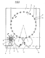
- a plasma module (1) can be seen, which is provided with a rotating plasma wheel (2). Along a circumference of the plasma wheel (2) a plurality of plasma stations (3) are arranged. The plasma stations (3) are provided with cavities (4) or plasma chambers (17) for receiving workpieces (5) to be treated.
- the workpieces (5) to be treated are supplied to the plasma module (1) in the region of an input (6) and forwarded via a separating wheel (7) to a transfer wheel (8) equipped with positionable support arms (9).
- the support arms (9) are arranged pivotable relative to a base (10) of the transfer wheel (8), so that a change in the distance of the workpieces (5) relative to each other can be performed.
- the input wheel (11) transfers the workpieces (5) to be treated to the plasma wheel (2).
- the treated workpieces (5) are removed from the area of the plasma wheel (2) by an output wheel (12) and transferred to the area of an output line (13).
- the plasma stations (3) are each equipped with two cavities (4) and plasma chambers (17).
- two workpieces (5) can be treated simultaneously.
- this is thought to delimit the partial cavities at least by separate Mikrowelleneinkopplept against each other.
- Fig. 3 shows a perspective view of a plasma module (1) with partially constructed plasma wheel (2).
- the plasma stations (3) are arranged on a support ring (14), which is formed as part of a rotary joint and mounted in the region of a machine base (15).
- the plasma stations (3) each have a station frame (16) which holds plasma chambers (17).
- the plasma chambers (17) have cylindrical chamber walls (18) and microwave generators (19).
- a rotary distributor (20) is arranged, via which the plasma stations (3) are supplied with resources and energy.
- ring lines (21) can be used.
- the workpieces (5) to be treated are shown below the cylindrical chamber walls (18). Parts of the plasma chambers (17) are not shown for simplicity.
- Fig. 4 shows a plasma station (3) in a perspective view. It can be seen that the station frame (16) is provided with guide rods (23) on which a carriage (24) for holding the cylindrical chamber wall (18) is guided. Fig. 4 shows the carriage (24) with chamber wall (18) in a raised state, so that the workpiece (5) is released.
- the microwave generator (19) is connected via a deflection (25) and an adapter (26) to a coupling channel (27), which opens into the plasma chamber (17).
- the microwave generator (19) coupled both directly in the region of the Kammerdekkels (31) and via a spacer element to the chamber lid (31) with a predetermined distance to the chamber lid (31) and thus in a larger surrounding area of the chamber lid (31) ,
- the adapter (26) has the function of a transition element and the coupling channel (27) is formed as a coaxial conductor.
- a quartz glass window is arranged in the region of an opening of the coupling channel (27) in the chamber lid (31) .
- the deflection (25) is designed as a waveguide.
- the workpiece (5) is positioned by a holding element (28), which is arranged in the region of a chamber bottom (29).
- the chamber bottom (29) is formed as part of a chamber base (30).
- Another variant is to attach the chamber base (30) directly to the station frame (16). In such an arrangement, it is for example also possible to carry out the guide rods (23) in two parts in the vertical direction.
- Fig. 5 shows a front view of the plasma station (3) according to Fig. 3 in a closed state of the plasma chamber (17).
- the carriage (24) with the cylindrical chamber wall (18) is in this case opposite to the positioning in Fig. 4 lowered, so that the chamber wall (18) is moved against the chamber bottom (29). In this positioning state, the plasma coating can be performed.
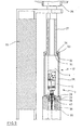
- Fig. 6 shows in a vertical sectional view of the arrangement according to Fig. 5 , It can be seen in particular that the coupling channel (27) opens into a chamber lid (31) having a laterally projecting flange (32). In the region of the flange (32) a seal (33) is arranged, which is acted upon by an inner flange (34) of the chamber wall (18). In a lowered state of the chamber wall (18), this results in a sealing of the chamber wall (18) relative to the chamber lid (31). A further seal (35) is arranged in a lower region of the chamber wall (18), in order to ensure a seal here relative to the chamber bottom (29).
- a hollow lance (36) is arranged in the region of the chamber head (30) and can be moved into the interior of the workpiece (5).
- a lance carriage (37) which can be positioned along the guide rods (23).
- a process gas channel (38) which in the in Fig. 6 shown raised positioning with a gas port (39) of the chamber base (30) is coupled.
- FIGS. 7 and 8 show the arrangement according to Fig. 5 and Fig. 6 in a raised state of the chamber wall (18). In this positioning state of the chamber wall (18), it is easily possible to remove the treated workpiece (5) from the area of the plasma station (3) and to insert a new workpiece (5) to be treated. As an alternative to the positioning of the chamber wall (18) shown in the drawings in an upwardly opened state of the plasma chamber (17), it is also possible to carry out the opening process by displacing a structurally modified sleeve-shaped chamber wall in a vertical downward direction.
- the coupling channel (27) has a cylindrical configuration and is arranged substantially coaxially with the chamber wall (18).
- Fig. 9 shows the vertical section according to Fig. 6 in an enlarged partial representation in an environment of the chamber wall (18).
- the inner flange (34) of the chamber wall (18) via the flange (32) of the chamber lid (31) and the holder of the workpiece (5) by the holding element (28).
- the lance (36) is passed through a recess (40) of the holding element (28).
- the fixation of the workpiece (5) by the holding element (28) is in the enlarged representation in FIG FIG. 10 to recognize.
- the holding element (28) is inserted into a guide sleeve (41), which is provided with a spring chamber (42).
- a compression spring (43) is inserted, which braces an outer flange (44) of the holding element (28) relative to the guide sleeve (41).
- a typical treatment process is explained below using the example of a coating process and carried out such that first the workpiece (5) using the input wheel (11) is transported to the plasma wheel (2) and that in a pushed-up state of the sleeve-like chamber wall (18) inserting of the workpiece (5) into the plasma station (3). After completion of the insertion process, the chamber wall (18) is lowered into its sealed positioning and initially carried out simultaneously an evacuation of both the cavity (4) and an interior of the workpiece (5).
- the lance (36) is retracted into the interior of the workpiece (5) and by a displacement of the holding element (28) a foreclosure of the interior of the workpiece (5) relative to the interior of the cavity ( 4) carried out. It is also possible to move the lance (36) into the workpiece (5) in synchronism with the beginning of the evacuation of the interior of the cavity. The pressure in the interior of the workpiece (5) is then further lowered. In addition, it is also intended to carry out the positioning movement of the lance (36) at least partially already parallel to the positioning of the chamber wall (18). After reaching a sufficiently low negative pressure process gas is introduced into the interior of the workpiece (5) and ignited with the aid of the microwave generator (19) the plasma. In particular, it is envisaged to deposit both an adhesion promoter on an inner surface of the workpiece (5) and the actual barrier layer of silicon oxides with the aid of the plasma.
- the lance (36) is again removed from the interior of the workpiece (5) and the plasma chamber (17) and the interior of the workpiece (5) are vented.
- the chamber wall (18) is raised again to perform a removal of the coated workpiece (5) and an input of a new workpiece to be coated (5).
- exterior coatings, sterilizations or surface activations can also be carried out.
- a positioning of the chamber wall (18), the sealing element (28) and / or the lance (36) can be carried out using different drive units.
- it is intended to realize a cam control in support of an exact coordination of movement with a rotation of the plasma wheel (2).
- the cam control may for example be designed such that along a circumference of the plasma wheel (2) control cams are arranged along which cam rollers are guided. The cam rollers are coupled to the respective components to be positioned.
Landscapes
- Chemical & Material Sciences (AREA)
- Engineering & Computer Science (AREA)
- Mechanical Engineering (AREA)
- Chemical Kinetics & Catalysis (AREA)
- Materials Engineering (AREA)
- Organic Chemistry (AREA)
- Metallurgy (AREA)
- General Chemical & Material Sciences (AREA)
- Physics & Mathematics (AREA)
- Plasma & Fusion (AREA)
- Inorganic Chemistry (AREA)
- Medicinal Chemistry (AREA)
- Polymers & Plastics (AREA)
- Health & Medical Sciences (AREA)
- Manufacturing & Machinery (AREA)
- Analytical Chemistry (AREA)
- Chemical Vapour Deposition (AREA)
- Plasma Technology (AREA)
Description
- Die Erfindung betrifft ein Verfahren zur Plasmabehandlung von Werkstücken, bei dem das Werkstück in eine zumindest teilweise evakuierbare Plasmakammer einer Behandlungsstation eingesetzt wird und bei dem zur Unterstützung einer Handhabung der Werkstücke mindestens ein Teil der Behandlungsstation relativ zu mindestens einem weiteren Teil bewegt wird.
- Die Erfindung betrifft darüber hinaus eine Vorrichtung zur Plasmabehandlung von Werkstücken, die mindestens eine evakuierbare Plasmakammer zur Aufnahme der Werkstücke aufweist und bei der die Plasmakammer im Bereich einer Behandlungsstation angeordnet ist, sowie bei der die Plasmakammer von einem Kammerboden, einem Kammerdeckel sowie einer äußeren seitlichen Kammerwandung begrenzt ist.
- Derartige Verfahren und Vorrichtungen werden beispielsweise eingesetzt, um Kunststoffe mit Oberflächenbeschichtungen zu versehen. Insbesondere sind auch bereits derartige Verfahren und Vorrichtungen bekannt, um innere oder äußere Oberflächen von Behältern zu beschichten, die zur Verpackung von Flüssigkeiten vorgesehen sind. Darüber hinaus sind Einrichtungen zur Plasmasterilisation bekannt.
- In der
PCT-WO 95/22413 - Aus dieser Veröffentlichung ist es auch bereits bekannt, eine Mehrzahl von Plasmakammern auf einem rotierenden Rad anzuordnen. Hierdurch wird eine hohe Produktionsrate von Flaschen je Zeiteinheit unterstützt.
- In der
EP-OS 10 10 773 PCT-WO 01/31680 - Die
PCT-WO 00/58631 - Eine weitere Anordnung zur Durchführung einer Innenbeschichtung von Flaschen wird in der
PCT-WO 99/17334 - Bei der überwiegenden Anzahl der bekannten Verfahren werden zur Verbesserung von Barriereeigenschaften des thermoplastischen Kunststoffmaterials durch das Plasma erzeugte Behälterschichten aus Siliziumoxiden mit der allgemeinen chemischen Formel SiOx verwendet. Derartige Barriereschichten verhindern ein Eindringen von Sauerstoff in die verpackten Flüssigkeiten sowie ein Austreten von Kohlendioxid bei CO2-haltigen Flüssigkeiten.
- Aus der
U.S. 5,084,125 A ist es bekannt, innerhalb eines metallischen Gehäuses einer Plasmakammer eine verschiebliche Hülse aus Quarzglas zu verwenden. Die Vorrichtung dient zur Beschichtung von Halbleitersubstraten. - Die bislang bekannten Verfahren und Vorrichtungen sind noch nicht in ausreichender Weise dafür geeignet, für eine Massenproduktion eingesetzt zu werden, bei der sowohl ein geringer Beschichtungspreis je Werkstück als auch eine hohe Produktionsgeschwindigkeit erreicht werden muß.
- Aufgabe der vorliegenden Erfindung ist es daher, ein Verfahren der einleitend genannten Art derart anzugeben, daß eine Handhabung der zu behandelnden Werkstücke mit hoher Geschwindigkeit und großer Zuverlässigkeit unterstützt wird.
- Diese Aufgabe wird erfindungsgemäß dadurch gelöst, daß eine hülsenförmige äußere Kammerwandung relativ zu einem Kammerboden sowie relativ zu einem Kammerdeckel beweglich ist und positioniert wird, daß ein Werkstück aus einem thermoplastischen Kunststoff behandelt wird und daß als Werkstück eine Getränkeflasche behandelt wird, daß die Positionierung in einer vertikalen Richtung durchgeführt wird und daß der Kammerboden und der Kammerdeckel relativ zu einem Stationsrahmen der Plasmastation in einer statischen Positionierung belassen werden und daß die Kammerwandung relativ zum Kammerdeckel abgedichtet wird.
- Weitere Aufgabe der vorliegenden Erfindung ist es, eine Vorrichtung der einleitend genannten Art derart zu konstruieren, daß eine einfache Bewegungskinematik der zu behandelnden Werkstücke unterstützt wird.
- Diese Aufgabe wird erfindungsgemäß dadurch gelöst, daß die Kammerwandung hülsenförmig ausgebildet und sowohl relativ zum Kammerboden als auch relativ zum Kammerdeckel beweglich angeordnet ist und daß die Plasmastation zur Beschichtung eines Werkstückes in Form einer Getränkeflasche aus einem thermoplastischen Material ausgebildet ist, daß die Kammerwandung in einer vertikalen Richtung durch eine Verschiebung der Kammerwandung positionierbar ist und daß der Kammerboden und der Kammerdeckel relativ zu einem Stationsrahmen der Plasmastation in einer statischen Positionierung angeordnet sind und daß die Kammerwandung relativ zum Kammerdeckel abgedichtet ist.
- Durch die relativ zum Kammerboden und zum Kammerdeckel positionierbare Anordnung der hülsenförmigen Kammerwandung ist es möglich, die zu behandelnden Werkstücke auf einem im wesentlichen gleichbleibenden Höhenniveau zu transportieren. Es wird hierdurch die Zeit für eine gemäß dem Stand der Technik durchzuführende Höhenpositionierung der Werkstücke sowie der hierfür erforderliche konstruktive Aufwand eingespart. Der Kammerboden sowie der Kammerdeckel bleiben auf einem gleichen Höhenniveau angeordnet, so daß mit konstruktiv einfachen Mitteln im Bereich des Kammerdeckels ein Mikrowellengenerator zur Zündung des Plasmas und.im Bereich des Kammerbodens Zuführeinrichtungen für das Vakuum sowie das Prozeßgas angeordnet werden können. Alle Betriebsmittelzuführungen sowie Energieversorgungen können somit über feste Leitungen erfolgen und es werden Kupplungen oder im Hinblick auf ihre Lebensdauer kritische flexible Leitungen vermieden.
- Der verfahrenstechnische Ablauf bei der Handhabung der Werkstücke erfolgt derart, daß die verschiebliche Hülse zunächst derart verschoben wird, daß ein Einsetzen des zu beschichtenden Werkstückes in die Kammer ermöglicht wird. Nach einem Einsetzen des Werkstückes wird die hülsenförmige Kammerwandung in die Arbeitspositionierung verschoben und nach einer ausreichenden Evakuierung sowie Zuführung des Prozeßgases kann nach einer Mikrowellenzündung die Plasmabeschichtung oder eine andere Plasmabehandlung durchgeführt werden. Nach einem Abschluß der Behandlung wird die hülsenförmige Kammerwandung erneut verschoben und das behandelte Werkstück kann entnommen sowie ein neues zu behandelndes Werkstück eingesetzt werden.
- Eine günstige Schwerkrafteinleitung wird dadurch unterstützt, daß die Positionierung in einer vertikalen Richtung durchgeführt wird.
- Eine Betriebsmittelzuführung sowie eine Energieversorgung bei einfacher konstruktiver Gestaltung wird dadurch unterstützt, daß der Kammerboden und der Kammerdeckel relativ zu einem Stationsrahmen der Plasmastation in einer statischen Positionierung belassen werden.
- Bei einer Beschichtung von hohlen Werkstücken, die mit ihrer Mündung nach unten angeordnet sind, erweist es sich als vorteilhaft, daß eine Evakuierung einer Kavität der Plasmastation durch den Kammerboden hindurch erfolgt.
- Eine gerätetechnisch einfache Realisierung wird ebenfalls dadurch unterstützt, daß durch den Kammerboden hindurch Prozeßgas zugeführt wird.
- Eine schnelle und gleichmäßige Verteilung des Prozeßgases in einem Innenraum des Werkstückes kann dadurch erreicht werden, daß das Prozeßgas durch eine Lanze hindurch in einen Innenraum des Werkstückes zugeführt wird.
- Zur Vermeidung eines Eindringens eines Umgebungsdruckes in die evakuierte Plasmakammer wird vorgeschlagen, daß die Kammerwandung relativ zum Kammerboden abgedichtet wird.
- Eine verschleißarme Durchführung einer Vielzahl von Öffnungs- und Schließvorgängen der Plasmakammer wird dadurch unterstützt, daß die Abdichtung von einer mit der Kammerwandung verbundenen Dichtung durchgeführt wird. Alternativ kann die Dichtung aber auch im Bereich des Kammerbodens angeordnet sein.
- Ebenfalls wird zur Gewährleistung einer ausreichenden Abdichtung der Plasmakammer vorgeschlagen, daß die Kammerwandung relativ zum Kammerdeckel abgedichtet wird.
- Auch bei der oberen Abdichtung der Plasmakammer kann eine hohe Abdichtungsqualität sowie ein geringer Verschleiß dadurch erreicht werden, daß die Abdichtung von einer im Bereich des Kammerdeckels angeordneten Dichtung durchgeführt wird.
- Eine nochmals verbesserte Abdichtungsqualität kann dadurch erreicht werden, daß die Abdichtung zwischen einem Innenflansch der Kammerwandung und einem Flansch des Kammerdekkels durchgeführt wird.
- Zur Unterstützung einer steuerbaren Zündung des Plasmas wird vorgeschlagen, daß im Bereich des Kammerdeckels von einem Mikrowellengenerator erzeugte Mikrowellen in die Kavität eingeleitet werden.
- Eine Anpassung der Mikrowellenzuführung an konkret vorliegende Einsatzbedingungen wird dadurch erleichtert, daß der Mikrowellengenerator von einem Kopplungskanal mit dem Innenraum der Kavität verbunden wird.
- Eine typische Anwendung besteht darin, daß ein Werkstück aus einem thermoplastischen Kunststoff behandelt wird.
- Insbesondere ist daran gedacht daß ein Innenraum des Werkstückes behandelt wird.
- Ein umfangreiches Anwendungsgebiet wird dadurch erschlossen, daß als Werkstück ein Behälter behandelt wird.
- Insbesondere ist dabei daran gedacht, daß als Werkstück eine Getränkeflasche behandelt wird.
- Eine hohe Produktionsrate bei großer Zuverlässigkeit und hoher Produktqualität kann dadurch erreicht werden, daß die Plasmastation von einem rotierenden Plasmarad von einer Eingabepositionierung in eine Ausgabepositionierung überführt wird.
- Eine Vergrößerung der Produktionskapazität bei nur geringfügig gesteigertem gerätetechnischen Aufwand kann dadurch erreicht werden, daß von einer Plasmastation mehrere Kavitäten bereitgestellt werden.
- Bei einer gleichzeitigen Beschichtung von mehreren Werkstücken ist insbesondere daran gedacht, daß eine zur Bereitstellung von mindestens zwei Kavitäten vorgesehene Kammerwandung positioniert wird.
- Eine typische Anwendung wird dadurch definiert, daß als Plasmabehandlung eine Plasmabeschichtung durchgeführt wird.
- Insbesondere ist daran gedacht, daß die Plasmabehandlung unter Verwendung eines Niederdruckplasmas durchgeführt wird.
- Bei einer Beschichtung von Werkstücken aus Kunststoff erweist es sich als vorteilhaft, daß eine Plasmapolymerisation durchgeführt wird.
- Eine gute Oberflächenhaftung wird dadurch unterstützt, daß durch das Plasma mindestens zum Teil organische Substanzen abgeschieden werden.
- Besonders vorteilhafte Verwendungseigenschaften bei Werkstücken zur Verpackung von Lebensmitteln können dadurch erreicht werden, daß durch das Plasma mindestens zum Teil anorganische Substanzen abgeschieden werden.
- Bei der Behandlung von Verpackungen ist insbesondere daran gedacht, daß durch das Plasma eine Substanz zur Verbesserung von Barriereeigenschaften des Werkstückes abgeschieden wird.
- Zur Unterstützung einer hohen Gebrauchsqualität wird vorgeschlagen, daß zusätzlich ein Haftvermittler zur Verbesserung eines Anhaftens der Substanz auf einer Oberfläche des Werkstückes abgeschieden wird.
- Eine hohe Produktivität kann dadurch unterstützt werden, daß in einer gemeinsamen Kavität mindestens zwei Werkstücke gleichzeitig behandelt werden.
- Ein weiteres Anwendungsgebiet besteht darin, daß als Plasmabehandlung eine Plasmasterilisation durchgeführt wird.
- Ebenfalls ist daran gedacht, daß als Plasmabehandlung eine Oberflächenaktivierung des Werkstückes durchgeführt wird.
- In den Zeichnungen sind Ausführungsbeispiele der Erfindung schematisch dargestellt. Es zeigen:
- Fig. 1
- Eine Prinzipskizze einer Mehrzahl von Plasmakammern, die auf einem rotierenden Plasmarad angeordnet sind und bei der das Plasmarad mit Eingabe- und Ausgaberädern gekoppelt ist.
- Fig. 2
- eine Anordnung ähnlich zu
Fig. 1 , bei der die Plasmastation jeweils mit zwei Plasmakammern ausgestattet sind, - Fig. 3
- eine perspektivische Darstellung eines Plasmarades mit einer Vielzahl von Plasmakammern,
- Fig. 4
- eine perspektivische Darstellung einer Plasmastation mit einer Kavität,
- Fig. 5
- eine Vorderansicht der Vorrichtung gemäß
Fig. 4 mit geschlossener Plasmakammer, - Fig. 6
- einen Querschnitt gemäß Schnittlinie VI-VI in
Fig. 5 , - Fig. 7
- eine Darstellung entsprechend
Fig. 5 mit geöffneter Plasmakammer, - Fig. 8
- einen Vertikalschnitt gemäß Schnittlinie VIII-VIII in
Fig. 7 , - Fig. 9
- eine vergrößerte Darstellung der Plasmakammer mit zu beschichtender Flasche gemäß
Fig. 6 und - Fig. 10
- eine nochmals vergrößerte Darstellung eines Anschlußelementes zur Halterung des Werkstückes in der Plasmakammer.
- Aus der Darstellung in
Fig. 1 ist ein Plasmamodul (1) zu erkennen, das mit einem rotierenden Plasmarad (2) versehen ist. Entlang eines Umfanges des Plasmarades (2) sind eine Mehrzahl von Plasmastationen (3) angeordnet. Die Plasmastationen (3) sind mit Kavitäten (4) bzw. Plasmakammern (17) zur Aufnahme von zu behandelnden Werkstücken (5) versehen. - Die zu behandelnden Werkstücke (5) werden dem Plasmamodul (1) im Bereich einer Eingabe (6) zugeführt und über ein Vereinzelungsrad (7) an ein Übergaberad (8) weitergeleitet, das mit positionierbaren Tragarmen (9) ausgestattet ist. Die Tragarme (9) sind relativ zu einem Sockel (10) des Übergaberades (8) verschwenkbar angeordnet, so daß eine Abstandsveränderung der Werkstücke (5) relativ zueinander durchgeführt werden kann. Hierdurch erfolgt eine Übergabe der Werkstücke (5) vom Übergaberad (8) an ein Eingaberad (11) mit einem relativ zum Vereinzelungsrad (7) vergrößerten Abstand der Werkstücke (5) relativ zueinander. Das Eingaberad (11) übergibt die zu behandelnden Werkstücke (5) an das Plasmarad (2). Nach einer Durchführung der Behandlung werden die behandelten Werkstücke (5) von einem Ausgaberad (12) aus dem Bereich des Plasmarades (2) entfernt und in den Bereich einer Ausgabestrecke (13) überführt.
- Bei der Ausführungsform gemäß
Fig. 2 sind die Plasmastationen (3) jeweils mit zwei Kavitäten (4) bzw. Plasmakammern (17) ausgestattet. Hierdurch können jeweils zwei Werkstücke (5) gleichzeitig behandelt werden. Grundsätzlich ist es hierbei möglich, die Kavitäten (4) vollständig voneinander getrennt auszubilden, grundsätzlich ist es aber auch möglich, in einem gemeinsamen Kavitätenraum lediglich Teilbereiche derart gegeneinander abzugrenzen, daß eine optimale Beschichtung aller Werkstücke (5) gewährleistet ist. Insbesondere ist hierbei daran gedacht, die Teilkavitäten zumindest durch separate Mikrowelleneinkopplungen gegeneinander abzugrenzen. -
Fig. 3 zeigt eine perspektivische Darstellung eines Plasmamoduls (1) mit teilweise aufgebautem Plasmarad (2). Die Plasmastationen (3) sind auf einem Tragring (14) angeordnet, der als Teil einer Drehverbindung ausgebildet und im Bereich eines Maschinensockels (15) gelagert ist. Die Plasmastationen (3) weisen jeweils einen Stationsrahmen (16) auf, der Plasmakammern (17) haltert. Die Plasmakammern (17) weisen zylinderförmige Kammerwandungen (18) sowie Mikrowellengeneratoren (19) auf. - In einem Zentrum des Plasmarades (2) ist ein Drehverteiler (20) angeordnet, über den die Plasmastationen (3) mit Betriebsmitteln sowie Energie versorgt werden. Zur Betriebsmittelverteilung können insbesondere Ringleitungen (21) eingesetzt werden.
- Die zu behandelnden Werkstücke (5) sind unterhalb der zylinderförmigen Kammerwandungen (18) dargestellt. Unterteile der Plasmakammern (17) sind zur Vereinfachung jeweils nicht eingezeichnet.
-
Fig. 4 zeigt eine Plasmastation (3) in perspektivischer Darstellung. Es ist zu erkennen, daß der Stationsrahmen (16) mit Führungsstangen (23) versehen ist, auf denen ein Schlitten (24) zur Halterung der zylinderförmigen Kammerwandung (18) geführt ist.Fig. 4 zeigt den Schlitten (24) mit Kammerwandung (18) in einem angehobenen Zustand, so daß das Werkstück (5) freigegeben ist. - Im oberen Bereich der Plasmastation (3) ist der Mikrowellengenerator (19) angeordnet. Der Mikrowellengenerator (19) ist über eine Umlenkung (25) und einen Adapter (26) an einen Kopplungskanal (27) angeschlossen, der in die Plasmakammer (17) einmündet. Grundsätzlich kann der Mikrowellengenerator (19) sowohl unmittelbar im Bereich des Kammerdekkels (31) als auch über ein Distanzelement an den Kammerdeckel (31) angekoppelt mit einer vorgebbaren Entfernung zum Kammerdeckel (31) und somit in einem größeren Umgebungsbereich des Kammerdeckels (31) angeordnet werden. Der Adapter (26) hat die Funktion eines Übergangselementes und der Kopplungskanal (27) ist als ein Koaxialleiter ausgebildet. Im Bereich einer Einmündung des Kopplungskanals (27) in den Kammerdeckel (31) ist ein Quarzglasfenster angeordnet. Die Umlenkung (25) ist als ein Hohlleiter ausgebildet.
- Das Werkstück (5) wird von einem Halteelement (28) positioniert, das im Bereich eines Kammerbodens (29) angeordnet ist. Der Kammerboden (29) ist als Teil eines Kammersockels (30) ausgebildet. Zur Erleichterung einer Justage ist es möglich, den Kammersockel (30) im Bereich der Führungsstangen (23) zu fixieren. Eine andere Variante besteht darin, den Kammersockel (30) direkt am Stationsrahmen (16) zu befestigen. Bei einer derartigen Anordnung ist es beispielsweise auch möglich, die Führungsstangen (23) in vertikaler Richtung zweiteilig auszuführen.
-
Fig. 5 zeigt eine Vorderansicht der Plasmastation (3) gemäßFig. 3 in einem geschlossenen Zustand der Plasmakammer (17). Der Schlitten (24) mit der zylinderförmigen Kammerwandung (18) ist hierbei gegenüber der Positionierung inFig. 4 abgesenkt, so daß die Kammerwandung (18) gegen den Kammerboden (29) gefahren ist. In diesem Positionierzustand kann die Plasmabeschichtung durchgeführt werden. -
Fig. 6 zeigt in einer Vertikalschnittdarstellung die Anordnung gemäßFig. 5 . Es ist insbesondere zu erkennen, daß der Kopplungskanal (27) in einen Kammerdeckel (31) einmündet, der einen seitlich überstehenden Flansch (32) aufweist. Im Bereich des Flansches (32) ist eine Dichtung (33) angeordnet, die von einem Innenflansch (34) der Kammerwandung (18) beaufschlagt wird. In einem abgesenkten Zustand der Kammerwandung (18) erfolgt hierdurch eine Abdichtung der Kammerwandung (18) relativ zum Kammerdeckel (31). Eine weitere Dichtung (35) ist in einem unteren Bereich der Kammerwandung (18) angeordnet, um auch hier eine Abdichtung relativ zum Kammerboden (29) zu gewährleisten. - In der in
Fig. 6 dargestellten Positionierung umschließt die Kammerwandung (18) die Kavität (4), so daß sowohl ein Innenraum der Kavität (4) als auch ein Innenraum des Werkstückes (5) evakuiert werden können. Zur Unterstützung einer Zuleitung von Prozeßgas ist im Bereich des Kammersokkels (30) eine hohle Lanze (36) angeordnet, die in den Innenraum des Werkstückes (5) hineinverfahrbar ist. Zur Durchführung einer Positionierung der Lanze (36) wird diese von einem Lanzenschlitten (37) gehaltert, der entlang der Führungsstangen (23) positionierbar ist. Innerhalb des Lanzenschlittens (37) verläuft ein Prozeßgaskanal (38), der in der inFig. 6 dargestellten angehobenen Positionierung mit einem Gasanschluß (39) des Kammersockels (30) gekoppelt ist. Durch diese Anordnung werden schlauchartige Verbindungselemente am Lanzenschlitten (37) vermieden. -
Fig. 7 und Fig. 8 zeigen die Anordnung gemäßFig. 5 und Fig. 6 in einem angehobenen Zustand der Kammerwandung (18). In diesem Positionierungszustand der Kammerwandung (18) ist es problemlos möglich, das behandelte Werkstück (5) aus dem Bereich der Plasmastation (3) zu entfernen und ein neues zu behandelndes Werkstück (5) einzusetzen. Alternativ zu der in den Zeichnungen dargestellten Positionierung der Kammerwandung (18) in einem durch Verschiebung nach oben erreichten geöffneten Zustand der Plasmakammer (17) ist es auch möglich, den Öffnungsvorgang durch eine Verschiebung einer konstruktiv modifizierten hülsenförmigen Kammerwandung in vertikaler Richtung nach unten durchzuführen. - Im dargestellten Ausführungsbeispiel besitzt der Kopplungskanal (27) eine zylinderförmige Gestaltung und ist im wesentlichen koaxial zur Kammerwandung (18) angeordnet.
-
Fig. 9 zeigt den Vertikalschnitt gemäßFig. 6 in einer vergrößerten teilweisen Darstellung in einer Umgebung der Kammerwandung (18). Zu erkennen ist insbesondere das Übergreifen des Innenflansches (34) der Kammerwandung (18) über den Flansch (32) des Kammerdeckels (31) und die Halterung des Werkstückes (5) durch das Halteelement (28). Darüber hinaus ist zu erkennen, daß die Lanze (36) durch eine Ausnehmung (40) des Halteelementes (28) hindurchgeführt ist. - Die Fixierung des Werkstückes (5) durch das Halteelement (28) ist in der nochmals vergrößerten Darstellung in
Fig. 10 zu erkennen. Das Halteelement (28) ist in eine Führungshülse (41) eingesetzt, die mit einer Federkammer (42) versehen ist. In die Federkammer (42) ist eine Druckfeder (43) eingesetzt, die einen Außenflansch (44) des Halteelementes (28) relativ zur Führungshülse (41) verspannt. - In der in
Fig. 10 dargestellten Positionierung ist ein an der Lanze (36) montierter Schubteller (45) gegen den Außenflansch (44) geführt und drückt das Halteelement (28) in seine obere Endpositionierung. In dieser Positionierung ist ein Innenraum des Werkstückes (5) gegenüber dem Innenraum der Kavität (4) isoliert. In einem abgesenkten Zustand der Lanze (36) verschiebt die Druckfeder (43) das Halteelement (28) relativ zur Führungshülse (41) derart, daß eine Verbindung zwischen dem Innenraum des Werkstückes (5) und dem Innenraum der Kavität (4) geschaffen ist. - Ein typischer Behandlungsvorgang wird im folgenden am Beispiel eines Beschichtungsvorganges erläutert und derart durchgeführt, daß zunächst das Werkstück (5) unter Verwendung des Eingaberades (11) zum Plasmarad (2) transportiert wird und daß in einem hochgeschobenen Zustand der hülsenartigen Kammerwandung (18) das Einsetzen des Werkstückes (5) in die Plasmastation (3) erfolgt. Nach einem Abschluß des Einsetzvorganges wird die Kammerwandung (18) in ihre abgedichtete Positionierung abgesenkt und zunächst gleichzeitig eine Evakuierung sowohl der Kavität (4) als auch eines Innenraumes des Werkstückes (5) durchgeführt.
- Nach einer ausreichenden Evakuierung des Innenraumes der Kavität (4) wird die Lanze (36) in den Innenraum des Werkstückes (5) eingefahren und durch eine Verschiebung des Halteelementes (28) eine Abschottung des Innenraumes des Werkstückes (5) gegenüber dem Innenraum der Kavität (4) durchgeführt. Ebenfalls ist es möglich, die Lanze (36) bereits synchron zur beginnenden Evakuierung des Innenraumes der Kavität in das Werkstück (5) hinein zu verfahren. Der Druck im Innenraum des Werkstückes (5) wird anschließend noch weiter abgesenkt. Darüber hinaus ist auch daran gedacht, die Positionierbewegung der Lanze (36) wenigstens teilweise bereits parallel zur Positionierung der Kammerwandung (18) durchzuführen. Nach Erreichen eines ausreichend tiefen Unterdruckes wird Prozeßgas in den Innenraum des Werkstückes (5) eingeleitet und mit Hilfe des Mikrowellengenerators (19) das Plasma gezündet. Insbesondere ist daran gedacht, mit Hilfe des Plasmas sowohl einen Haftvermittler auf eine innere Oberfläche des Werkstückes (5) als auch die eigentliche Barriereschicht aus Siliziumoxiden abzuscheiden.
- Nach einem Abschluß des Beschichtungsvorganges wird die Lanze (36) wieder aus dem Innenraum des Werkstückes (5) entfernt und die Plasmakammer (17) sowie der Innenraum des Werkstückes (5) werden belüftet. Nach Erreichen des Umgebungsdruckes innerhalb der Kavität (4) wird die Kammerwandung (18) wieder angehoben, um eine Entnahme des beschichteten Werkstückes (5) sowie eine Eingabe eines neuen zu beschichtenden Werkstückes (5) durchzuführen.
- Alternativ zur erläuterten Innenbeschichtung von Werkstükken (5) können auch Außenbeschichtungen, Sterilisationen oder Oberflächenaktivierungen durchgeführt werden.
- Eine Positionierung der Kammerwandung (18), des Dichtelementes (28) und / oder der Lanze (36) kann unter Verwendung unterschiedlicher Antriebsaggregate erfolgen. Grundsätzlich ist die Verwendung pneumatischer Antriebe und / oder elektrischer Antriebe, insbesondere in einer Ausführungsform als Linearmotor, denkbar. Insbesondere ist aber daran gedacht, zur Unterstützung einer exakten Bewegungskoordinierung mit einer Rotation des Plasmarades (2) eine Kurvensteuerung zu realisieren. Die Kurvensteuerung kann beispielsweise derart ausgeführt sein, daß entlang eines Umfanges des Plasmarades (2) Steuerkurven angeordnet sind, entlang derer Kurvenrollen geführt werden. Die Kurvenrollen sind mit den jeweils zu positionierenden Bauelementen gekoppelt.
Claims (39)
- Verfahren zur Plasmabehandlung von Werkstücken (5), bei dem das Werkstück (5) in eine zumindest teilweise evakuierbare Kammer einer Behandlungsstation eingesetzt wird und bei dem zur Unterstützung einer Handhabung der Werkstücke (5) mindestens ein Teil der Behandlungsstation relativ zu mindestens einem weiteren Teil bewegt wird, dadurch gekennzeichnet, daß eine hülsenförmige äußere Kammerwandung (18) relativ zu einem Kammerboden (29) sowie relativ zu einem Kammerdeckel (31) beweglich ist und positioniert wird, daß ein Werkstück (5) aus einem thermoplastischen Kunststoff behandelt wird und daß als Werkstück (5) eine Getränkeflasche behandelt wird, daß die Positionierung in einer vertikalen Richtung durchgeführt wird und daß der Kammerboden (29) und der Kammerdeckel (31) relativ zu einem Stationsrahmen (16) der Plasmastation (3) in einer statischen Positionierung belassen werden und daß die Kammerwandung (18) relativ zum Kammerdeckel (31) abgedichtet wird.
- Verfahren nach Anspruch 1, dadurch gekennzeichnet, daß eine Evakuierung einer Kavität (4) der Plasmastation (3) durch den Kammerboden (29) hindurch erfolgt.
- Verfahren nach einem der Ansprüche 1 oder 2, dadurch gekennzeichnet, daß durch den Kammerboden (29) hindurch Prozeßgas zugeführt wird.
- Verfahren nach einem der Ansprüche 1 bis 3, dadurch gekennzeichnet, daß das Prozeßgas durch eine Lanze (36) hindurch in einen Innenraum des Werkstückes (5) zugeführt wird.
- Verfahren nach einem der Ansprüche 1 bis 4, dadurch gekennzeichnet, daß die Kammerwandung (18) relativ zum Kammerboden (29) abgedichtet wird.
- Verfahren nach Anspruch 5, dadurch gekennzeichnet, daß die Abdichtung von einer mit der Kammerwandung (18) verbundenen Dichtung (35) durchgeführt wird.
- Verfahren nach einem der Ansprüche 1 bis 6, dadurch gekennzeichnet, daß die Abdichtung von einer im Bereich des Kammerdeckels (31) angeordneten Dichtung (33) durchgeführt wird.
- Verfahren nach Anspruch 7, dadurch gekennzeichnet, daß die Abdichtung zwischen einem Innenflansch (34) der Kammerwandung (18) und einem Flansch (32) des Kammerdeckels (31) durchgeführt wird.
- Verfahren nach einem der Ansprüche 1 bis 8, dadurch gekennzeichnet, daß im Bereich des Kammerdeckels (31) von einem Mikrowellengenerator (19) erzeugte Mikrowellen in die Kavität (4) eingeleitet werden.
- Verfahren nach einem der Ansprüche 1 bis 9, dadurch gekennzeichnet, daß der Mikrowellengenerator (19) von einem Kopplungskanal (27) mit dem Innenraum der Kavität (4) verbunden wird.
- Verfahren nach einem der Ansprüche 1 bis 10, dadurch gekennzeichnet, daß ein Innenraum einer Getränkeflasche behandelt wird.
- Verfahren nach einem der Ansprüche 1 bis 11, dadurch gekennzeichnet, daß die mindestens eine Plasmastation (3) von einem rotierenden Plasmarad (2) von einer Eingabepositionierung in eine Ausgabepositionierung überführt wird.
- Verfahren nach einem der Ansprüche 1 bis 12, dadurch gekennzeichnet, daß von einer Plasmastation (3) mehrere Kavitäten (4) bereitgestellt werden.
- Verfahren nach einem der Ansprüche 1 bis 13, dadurch gekennzeichnet, daß eine zur Bereitstellung von mindestens zwei Kavitäten (4) vorgesehene Kammerwandung (18) positioniert wird.
- Verfahren nach einem der Ansprüche 1 bis 14, dadurch gekennzeichnet, daß als Plasmabehandlung eine Plasmabeschichtung durchgeführt wird.
- Verfahren nach einem der Ansprüche 1 bis 15, dadurch gekennzeichnet, daß die Plasmabehandlung unter Verwendung eines Niederdruckplasmas durchgeführt wird.
- Verfahren nach einem der Ansprüche 1 bis 16, dadurch gekennzeichnet, daß eine Plasmapolymerisation durchgeführt wird.
- Verfahren nach einem der Ansprüche 1 bis 17, dadurch gekennzeichnet, daß durch das Plasma mindestens zum Teil organische Substanzen abgeschieden werden.
- Verfahren nach einem der Ansprüche 1 bis 17, dadurch gekennzeichnet, daß durch das Plasma mindestens zum Teil anorganische Substanzen abgeschieden werden.
- Verfahren nach einem der Ansprüche 1 bis 19, dadurch gekennzeichnet, daß durch das Plasma eine Substanz zur Verbesserung von Barriereeigenschaften des Werkstückes (5) abgeschieden wird.
- Verfahren nach Anspruch 20, dadurch gekennzeichnet, daß zusätzlich ein Haftvermittler zur Verbesserung eines Anhaftens der Substanz auf einer Oberfläche des Werkstückes (5) abgeschieden wird.
- Verfahren nach einem der Ansprüche 1 bis 21, dadurch gekennzeichnet, daß in einer gemeinsamen Kavität mindestens zwei Werkstücke (5) gleichzeitig behandelt werden.
- Verfahren nach einem der Ansprüche 1 bis 14, dadurch gekennzeichnet, daß als Plasmabehandlung eine Plasmasterilisation durchgeführt wird.
- Verfahren nach einem der Ansprüche 1 bis 14, dadurch gekennzeichnet, daß als Plasmabehandlung eine Oberflächenaktivierung des Werkstückes (5) durchgeführt wird.
- Vorrichtung zur Plasmabehandlung von Werkstücken (5), die mindestens eine evakuierbare Plasmakammer zur Aufnahme der Werkstücke (5) aufweist und bei der die Plasmakammer im Bereich einer Behandlungsstation angeordnet ist, sowie bei der die Plasmakammer von einem Kammerboden (29), einem Kammerdeckel (31) sowie einer äußeren seitlichen Kammerwandung (18) begrenzt ist, dadurch gekennzeichnet, daß die Kammerwandung (18) hülsenförmig ausgebildet und sowohl relativ zum Kammerboden (29) als auch relativ zum Kammerdeckel (31) beweglich angeordnet ist und daß die Plasmastation (3) zur Beschichtung eines Werkstückes (5) in Form einer Getränkeflasche aus einem thermoplastischen Material ausgebildet ist, daß die Kammerwandung (18) in einer vertikalen Richtung durch eine Verschiebung der Kammerwandung (18) positionierbar ist und daß der Kammerboden (29) und der Kammerdeckel (31) relativ zu einem Stationsrahmen (16) der Plasmastation (3) in einer statischen Positionierung angeordnet sind und daß die Kammerwandung (18) relativ zum Kammerdeckel (31) abgedichtet ist.
- Vorrichtung nach Anspruch 25, dadurch gekennzeichnet, daß für eine Evakuierung einer Kavität (4) der Plasmastation (3) im Kammerboden (29) mindestens ein Vakuumkanal angeordnet ist.
- Vorrichtung nach einem der Ansprüche 25 oder 26, dadurch gekennzeichnet, daß im Kammerboden (29) mindestens ein Kanal zur Zuführung von Prozeßgas angeordnet ist.
- Vorrichtung nach einem der Ansprüche 25 bis 27, dadurch gekennzeichnet, daß zur Zuführung von Prozeßgas in einen Innenraum des Werkstückes (5) hinein eine Lanze (36) relativ zum Kammerboden (29) positionierbar angeordnet ist.
- Vorrichtung nach einem der Ansprüche 25 bis 28, dadurch gekennzeichnet, daß die Kammerwandung (18) relativ zum Kammerboden (29) abgedichtet ist.
- Vorrichtung nach einem der Ansprüche 25 bis 28, dadurch gekennzeichnet, daß zur Abdichtung im Bereich der Kammerwandung (18) eine Dichtung (35) angeordnet ist.
- Vorrichtung nach einem der Ansprüche 25 bis 30, dadurch gekennzeichnet, daß zur Abdichtung im Bereich des Kammerdeckels (31) eine Dichtung (33) angeordnet ist.
- Vorrichtung nach einem der Ansprüche 25 bis 31, dadurch gekennzeichnet, daß die Dichtung (33) zwischen einem Innenflansch (34) der Kammerwandung (18) und einem Flansch (32) des Kammerdeckels (31) angeordnet ist.
- Vorrichtung nach einem der Ansprüche 25 bis 32, dadurch gekennzeichnet, daß im Bereich des Kammerdeckels (31) ein Mikrowellengenerator (19) angeordnet ist.
- Vorrichtung nach einem der Ansprüche 25 bis 33, dadurch gekennzeichnet, daß der Mikrowellengenerator (19) von einem Kopplungskanal (27) mit dem Innenraum der Kavität (4) verbunden ist.
- Vorrichtung nach einem der Ansprüche 25 bis 34, dadurch gekennzeichnet, daß die Plasmastation (3) zur Beschichtung eines Werkstückes (5) in Form einer Getränkeflasche aus einem thermoplastischen Kunststoff ausgebildet ist.
- Vorrichtung nach einem der Ansprüche 25 bis 35, dadurch gekennzeichnet, dass die Plasmastation (3) zur Beschichtung eines Innenraumes einer Getränkeflasche ausgebildet ist.
- Vorrichtung nach einem der Ansprüche 25 bis 36, dadurch gekennzeichnet, dass die mindestens eine Plasmastation (3) von einem rotierenden Plasmarad (2) getragen ist.
- Vorrichtung nach einem der Ansprüche 25 bis 37, dadurch gekennzeichnet, dass im Bereich der Plasmastation (3) mehrere Kavitäten (4) angeordnet sind.
- Vorrichtung nach einem der Ansprüche 25 bis 38, dadurch gekennzeichnet, dass eine zur Bereitstellung von mindestens zwei Kavitäten (4) vorgesehene Kammerwandung (18) positionierbar angeordnet ist.
Applications Claiming Priority (5)
| Application Number | Priority Date | Filing Date | Title |
|---|---|---|---|
| DE10223288 | 2002-05-24 | ||
| DE10223288 | 2002-05-24 | ||
| DE10224395 | 2002-06-01 | ||
| DE10224395A DE10224395A1 (de) | 2002-05-24 | 2002-06-01 | Verfahren und Vorrichtung zur Plasmabehandlung von Werkstücken |
| PCT/DE2003/001501 WO2003100115A1 (de) | 2002-05-24 | 2003-05-09 | Verfahren und vorrichtung zur plasmabehandlung von werkstücken |
Publications (2)
| Publication Number | Publication Date |
|---|---|
| EP1507886A1 EP1507886A1 (de) | 2005-02-23 |
| EP1507886B1 true EP1507886B1 (de) | 2015-09-30 |
Family
ID=29585306
Family Applications (1)
| Application Number | Title | Priority Date | Filing Date |
|---|---|---|---|
| EP03727229.1A Expired - Lifetime EP1507886B1 (de) | 2002-05-24 | 2003-05-09 | Verfahren und vorrichtung zur plasmabehandlung von werkstücken |
Country Status (4)
| Country | Link |
|---|---|
| US (1) | US20060086320A1 (de) |
| EP (1) | EP1507886B1 (de) |
| AU (1) | AU2003233770A1 (de) |
| WO (1) | WO2003100115A1 (de) |
Families Citing this family (30)
| Publication number | Priority date | Publication date | Assignee | Title |
|---|---|---|---|---|
| US7513953B1 (en) * | 2003-11-25 | 2009-04-07 | Nano Scale Surface Systems, Inc. | Continuous system for depositing films onto plastic bottles and method |
| DE102004028369B4 (de) * | 2004-06-11 | 2007-05-31 | Schott Ag | Verfahren und Vorrichtung zum Behandeln von Substraten in einer Rundläuferanlage |
| FR2907036B1 (fr) | 2006-10-11 | 2008-12-26 | Sidel Participations | Installation de depot, au moyen d'un plasma micro-ondes, d'un revetement barriere interne dans des recipients thermoplastiques |
| DE102007045216A1 (de) * | 2007-09-21 | 2009-04-02 | Khs Corpoplast Gmbh & Co. Kg | Vorrichtung zur Plasmabehandlung von Werkstücken |
| CN101688302A (zh) * | 2008-05-30 | 2010-03-31 | 东洋制罐株式会社 | 蒸镀装置 |
| EP2251455B1 (de) | 2009-05-13 | 2017-09-06 | SiO2 Medical Products, Inc. | PECVD-Beschichtung mittels siliciumorganischem Vorläufer |
| US7985188B2 (en) | 2009-05-13 | 2011-07-26 | Cv Holdings Llc | Vessel, coating, inspection and processing apparatus |
| US9458536B2 (en) | 2009-07-02 | 2016-10-04 | Sio2 Medical Products, Inc. | PECVD coating methods for capped syringes, cartridges and other articles |
| US11624115B2 (en) | 2010-05-12 | 2023-04-11 | Sio2 Medical Products, Inc. | Syringe with PECVD lubrication |
| US9878101B2 (en) | 2010-11-12 | 2018-01-30 | Sio2 Medical Products, Inc. | Cyclic olefin polymer vessels and vessel coating methods |
| US9272095B2 (en) | 2011-04-01 | 2016-03-01 | Sio2 Medical Products, Inc. | Vessels, contact surfaces, and coating and inspection apparatus and methods |
| CN103930595A (zh) | 2011-11-11 | 2014-07-16 | Sio2医药产品公司 | 用于药物包装的钝化、pH保护性或润滑性涂层、涂布方法以及设备 |
| US11116695B2 (en) | 2011-11-11 | 2021-09-14 | Sio2 Medical Products, Inc. | Blood sample collection tube |
| CA2887352A1 (en) | 2012-05-09 | 2013-11-14 | Sio2 Medical Products, Inc. | Saccharide protective coating for pharmaceutical package |
| US20150297800A1 (en) | 2012-07-03 | 2015-10-22 | Sio2 Medical Products, Inc. | SiOx BARRIER FOR PHARMACEUTICAL PACKAGE AND COATING PROCESS |
| JP6509734B2 (ja) | 2012-11-01 | 2019-05-08 | エスアイオーツー・メディカル・プロダクツ・インコーポレイテッド | 皮膜検査方法 |
| US9903782B2 (en) | 2012-11-16 | 2018-02-27 | Sio2 Medical Products, Inc. | Method and apparatus for detecting rapid barrier coating integrity characteristics |
| US9764093B2 (en) | 2012-11-30 | 2017-09-19 | Sio2 Medical Products, Inc. | Controlling the uniformity of PECVD deposition |
| WO2014085348A2 (en) | 2012-11-30 | 2014-06-05 | Sio2 Medical Products, Inc. | Controlling the uniformity of pecvd deposition on medical syringes, cartridges, and the like |
| EP2961858B1 (de) | 2013-03-01 | 2022-09-07 | Si02 Medical Products, Inc. | Beschichtete spritze. |
| US9937099B2 (en) | 2013-03-11 | 2018-04-10 | Sio2 Medical Products, Inc. | Trilayer coated pharmaceutical packaging with low oxygen transmission rate |
| CN105392916B (zh) | 2013-03-11 | 2019-03-08 | Sio2医药产品公司 | 涂布包装材料 |
| EP2971227B1 (de) | 2013-03-15 | 2017-11-15 | Si02 Medical Products, Inc. | Beschichtungsverfahren. |
| KR102223121B1 (ko) | 2013-08-09 | 2021-03-05 | 스미또모 가가꾸 가부시키가이샤 | 장척 위상차 필름의 제조 방법 |
| CN104345370B (zh) | 2013-08-09 | 2018-08-24 | 住友化学株式会社 | 光学膜 |
| JP2015079230A (ja) | 2013-09-10 | 2015-04-23 | 住友化学株式会社 | 積層体の製造方法 |
| US11066745B2 (en) | 2014-03-28 | 2021-07-20 | Sio2 Medical Products, Inc. | Antistatic coatings for plastic vessels |
| US11077233B2 (en) | 2015-08-18 | 2021-08-03 | Sio2 Medical Products, Inc. | Pharmaceutical and other packaging with low oxygen transmission rate |
| CN111570425B (zh) * | 2020-04-19 | 2021-02-19 | 褚孔雅 | 一种太阳能热水器集热管的清洗烘干系统 |
| WO2022183136A1 (en) * | 2021-02-26 | 2022-09-01 | Hzo, Inc. | Plasma-enhanced chemical vapor deposition coating system |
Family Cites Families (8)
| Publication number | Priority date | Publication date | Assignee | Title |
|---|---|---|---|---|
| US5084125A (en) | 1989-09-12 | 1992-01-28 | Matsushita Electric Industrial Co., Ltd. | Apparatus and method for producing semiconductor substrate |
| US5401319A (en) * | 1992-08-27 | 1995-03-28 | Applied Materials, Inc. | Lid and door for a vacuum chamber and pretreatment therefor |
| WO1995022413A1 (en) * | 1994-02-16 | 1995-08-24 | The Coca-Cola Company | Hollow containers with inert or impermeable inner surface through plasma-assisted surface reaction or on-surface polymerization |
| WO1998037259A1 (en) | 1997-02-19 | 1998-08-27 | Kirin Beer Kabushiki Kaisha | Method and apparatus for producing plastic container having carbon film coating |
| RU2199792C2 (ru) | 1997-09-30 | 2003-02-27 | Тетра Лаваль Холдинг Энд Финанс С.А. | Способ и устройство для плазменной обработки внутренней поверхности пластиковых бутылок |
| US6082418A (en) * | 1998-06-10 | 2000-07-04 | Crown Simplimatic Incorporated | Aseptic container filling assembly |
| FR2791598B1 (fr) | 1999-03-30 | 2001-06-22 | Sidel Sa | Machine a carrousel pour le traitement de corps creux comportant un circuit de distribution de pression perfectionne et distributeur pour une telle machine |
| FR2799994B1 (fr) | 1999-10-25 | 2002-06-07 | Sidel Sa | Dispositif pour le traitement d'un recipient a l'aide d'un plasma a basse pression comportant un circuit de vide perfectionne |
-
2003
- 2003-05-09 US US10/515,606 patent/US20060086320A1/en not_active Abandoned
- 2003-05-09 WO PCT/DE2003/001501 patent/WO2003100115A1/de not_active Ceased
- 2003-05-09 EP EP03727229.1A patent/EP1507886B1/de not_active Expired - Lifetime
- 2003-05-09 AU AU2003233770A patent/AU2003233770A1/en not_active Abandoned
Also Published As
| Publication number | Publication date |
|---|---|
| US20060086320A1 (en) | 2006-04-27 |
| AU2003233770A1 (en) | 2003-12-12 |
| EP1507886A1 (de) | 2005-02-23 |
| WO2003100115A1 (de) | 2003-12-04 |
Similar Documents
| Publication | Publication Date | Title |
|---|---|---|
| EP1507890B1 (de) | Verfahren und vorrichtung zur plasmabehandlung von werkstücken | |
| WO2003100115A1 (de) | Verfahren und vorrichtung zur plasmabehandlung von werkstücken | |
| DE10224547B4 (de) | Verfahren und Vorrichtung zur Plasmabehandlung von Werkstücken | |
| EP1507893B1 (de) | Verfahren und vorrichtung zur plasmabehandlung von werkstücken | |
| EP2630273B1 (de) | Verfahren zur plasmabehandlung von werkstücken | |
| WO2012089196A9 (de) | Verfahren zur plasmabehandlung von werkstücken sowie werkstück mit gasbarriereschicht | |
| WO2011153993A1 (de) | Vorrichtung zur plasmabehandlung von werkstücken | |
| EP1507889B1 (de) | Verfahren und vorrichtung zur plasmabehandlung von werkstücken | |
| DE10225609A1 (de) | Verfahren und Vorrichtung zur Plasmabehandlung von Werkstücken | |
| EP1507885B1 (de) | Verfahren und vorrichtung zur plasmabehandlung von werkstücken | |
| DE102008016923A1 (de) | Vorrichtung zur Plasmabehandlung von Werkstücken | |
| WO2012171661A1 (de) | Verfahren zur plasmabehandlung von werkstücken sowie werkstück mit gasbarriereschicht | |
| EP1507884B1 (de) | Verfahren und vorrichtung zur plasmabehandlung von werkstücken | |
| DE10300734A1 (de) | Verfahren und Vorrichtung zur Plasmabehandlung von Werkstücken | |
| WO2003100117A1 (de) | Verfahren und vorrichtung zur plasmabehandlung von werkstücken | |
| EP1507891A1 (de) | Verfahren und vorrichtung zur plasmabehandlung von werkst ck en | |
| WO2003100118A2 (de) | Verfahren und vorrichtung zur behandlung von werkstücken | |
| EP2198447A2 (de) | Vorrichtung zur plasmabehandlung von werkstücken | |
| WO2005023518A1 (de) | Verfahren und vorrichtung zur handhabung von werkstücken |
Legal Events
| Date | Code | Title | Description |
|---|---|---|---|
| PUAI | Public reference made under article 153(3) epc to a published international application that has entered the european phase |
Free format text: ORIGINAL CODE: 0009012 |
|
| 17P | Request for examination filed |
Effective date: 20041030 |
|
| AK | Designated contracting states |
Kind code of ref document: A1 Designated state(s): AT BE BG CH CY CZ DE DK EE ES FI FR GB GR HU IE IT LI LU MC NL PT RO SE SI SK TR |
|
| AX | Request for extension of the european patent |
Extension state: AL LT LV MK |
|
| RIN1 | Information on inventor provided before grant (corrected) |
Inventor name: ARNOLD, GREGOR Inventor name: BEHLE, STEPHAN Inventor name: LEWIN, FRANK Inventor name: LUETTRINGHAUS-HENKEL, ANDREAS Inventor name: LITZENBERG, MICHAEL Inventor name: BICKER, MATTHIAS Inventor name: KLEIN, JUERGEN Inventor name: MUELLER, HARTWIG Inventor name: VOGEL, KLAUS |
|
| DAX | Request for extension of the european patent (deleted) | ||
| RAP1 | Party data changed (applicant data changed or rights of an application transferred) |
Owner name: KHS CORPOPLAST GMBH & CO. KG |
|
| 17Q | First examination report despatched |
Effective date: 20100601 |
|
| RAP1 | Party data changed (applicant data changed or rights of an application transferred) |
Owner name: KHS CORPOPLAST GMBH |
|
| GRAP | Despatch of communication of intention to grant a patent |
Free format text: ORIGINAL CODE: EPIDOSNIGR1 |
|
| INTG | Intention to grant announced |
Effective date: 20150518 |
|
| RIN1 | Information on inventor provided before grant (corrected) |
Inventor name: BICKER, MATTHIAS Inventor name: LUETTRINGHAUS-HENKEL, ANDREAS Inventor name: LITZENBERG, MICHAEL Inventor name: ARNOLD, GREGOR Inventor name: BEHLE, STEPHAN Inventor name: LEWIN, FRANK Inventor name: MUELLER, HARTWIG Inventor name: KLEIN, JUERGEN Inventor name: VOGEL, KLAUS |
|
| GRAS | Grant fee paid |
Free format text: ORIGINAL CODE: EPIDOSNIGR3 |
|
| GRAA | (expected) grant |
Free format text: ORIGINAL CODE: 0009210 |
|
| AK | Designated contracting states |
Kind code of ref document: B1 Designated state(s): AT BE BG CH CY CZ DE DK EE ES FI FR GB GR HU IE IT LI LU MC NL PT RO SE SI SK TR |
|
| REG | Reference to a national code |
Ref country code: CH Ref legal event code: EP Ref country code: GB Ref legal event code: FG4D Free format text: NOT ENGLISH |
|
| REG | Reference to a national code |
Ref country code: AT Ref legal event code: REF Ref document number: 752471 Country of ref document: AT Kind code of ref document: T Effective date: 20151015 |
|
| REG | Reference to a national code |
Ref country code: IE Ref legal event code: FG4D Free format text: LANGUAGE OF EP DOCUMENT: GERMAN |
|
| REG | Reference to a national code |
Ref country code: DE Ref legal event code: R096 Ref document number: 50315347 Country of ref document: DE |
|
| REG | Reference to a national code |
Ref country code: CH Ref legal event code: NV Representative=s name: R.A. EGLI AND CO, PATENTANWAELTE, CH |
|
| PG25 | Lapsed in a contracting state [announced via postgrant information from national office to epo] |
Ref country code: GR Free format text: LAPSE BECAUSE OF FAILURE TO SUBMIT A TRANSLATION OF THE DESCRIPTION OR TO PAY THE FEE WITHIN THE PRESCRIBED TIME-LIMIT Effective date: 20151231 Ref country code: FI Free format text: LAPSE BECAUSE OF FAILURE TO SUBMIT A TRANSLATION OF THE DESCRIPTION OR TO PAY THE FEE WITHIN THE PRESCRIBED TIME-LIMIT Effective date: 20150930 |
|
| REG | Reference to a national code |
Ref country code: NL Ref legal event code: MP Effective date: 20150930 |
|
| PG25 | Lapsed in a contracting state [announced via postgrant information from national office to epo] |
Ref country code: SE Free format text: LAPSE BECAUSE OF FAILURE TO SUBMIT A TRANSLATION OF THE DESCRIPTION OR TO PAY THE FEE WITHIN THE PRESCRIBED TIME-LIMIT Effective date: 20150930 |
|
| PG25 | Lapsed in a contracting state [announced via postgrant information from national office to epo] |
Ref country code: ES Free format text: LAPSE BECAUSE OF FAILURE TO SUBMIT A TRANSLATION OF THE DESCRIPTION OR TO PAY THE FEE WITHIN THE PRESCRIBED TIME-LIMIT Effective date: 20150930 Ref country code: NL Free format text: LAPSE BECAUSE OF FAILURE TO SUBMIT A TRANSLATION OF THE DESCRIPTION OR TO PAY THE FEE WITHIN THE PRESCRIBED TIME-LIMIT Effective date: 20150930 Ref country code: SK Free format text: LAPSE BECAUSE OF FAILURE TO SUBMIT A TRANSLATION OF THE DESCRIPTION OR TO PAY THE FEE WITHIN THE PRESCRIBED TIME-LIMIT Effective date: 20150930 Ref country code: EE Free format text: LAPSE BECAUSE OF FAILURE TO SUBMIT A TRANSLATION OF THE DESCRIPTION OR TO PAY THE FEE WITHIN THE PRESCRIBED TIME-LIMIT Effective date: 20150930 Ref country code: CZ Free format text: LAPSE BECAUSE OF FAILURE TO SUBMIT A TRANSLATION OF THE DESCRIPTION OR TO PAY THE FEE WITHIN THE PRESCRIBED TIME-LIMIT Effective date: 20150930 |
|
| REG | Reference to a national code |
Ref country code: FR Ref legal event code: PLFP Year of fee payment: 14 |
|
| PG25 | Lapsed in a contracting state [announced via postgrant information from national office to epo] |
Ref country code: PT Free format text: LAPSE BECAUSE OF FAILURE TO SUBMIT A TRANSLATION OF THE DESCRIPTION OR TO PAY THE FEE WITHIN THE PRESCRIBED TIME-LIMIT Effective date: 20160201 Ref country code: RO Free format text: LAPSE BECAUSE OF FAILURE TO SUBMIT A TRANSLATION OF THE DESCRIPTION OR TO PAY THE FEE WITHIN THE PRESCRIBED TIME-LIMIT Effective date: 20150930 |
|
| REG | Reference to a national code |
Ref country code: DE Ref legal event code: R097 Ref document number: 50315347 Country of ref document: DE |
|
| PLBE | No opposition filed within time limit |
Free format text: ORIGINAL CODE: 0009261 |
|
| STAA | Information on the status of an ep patent application or granted ep patent |
Free format text: STATUS: NO OPPOSITION FILED WITHIN TIME LIMIT |
|
| PG25 | Lapsed in a contracting state [announced via postgrant information from national office to epo] |
Ref country code: BE Free format text: LAPSE BECAUSE OF NON-PAYMENT OF DUE FEES Effective date: 20160531 Ref country code: DK Free format text: LAPSE BECAUSE OF FAILURE TO SUBMIT A TRANSLATION OF THE DESCRIPTION OR TO PAY THE FEE WITHIN THE PRESCRIBED TIME-LIMIT Effective date: 20150930 |
|
| 26N | No opposition filed |
Effective date: 20160701 |
|
| PG25 | Lapsed in a contracting state [announced via postgrant information from national office to epo] |
Ref country code: SI Free format text: LAPSE BECAUSE OF FAILURE TO SUBMIT A TRANSLATION OF THE DESCRIPTION OR TO PAY THE FEE WITHIN THE PRESCRIBED TIME-LIMIT Effective date: 20150930 |
|
| PG25 | Lapsed in a contracting state [announced via postgrant information from national office to epo] |
Ref country code: LU Free format text: LAPSE BECAUSE OF FAILURE TO SUBMIT A TRANSLATION OF THE DESCRIPTION OR TO PAY THE FEE WITHIN THE PRESCRIBED TIME-LIMIT Effective date: 20160509 |
|
| GBPC | Gb: european patent ceased through non-payment of renewal fee |
Effective date: 20160509 |
|
| REG | Reference to a national code |
Ref country code: IE Ref legal event code: MM4A |
|
| REG | Reference to a national code |
Ref country code: FR Ref legal event code: PLFP Year of fee payment: 15 |
|
| PG25 | Lapsed in a contracting state [announced via postgrant information from national office to epo] |
Ref country code: GB Free format text: LAPSE BECAUSE OF NON-PAYMENT OF DUE FEES Effective date: 20160509 Ref country code: IE Free format text: LAPSE BECAUSE OF NON-PAYMENT OF DUE FEES Effective date: 20160509 |
|
| REG | Reference to a national code |
Ref country code: AT Ref legal event code: MM01 Ref document number: 752471 Country of ref document: AT Kind code of ref document: T Effective date: 20160509 |
|
| PG25 | Lapsed in a contracting state [announced via postgrant information from national office to epo] |
Ref country code: AT Free format text: LAPSE BECAUSE OF NON-PAYMENT OF DUE FEES Effective date: 20160509 |
|
| REG | Reference to a national code |
Ref country code: FR Ref legal event code: PLFP Year of fee payment: 16 |
|
| PG25 | Lapsed in a contracting state [announced via postgrant information from national office to epo] |
Ref country code: CY Free format text: LAPSE BECAUSE OF FAILURE TO SUBMIT A TRANSLATION OF THE DESCRIPTION OR TO PAY THE FEE WITHIN THE PRESCRIBED TIME-LIMIT Effective date: 20150930 Ref country code: HU Free format text: LAPSE BECAUSE OF FAILURE TO SUBMIT A TRANSLATION OF THE DESCRIPTION OR TO PAY THE FEE WITHIN THE PRESCRIBED TIME-LIMIT; INVALID AB INITIO Effective date: 20030509 |
|
| PG25 | Lapsed in a contracting state [announced via postgrant information from national office to epo] |
Ref country code: MC Free format text: LAPSE BECAUSE OF FAILURE TO SUBMIT A TRANSLATION OF THE DESCRIPTION OR TO PAY THE FEE WITHIN THE PRESCRIBED TIME-LIMIT Effective date: 20150930 Ref country code: TR Free format text: LAPSE BECAUSE OF FAILURE TO SUBMIT A TRANSLATION OF THE DESCRIPTION OR TO PAY THE FEE WITHIN THE PRESCRIBED TIME-LIMIT Effective date: 20150930 |
|
| PG25 | Lapsed in a contracting state [announced via postgrant information from national office to epo] |
Ref country code: BG Free format text: LAPSE BECAUSE OF FAILURE TO SUBMIT A TRANSLATION OF THE DESCRIPTION OR TO PAY THE FEE WITHIN THE PRESCRIBED TIME-LIMIT Effective date: 20150930 |
|
| REG | Reference to a national code |
Ref country code: DE Ref legal event code: R082 Ref document number: 50315347 Country of ref document: DE Representative=s name: EISENFUEHR SPEISER PATENTANWAELTE RECHTSANWAEL, DE |
|
| PGFP | Annual fee paid to national office [announced via postgrant information from national office to epo] |
Ref country code: IT Payment date: 20220524 Year of fee payment: 20 Ref country code: FR Payment date: 20220523 Year of fee payment: 20 Ref country code: DE Payment date: 20220519 Year of fee payment: 20 |
|
| REG | Reference to a national code |
Ref country code: DE Ref legal event code: R082 Ref document number: 50315347 Country of ref document: DE Representative=s name: EISENFUEHR SPEISER PATENTANWAELTE RECHTSANWAEL, DE Ref country code: DE Ref legal event code: R081 Ref document number: 50315347 Country of ref document: DE Owner name: KHS GMBH, DE Free format text: FORMER OWNER: KHS CORPOPLAST GMBH, 22145 HAMBURG, DE Ref country code: DE Ref legal event code: R082 Ref document number: 50315347 Country of ref document: DE |
|
| PGFP | Annual fee paid to national office [announced via postgrant information from national office to epo] |
Ref country code: CH Payment date: 20220519 Year of fee payment: 20 |
|
| REG | Reference to a national code |
Ref country code: DE Ref legal event code: R082 Ref document number: 50315347 Country of ref document: DE Representative=s name: EISENFUEHR SPEISER PATENTANWAELTE RECHTSANWAEL, DE |
|
| REG | Reference to a national code |
Ref country code: DE Ref legal event code: R071 Ref document number: 50315347 Country of ref document: DE |
|
| REG | Reference to a national code |
Ref country code: CH Ref legal event code: PL |