EP1507963B1 - Procede pour la regeneration d'un filtre a particules bouche - Google Patents
Procede pour la regeneration d'un filtre a particules bouche Download PDFInfo
- Publication number
- EP1507963B1 EP1507963B1 EP03722419A EP03722419A EP1507963B1 EP 1507963 B1 EP1507963 B1 EP 1507963B1 EP 03722419 A EP03722419 A EP 03722419A EP 03722419 A EP03722419 A EP 03722419A EP 1507963 B1 EP1507963 B1 EP 1507963B1
- Authority
- EP
- European Patent Office
- Prior art keywords
- ash
- regeneration
- amount
- deposited
- soot
- Prior art date
- Legal status (The legal status is an assumption and is not a legal conclusion. Google has not performed a legal analysis and makes no representation as to the accuracy of the status listed.)
- Expired - Lifetime
Links
Images

Classifications
-
- F—MECHANICAL ENGINEERING; LIGHTING; HEATING; WEAPONS; BLASTING
- F02—COMBUSTION ENGINES; HOT-GAS OR COMBUSTION-PRODUCT ENGINE PLANTS
- F02D—CONTROLLING COMBUSTION ENGINES
- F02D41/00—Electrical control of supply of combustible mixture or its constituents
- F02D41/02—Circuit arrangements for generating control signals
- F02D41/14—Introducing closed-loop corrections
- F02D41/1438—Introducing closed-loop corrections using means for determining characteristics of the combustion gases; Sensors therefor
- F02D41/1444—Introducing closed-loop corrections using means for determining characteristics of the combustion gases; Sensors therefor characterised by the characteristics of the combustion gases
- F02D41/1448—Introducing closed-loop corrections using means for determining characteristics of the combustion gases; Sensors therefor characterised by the characteristics of the combustion gases the characteristics being an exhaust gas pressure
-
- F—MECHANICAL ENGINEERING; LIGHTING; HEATING; WEAPONS; BLASTING
- F01—MACHINES OR ENGINES IN GENERAL; ENGINE PLANTS IN GENERAL; STEAM ENGINES
- F01N—GAS-FLOW SILENCERS OR EXHAUST APPARATUS FOR MACHINES OR ENGINES IN GENERAL; GAS-FLOW SILENCERS OR EXHAUST APPARATUS FOR INTERNAL-COMBUSTION ENGINES
- F01N3/00—Exhaust or silencing apparatus having means for purifying, rendering innocuous, or otherwise treating exhaust
- F01N3/02—Exhaust or silencing apparatus having means for purifying, rendering innocuous, or otherwise treating exhaust for cooling, or for removing solid constituents of, exhaust
- F01N3/021—Exhaust or silencing apparatus having means for purifying, rendering innocuous, or otherwise treating exhaust for cooling, or for removing solid constituents of, exhaust by means of filters
- F01N3/023—Exhaust or silencing apparatus having means for purifying, rendering innocuous, or otherwise treating exhaust for cooling, or for removing solid constituents of, exhaust by means of filters using means for regenerating the filters, e.g. by burning trapped particles
-
- F—MECHANICAL ENGINEERING; LIGHTING; HEATING; WEAPONS; BLASTING
- F01—MACHINES OR ENGINES IN GENERAL; ENGINE PLANTS IN GENERAL; STEAM ENGINES
- F01N—GAS-FLOW SILENCERS OR EXHAUST APPARATUS FOR MACHINES OR ENGINES IN GENERAL; GAS-FLOW SILENCERS OR EXHAUST APPARATUS FOR INTERNAL-COMBUSTION ENGINES
- F01N9/00—Electrical control of exhaust gas treating apparatus
- F01N9/002—Electrical control of exhaust gas treating apparatus of filter regeneration
-
- F—MECHANICAL ENGINEERING; LIGHTING; HEATING; WEAPONS; BLASTING
- F02—COMBUSTION ENGINES; HOT-GAS OR COMBUSTION-PRODUCT ENGINE PLANTS
- F02D—CONTROLLING COMBUSTION ENGINES
- F02D41/00—Electrical control of supply of combustible mixture or its constituents
- F02D41/02—Circuit arrangements for generating control signals
- F02D41/021—Introducing corrections for particular conditions exterior to the engine
- F02D41/0235—Introducing corrections for particular conditions exterior to the engine in relation with the state of the exhaust gas treating apparatus
- F02D41/027—Introducing corrections for particular conditions exterior to the engine in relation with the state of the exhaust gas treating apparatus to purge or regenerate the exhaust gas treating apparatus
- F02D41/029—Introducing corrections for particular conditions exterior to the engine in relation with the state of the exhaust gas treating apparatus to purge or regenerate the exhaust gas treating apparatus the exhaust gas treating apparatus being a particulate filter
-
- F—MECHANICAL ENGINEERING; LIGHTING; HEATING; WEAPONS; BLASTING
- F01—MACHINES OR ENGINES IN GENERAL; ENGINE PLANTS IN GENERAL; STEAM ENGINES
- F01N—GAS-FLOW SILENCERS OR EXHAUST APPARATUS FOR MACHINES OR ENGINES IN GENERAL; GAS-FLOW SILENCERS OR EXHAUST APPARATUS FOR INTERNAL-COMBUSTION ENGINES
- F01N2430/00—Influencing exhaust purification, e.g. starting of catalytic reaction, filter regeneration, or the like, by controlling engine operating characteristics
- F01N2430/04—Influencing exhaust purification, e.g. starting of catalytic reaction, filter regeneration, or the like, by controlling engine operating characteristics by adding non-fuel substances to combustion air or fuel, e.g. additives
-
- F—MECHANICAL ENGINEERING; LIGHTING; HEATING; WEAPONS; BLASTING
- F01—MACHINES OR ENGINES IN GENERAL; ENGINE PLANTS IN GENERAL; STEAM ENGINES
- F01N—GAS-FLOW SILENCERS OR EXHAUST APPARATUS FOR MACHINES OR ENGINES IN GENERAL; GAS-FLOW SILENCERS OR EXHAUST APPARATUS FOR INTERNAL-COMBUSTION ENGINES
- F01N2550/00—Monitoring or diagnosing the deterioration of exhaust systems
- F01N2550/04—Filtering activity of particulate filters
-
- F—MECHANICAL ENGINEERING; LIGHTING; HEATING; WEAPONS; BLASTING
- F02—COMBUSTION ENGINES; HOT-GAS OR COMBUSTION-PRODUCT ENGINE PLANTS
- F02D—CONTROLLING COMBUSTION ENGINES
- F02D2200/00—Input parameters for engine control
- F02D2200/02—Input parameters for engine control the parameters being related to the engine
- F02D2200/08—Exhaust gas treatment apparatus parameters
- F02D2200/0812—Particle filter loading
-
- Y—GENERAL TAGGING OF NEW TECHNOLOGICAL DEVELOPMENTS; GENERAL TAGGING OF CROSS-SECTIONAL TECHNOLOGIES SPANNING OVER SEVERAL SECTIONS OF THE IPC; TECHNICAL SUBJECTS COVERED BY FORMER USPC CROSS-REFERENCE ART COLLECTIONS [XRACs] AND DIGESTS
- Y02—TECHNOLOGIES OR APPLICATIONS FOR MITIGATION OR ADAPTATION AGAINST CLIMATE CHANGE
- Y02T—CLIMATE CHANGE MITIGATION TECHNOLOGIES RELATED TO TRANSPORTATION
- Y02T10/00—Road transport of goods or passengers
- Y02T10/10—Internal combustion engine [ICE] based vehicles
- Y02T10/40—Engine management systems
Definitions
- the present invention relates to a method for regenerating a clogged by ash and soot particulate filter of an exhaust system according to the preamble of claim 1.
- Show modern vehicles with diesel engine drive usually a diesel particulate filter on.
- the diesel particulate filter is connected downstream of the diesel engine in the exhaust tract in order to retain the soot resulting from incomplete engine combustion.
- the filter In order to prevent complete blockage of the diesel particulate filter by soot, the filter must be "regenerated” from time to time.
- the exhaust gas temperature upstream of the diesel particulate filter can be selectively increased to a temperature level which is above the ignition temperature of the soot deposited in the diesel particulate filter.
- the soot deposited in the diesel particulate filter then burns almost completely without support by a catalyst and with sufficient free oxygen in the exhaust gas at about 650 ° C.
- additives or metal-containing substances in the diesel fuel it is possible to lower the ignition temperature of the soot to about 450 ° to 550 ° C.
- the additive is introduced into the fuel each time the vehicle is refueled.
- the amount of ash in the diesel particulate filter depends on several parameters, e.g. Oil consumption, addition of fuel additives, etc. These parameters can not be measured or only with considerable effort.
- An estimation of the amount of ash deposited in the diesel particulate filter can be carried out according to the applicant's internal state of the art approximately by adding up the amount of additive added via the engine control unit for the reduction of the soot combustion temperature. For an approximate estimate of the amount of ash, a linear correlation between the additive consumption and the amount of ash produced can be established. An estimate of the amount of ash is required in order to estimate the amount of soot present in the diesel particulate filter.
- the "drag" of the diesel particulate filter is directly related to its degree of clogging.
- the degree of clogging in turn depends on the proportion of ash deposited in the diesel particulate filter and on the proportion of soot deposited in the diesel particulate filter.
- the soot mass is one of the main parameters for the control of the regeneration process.
- the object of the invention is to provide a method which is as good as possible, i. As complete as possible regeneration of the diesel particulate filter allows.
- the starting point of the invention is the recognition that after a regeneration of the diesel particulate filter, the majority of the soot deposited therein (more than 90%) is removed by combustion from the diesel particulate filter, whereby its flow resistance is reduced again. The filter is thus "regenerated”.
- the flow resistance of the diesel particulate filter could be determined by measuring an "exhaust pressure magnitude", more specifically a quotient of exhaust pressure and exhaust gas volumetric flow. In the case of a diesel particulate filter without ash can thus be closed by the flow resistance on the accumulated in the filter amount of soot.
- exhaust gas pressure variable can be understood as meaning the pressure upstream of the diesel particle filter or the pressure related to the exhaust gas volume flow upstream of the diesel particle filter.
- exhaust gas pressure variable measured immediately after regeneration is then a measure of the amount of ash deposited in the diesel particulate filter.
- the amount of ash deposited in the diesel particulate filter is recalculated after completion of each regeneration process, for example every 5,000 km, or when the "exhaust gas pressure variable" exceeds a predetermined "critical” value.
- a catalyst 2 and a diesel particulate filter or a "soot filter” 3 are arranged immediately behind an engine 1, a catalyst 2 and a diesel particulate filter or a "soot filter” 3 are arranged.
- the arrow 4 indicates the flow direction of the exhaust gas.
- a sensor 5 is arranged, which allows a pressure and / or temperature measurement of the entering into the diesel particulate filter 3 exhaust gas.
- the diesel particulate filter 3 gradually clogs with deposited ash and deposited soot.
- the deposited soot can be "burned” or oxidized by targeted increase in the exhaust gas temperature.
- Regeneration By such a “regeneration” of the diesel particulate filter 3 more than 90% of the deposited soot can be removed. Regeneration reduces the flow resistance or the Clogging degree of the diesel particulate filter 3, whereby the back pressure, which is measured by the sensor 5, decreases.
- the counterpressure actually measured after a regeneration depends on the one hand on the predetermined design of the diesel particulate filter 3 and on the other on the amount of ash deposited in the diesel particulate filter 3, which can not be removed by regeneration. It is therefore inevitable that due to the increasing amount of ash deposited and the back pressure from regeneration to regeneration increases.
- the regeneration must be so "controlled” both in terms of duration and in terms of the average filter inlet temperature and the outlet temperature so that "reproducible" of the diesel particulate filter 3 is completely free of soot after regeneration.
- complete is here to be understood a value of more than 90%, which is referred to in the following as "rußleer”.
- the flow resistance of the diesel particulate filter 3 is a function of the amount of ash deposited therein and the amount of soot deposited therein.
- the amount of ash which is hereinafter referred to as ⁇ , can be estimated very accurately.
- the amount of ash ⁇ is calculated new after every regeneration.
- ⁇ Diff ⁇ is new - ⁇ korralt where ⁇ is new the amount of ash after the n + 1th regeneration and ⁇ is the amount of ash after the nth regeneration.
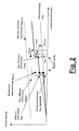
- FIG. 2 shows the calculated course of the amount of ash deposited in the diesel particle filter as a function of the "running distance” or "mileage” of the engine.
- the adjusted amount of ash (see Fig. 2) can be calculated according to the following formula.
- ⁇ corr A * ⁇ is new + B * ⁇ korralt + C * ⁇ should / A + B + C ,
- the functions A, B, C can be, for example, constant or functions of mileage.
- the determined amount of ash ⁇ corr is stored when the vehicle is parked in a memory of the engine control and read at the next engine start as ⁇ korralt . If the difference between ⁇ ACTnew and the originally estimated amount to the value exceeds ⁇ difftotmax ⁇ , so the comparison is "frozen" and it is assumed that an error or a malfunction.
Landscapes
- Engineering & Computer Science (AREA)
- Chemical & Material Sciences (AREA)
- Combustion & Propulsion (AREA)
- Mechanical Engineering (AREA)
- General Engineering & Computer Science (AREA)
- Processes For Solid Components From Exhaust (AREA)
- Filtering Of Dispersed Particles In Gases (AREA)
Abstract
Claims (10)
- Procédé pour la régénération d'un filtre à particules (3) d'un système de gaz d'échappement, obstrué par des cendres et de la suie,
selon lequel
on diminue de temps à autre le degré d'obstruction du filtre à particules (3) provoqué par la suie déposée par combustion d'une grande partie de celle-ci, et
on choisit des paramètres de combustion pour une opération de régénération en fonction du degré d'obstruction provoqué par la quantité de cendres déposée dans le filtre à suie,
caractérisé en ce qu'
on détermine le degré d'obstruction, provoqué par la quantité de cendres déposée, par la mesure d'une grandeur de pression des gaz d'échappement, en amont du filtre à suie. - Procédé selon la revendication 1,
caractérisé en ce qu'
on détermine la quantité de cendres déposée ou le degré d'obstruction ainsi provoqué sur la base d'une grandeur de pression des gaz d'échappement, en amont du filtre à particules (3) immédiatement après la fin de l'opération de régénération. - Procédé selon la revendication 1 ou 2,
caractérisé en ce que
la grandeur de pression des gaz d'échappement est une pression des gaz d'échappement rapportée à leur débit volumique. - Procédé selon l'une des revendications 1 à 3,
caractérisé en ce qu'
on détermine la quantité de suie déposée ou le degré d'obstruction ainsi provoqué, notamment par l'addition pondérée des grandeurs suivantes :- une quantité de suie considérée finalement comme valable (αkorralt) ou un degré d'obstruction considéré finalement comme valable ;- une quantité de cendres estimée après la dernière régénération (αistneu), déterminée à partir de la grandeur de pression des gaz d'échappement mesurée immédiatement après la dernière régénération ;- une valeur de consigne prédéterminée de la quantité de cendres (αsoll) dépendant de la durée de fonctionnement. - Procédé selon la revendication 4,
caractérisé en ce qu'
on détermine la quantité de cendres déposée (αkorr) par la formule :
- Procédé selon la revendication 5,
caractérisé en ce que
A, B et C sont des constantes. - Procédé selon la revendication 5,
caractérisé en ce que
A, B et C sont des fonctions de la durée de fonctionnement. - Procédé selon l'une des revendications 4 à 7,
caractérisé en ce que
la quantité de cendres considérée finalement comme valable (αkorralt) est posée égale à la valeur de consigne correspondante (αsoll) avant l'exécution de la première régénération du filtre à particules (3). - Procédé selon l'une des revendications 1 à 8,
caractérisé en ce qu'
on choisit la durée de la régénération en fonction de la température des gaz d'échappement régnant pendant la régénération et du degré d'obstruction du filtre à particules (3) provoqué par les cendres. - Procédé selon l'une des revendications 1 à 9,
caractérisé en ce qu'
on choisit la durée de la régénération de façon à brûler au moins 90 % de la suie déposée dans le filtre à particules (3).
Applications Claiming Priority (3)
| Application Number | Priority Date | Filing Date | Title |
|---|---|---|---|
| DE10223427 | 2002-05-25 | ||
| DE10223427A DE10223427A1 (de) | 2002-05-25 | 2002-05-25 | Verfahren zur Regenerierung eines verstopften Partikelfilters |
| PCT/EP2003/003641 WO2003100227A1 (fr) | 2002-05-25 | 2003-04-08 | Procede pour la regeneration d'un filtre a particules bouche |
Publications (2)
| Publication Number | Publication Date |
|---|---|
| EP1507963A1 EP1507963A1 (fr) | 2005-02-23 |
| EP1507963B1 true EP1507963B1 (fr) | 2007-07-11 |
Family
ID=29557314
Family Applications (1)
| Application Number | Title | Priority Date | Filing Date |
|---|---|---|---|
| EP03722419A Expired - Lifetime EP1507963B1 (fr) | 2002-05-25 | 2003-04-08 | Procede pour la regeneration d'un filtre a particules bouche |
Country Status (4)
| Country | Link |
|---|---|
| EP (1) | EP1507963B1 (fr) |
| JP (1) | JP4399355B2 (fr) |
| DE (2) | DE10223427A1 (fr) |
| WO (1) | WO2003100227A1 (fr) |
Families Citing this family (18)
| Publication number | Priority date | Publication date | Assignee | Title |
|---|---|---|---|---|
| JP3869333B2 (ja) * | 2002-08-12 | 2007-01-17 | ボッシュ株式会社 | 排気ガス浄化装置 |
| JP3801135B2 (ja) * | 2003-01-08 | 2006-07-26 | 日産自動車株式会社 | エンジンの排気ガス浄化装置 |
| DE10359395A1 (de) | 2003-12-18 | 2005-07-21 | Daimlerchrysler Ag | Verfahren zum Betreiben eines Partikelfilters im Abgasstrang einer Brennkraftmaschine eines Kraftfahrzeugs |
| JP4103813B2 (ja) * | 2004-02-02 | 2008-06-18 | トヨタ自動車株式会社 | 内燃機関の排気浄化装置 |
| DE102004055605B4 (de) * | 2004-11-18 | 2015-10-29 | Volkswagen Ag | Verfahren zum Bestimmen einer Rußbeladung eines Partikelfilters |
| JP4572762B2 (ja) * | 2005-07-08 | 2010-11-04 | 日産自動車株式会社 | エンジンの排気浄化装置 |
| US7607295B2 (en) | 2005-07-07 | 2009-10-27 | Nissan Motor Co., Ltd. | Particulate accumulation amount estimating system |
| JP4534969B2 (ja) | 2005-11-25 | 2010-09-01 | 株式会社デンソー | 内燃機関用排気浄化装置 |
| DE102006012351B4 (de) | 2006-03-17 | 2023-06-15 | Mercedes-Benz Group AG | Verfahren zum Betreiben eines im Abgasstrang einer Brennkraftmaschine angeordneten regenerierbaren Partikelfilters |
| KR100969370B1 (ko) * | 2007-12-14 | 2010-07-09 | 현대자동차주식회사 | 매연여과장치의 유효체적 계산 방법 |
| DE102009060509A1 (de) | 2009-12-23 | 2011-06-30 | MTU Friedrichshafen GmbH, 88045 | Verfahren zur Regeneration eines Partikelfilters |
| SE535154C2 (sv) * | 2010-08-31 | 2012-05-02 | Scania Cv Ab | Förfarande och system för avgasrening |
| SE537798C2 (sv) * | 2011-04-20 | 2015-10-20 | Scania Cv Ab | Upphängningssystem för ljuddämpningsanordning vid ett fordon |
| FR2976319A1 (fr) * | 2011-06-10 | 2012-12-14 | Peugeot Citroen Automobiles Sa | Procede de gestion de la regeneration d'un filtre a particules |
| DE102017205390A1 (de) | 2017-03-30 | 2018-07-12 | Audi Ag | Verfahren zum Betreiben eines Partikelfilters |
| DE102017208639A1 (de) | 2017-05-22 | 2018-06-07 | Audi Ag | Verfahren zur Reaktivierung von Abgaskatalysatoren |
| DE102018010415B3 (de) | 2018-05-09 | 2021-11-04 | Bayerische Motoren Werke Aktiengesellschaft | Ermitteln einer Aschebeladung eines Partikelfilters für einen Verbrennungsmotor |
| DE102018207227B4 (de) | 2018-05-09 | 2021-10-07 | Bayerische Motoren Werke Aktiengesellschaft | Ermitteln einer Aschebeladung eines Partikelfilters für einen Verbrennungsmotor |
Citations (1)
| Publication number | Priority date | Publication date | Assignee | Title |
|---|---|---|---|---|
| US5319930A (en) * | 1989-12-27 | 1994-06-14 | Nissan Motor Co., Ltd. | Exhaust gas purifying device for an internal combustion engine |
Family Cites Families (4)
| Publication number | Priority date | Publication date | Assignee | Title |
|---|---|---|---|---|
| EP0349788B1 (fr) * | 1988-06-09 | 1992-12-30 | IVECO FIAT S.p.A. | Méthode et dispositif pour la commande de la régénération d'au moins un filtre à particules installé dans un moteur diesel |
| JPH07310524A (ja) * | 1994-05-13 | 1995-11-28 | Nippondenso Co Ltd | ディーゼルパティキュレート捕集量検出装置 |
| DE60002652T2 (de) * | 1999-11-26 | 2004-04-01 | Renault S.A.S. | Regelungverfahren eines Partikelfilters und Regelungsverfahren einer Brennkraftmaschine |
| JP4022714B2 (ja) * | 2001-06-25 | 2007-12-19 | 三菱ふそうトラック・バス株式会社 | 内燃機関の排気浄化装置 |
-
2002
- 2002-05-25 DE DE10223427A patent/DE10223427A1/de not_active Withdrawn
-
2003
- 2003-04-08 JP JP2004507657A patent/JP4399355B2/ja not_active Expired - Lifetime
- 2003-04-08 EP EP03722419A patent/EP1507963B1/fr not_active Expired - Lifetime
- 2003-04-08 DE DE50307655T patent/DE50307655D1/de not_active Expired - Lifetime
- 2003-04-08 WO PCT/EP2003/003641 patent/WO2003100227A1/fr not_active Ceased
Patent Citations (1)
| Publication number | Priority date | Publication date | Assignee | Title |
|---|---|---|---|---|
| US5319930A (en) * | 1989-12-27 | 1994-06-14 | Nissan Motor Co., Ltd. | Exhaust gas purifying device for an internal combustion engine |
Also Published As
| Publication number | Publication date |
|---|---|
| JP2005527735A (ja) | 2005-09-15 |
| JP4399355B2 (ja) | 2010-01-13 |
| EP1507963A1 (fr) | 2005-02-23 |
| DE50307655D1 (de) | 2007-08-23 |
| WO2003100227A1 (fr) | 2003-12-04 |
| DE10223427A1 (de) | 2003-12-18 |
Similar Documents
| Publication | Publication Date | Title |
|---|---|---|
| EP1507963B1 (fr) | Procede pour la regeneration d'un filtre a particules bouche | |
| DE602004008862T2 (de) | Verfahren zur Aktivierung der Regeneration eines Partikelfilters auf Basis von der Schätzung des in dem Partikelfilter angesammelten Partikelmenge | |
| DE602004001524T2 (de) | Vorrichtung und Verfahren zur Abgasreinigung | |
| EP1336039B1 (fr) | Procede et dispositif de commande d'un systeme de retraitement des gaz d'echappement | |
| EP1992935B1 (fr) | Procédé de fonctionnement d'un capteur à particules disposé en aval après un filtre à particules et dispositif d'exécution du procedée | |
| EP2326809B1 (fr) | Procédé d'utilisation d'un dispositif de traitement des gaz d'échappement comportant un catalyseur à réduction catalytique sélective et un composant de traitement des gaz d'échappement à activité catalytique d'oxydation monté en amont | |
| DE10154261B4 (de) | Verfahren zur Bestimmung der Beladung eines Teilchenfilters im Abgasweg eines Motors | |
| DE602004001154T2 (de) | Abgasreinigungsvorrichtung für Brennkraftmaschinen | |
| DE102007059523B4 (de) | Verfahren und Vorrichtung zur Diagnose eines Partikelfilters | |
| DE602004001471T2 (de) | Motorabgasreinigungsvorrichtung | |
| DE102007000474B4 (de) | Abgasreinigungsvorrichtung | |
| DE112016000123B4 (de) | Abgasreinigungssystem und Abgasreinigungsverfahren | |
| DE112007003140T5 (de) | Sensorabnormalitätsdetektionsvorrichtung und Sensorabnormalitätsdetektionsverfahren | |
| DE102010027975A1 (de) | Verfahren und Vorrichtung zur Eigendiagnose einer Abgassonde | |
| DE102014205685B4 (de) | Verfahren zum Betreiben einer Brennkraftmaschine, Steuergerät und Brennkraftmaschine | |
| EP1108862A2 (fr) | Procédé et dispositif pour diminuer les constituants nocifs de gaz d'échappement dans un moteur à combustion | |
| DE102007000001A1 (de) | Verfahren zur Erfassung einer übermäßigen Verbrennung | |
| DE102009058698B4 (de) | Ermittlung der Effizienz eines Partikelfilters durch Messung des Druckabfalles an einem zusätzlichen Partikelfilter | |
| DE102008014509B4 (de) | Verfahren und Vorrichtung zum Ermitteln einer Masse an Ruß in einem Partikelfilter | |
| DE102018104258A1 (de) | Technik zur Kraftstoffbestimmung | |
| DE102009001538B4 (de) | Verfahren zum Betreiben eines Partikelfilters sowie Partikelfilter | |
| DE102005000978B4 (de) | Vorrichtung zur Steuerung des Schadstoffausstoßes eines selbstzündenden Verbrennungsmotors | |
| EP1180210B2 (fr) | Procede et dispositif pour commander un moteur a combustion interne equipe d'un systeme de retraitement des gaz d'echappement | |
| EP1170473B1 (fr) | Mèthode de commande d'un moteur à combustion | |
| DE10233945B4 (de) | Verfahren zur Reinigung eines Partikelfilters |
Legal Events
| Date | Code | Title | Description |
|---|---|---|---|
| PUAI | Public reference made under article 153(3) epc to a published international application that has entered the european phase |
Free format text: ORIGINAL CODE: 0009012 |
|
| 17P | Request for examination filed |
Effective date: 20031205 |
|
| AK | Designated contracting states |
Kind code of ref document: A1 Designated state(s): AT BE BG CH CY CZ DE DK EE ES FI FR GB GR HU IE IT LI LU MC NL PT RO SE SI SK TR |
|
| 17Q | First examination report despatched |
Effective date: 20050610 |
|
| RBV | Designated contracting states (corrected) |
Designated state(s): DE FR GB IT |
|
| GRAP | Despatch of communication of intention to grant a patent |
Free format text: ORIGINAL CODE: EPIDOSNIGR1 |
|
| GRAS | Grant fee paid |
Free format text: ORIGINAL CODE: EPIDOSNIGR3 |
|
| GRAA | (expected) grant |
Free format text: ORIGINAL CODE: 0009210 |
|
| AK | Designated contracting states |
Kind code of ref document: B1 Designated state(s): DE FR GB IT |
|
| REG | Reference to a national code |
Ref country code: GB Ref legal event code: FG4D Free format text: NOT ENGLISH |
|
| GBT | Gb: translation of ep patent filed (gb section 77(6)(a)/1977) |
Effective date: 20070711 |
|
| REF | Corresponds to: |
Ref document number: 50307655 Country of ref document: DE Date of ref document: 20070823 Kind code of ref document: P |
|
| ET | Fr: translation filed | ||
| PLBE | No opposition filed within time limit |
Free format text: ORIGINAL CODE: 0009261 |
|
| STAA | Information on the status of an ep patent application or granted ep patent |
Free format text: STATUS: NO OPPOSITION FILED WITHIN TIME LIMIT |
|
| 26N | No opposition filed |
Effective date: 20080414 |
|
| REG | Reference to a national code |
Ref country code: FR Ref legal event code: PLFP Year of fee payment: 14 |
|
| REG | Reference to a national code |
Ref country code: FR Ref legal event code: PLFP Year of fee payment: 15 |
|
| REG | Reference to a national code |
Ref country code: FR Ref legal event code: PLFP Year of fee payment: 16 |
|
| PGFP | Annual fee paid to national office [announced via postgrant information from national office to epo] |
Ref country code: IT Payment date: 20220429 Year of fee payment: 20 Ref country code: GB Payment date: 20220425 Year of fee payment: 20 Ref country code: FR Payment date: 20220420 Year of fee payment: 20 Ref country code: DE Payment date: 20220421 Year of fee payment: 20 |
|
| REG | Reference to a national code |
Ref country code: DE Ref legal event code: R071 Ref document number: 50307655 Country of ref document: DE |
|
| REG | Reference to a national code |
Ref country code: GB Ref legal event code: PE20 Expiry date: 20230407 |
|
| P01 | Opt-out of the competence of the unified patent court (upc) registered |
Effective date: 20230503 |
|
| PG25 | Lapsed in a contracting state [announced via postgrant information from national office to epo] |
Ref country code: GB Free format text: LAPSE BECAUSE OF EXPIRATION OF PROTECTION Effective date: 20230407 |