EP1507997B1 - Vorrichtung zur kompensation von längenänderungen in einem rohrsystem - Google Patents
Vorrichtung zur kompensation von längenänderungen in einem rohrsystem Download PDFInfo
- Publication number
- EP1507997B1 EP1507997B1 EP03740138A EP03740138A EP1507997B1 EP 1507997 B1 EP1507997 B1 EP 1507997B1 EP 03740138 A EP03740138 A EP 03740138A EP 03740138 A EP03740138 A EP 03740138A EP 1507997 B1 EP1507997 B1 EP 1507997B1
- Authority
- EP
- European Patent Office
- Prior art keywords
- sleeve
- pipe
- pipe element
- torsion
- tubular element
- Prior art date
- Legal status (The legal status is an assumption and is not a legal conclusion. Google has not performed a legal analysis and makes no representation as to the accuracy of the status listed.)
- Expired - Lifetime
Links
- 230000006835 compression Effects 0.000 claims description 6
- 238000007906 compression Methods 0.000 claims description 6
- 238000009434 installation Methods 0.000 description 9
- 238000007639 printing Methods 0.000 description 7
- 230000036316 preload Effects 0.000 description 5
- 230000008602 contraction Effects 0.000 description 4
- 230000002349 favourable effect Effects 0.000 description 4
- 239000004033 plastic Substances 0.000 description 4
- 238000006073 displacement reaction Methods 0.000 description 3
- 230000033001 locomotion Effects 0.000 description 3
- 239000002184 metal Substances 0.000 description 3
- 238000000418 atomic force spectrum Methods 0.000 description 2
- 230000005540 biological transmission Effects 0.000 description 2
- 238000010276 construction Methods 0.000 description 2
- 238000010586 diagram Methods 0.000 description 2
- 229920001971 elastomer Polymers 0.000 description 2
- 239000000806 elastomer Substances 0.000 description 2
- 239000000463 material Substances 0.000 description 2
- 230000002093 peripheral effect Effects 0.000 description 2
- 239000000243 solution Substances 0.000 description 2
- XLYOFNOQVPJJNP-UHFFFAOYSA-N water Substances O XLYOFNOQVPJJNP-UHFFFAOYSA-N 0.000 description 2
- 238000003466 welding Methods 0.000 description 2
- 230000002411 adverse Effects 0.000 description 1
- 238000005452 bending Methods 0.000 description 1
- 230000001143 conditioned effect Effects 0.000 description 1
- 230000001419 dependent effect Effects 0.000 description 1
- 230000000694 effects Effects 0.000 description 1
- 238000005516 engineering process Methods 0.000 description 1
- 210000003746 feather Anatomy 0.000 description 1
- 238000010438 heat treatment Methods 0.000 description 1
- 238000002347 injection Methods 0.000 description 1
- 239000007924 injection Substances 0.000 description 1
- 238000001746 injection moulding Methods 0.000 description 1
- 238000004519 manufacturing process Methods 0.000 description 1
- 238000004806 packaging method and process Methods 0.000 description 1
- 229920000642 polymer Polymers 0.000 description 1
- 230000002028 premature Effects 0.000 description 1
- 230000002441 reversible effect Effects 0.000 description 1
- 238000005096 rolling process Methods 0.000 description 1
- 238000004904 shortening Methods 0.000 description 1
- 238000003892 spreading Methods 0.000 description 1
- 230000003068 static effect Effects 0.000 description 1
- 229920002725 thermoplastic elastomer Polymers 0.000 description 1
Images


Classifications
-
- F—MECHANICAL ENGINEERING; LIGHTING; HEATING; WEAPONS; BLASTING
- F16—ENGINEERING ELEMENTS AND UNITS; GENERAL MEASURES FOR PRODUCING AND MAINTAINING EFFECTIVE FUNCTIONING OF MACHINES OR INSTALLATIONS; THERMAL INSULATION IN GENERAL
- F16L—PIPES; JOINTS OR FITTINGS FOR PIPES; SUPPORTS FOR PIPES, CABLES OR PROTECTIVE TUBING; MEANS FOR THERMAL INSULATION IN GENERAL
- F16L51/00—Expansion-compensation arrangements for pipe-lines
Definitions
- the invention relates to a device for Compensation of changes in length in a pipe system according to the preamble of the main claim.
- a device for Compensation of changes in length in a pipe system is known from GB-A-1 386 774.
- Typical applications of the present invention are Hot water and cold water pipes in buildings as well Drain lines.
- the invention has for its object to provide a device for Compensation of changes in length in a pipe system too create which in a simple structure and easier, trouble-free operation, the disadvantages of the prior Technology avoids.
- the device a comprises elastic tube member which is biased to train and secured by means of a detachable securing device is, as well as with one of the bias of the tubular element counteracting printing device.
- the principle underlying the invention thus exists it is to bias an elastic tube element to train. This transmits, if it is installed in a pipe system, thus the tensile prestressing on the entire pipe system. at a heating of the elastic tubular element expands this out, whereby the tension is lower. Since the Expansion or contraction of the pipe element in dependence of the dimensioning and the selected materials nonlinear behaves, according to the invention, the printing device provided, which to some extent the train bias of the Tube element compensated and thus a desired Pressure curve of the overall device ensures.
- the inventively provided releasable safety device allows the device of the invention in a Install pipe system. After installation in the pipe system is solved the safety device, so that the bias of the elastic tubular element can be effective. hereby the installation of the device is considerably simplified In particular, it can also be used by less experienced professionals be installed without these special measures Ensuring the appropriate preload must meet.
- the device according to the invention is thus with undissolved Securing device in a first, stationary Functional position provided. This functional position is provided for the installation of the device. To completed installation and release of the safety device results is a dynamic, second functional position in which the device according to the invention changes in length of a Pipe system, which are thermally conditioned in particular, can compensate.
- the device according to the invention also can be used in pipe systems, for other reasons Length changes are subject. There is no thermal expansion or contraction of the tubular element itself required, but rather in connection with the entire pipe system in which the device is installed.
- the bias of the tubular element to train and the pressure bias of the printing device in each case so are chosen that in the sum of a substantially results in a linear spring force curve in the device. Consequently For example, it is possible to have a consistent one Tensile stress of 200 N in a pipe system by means of To realize device according to the invention.
- inventive device by the combination of train bias the elastic tube member and the counteracting Printing device can be built very short and compact.
- the printing device can preferably be formed by at least one spring.
- a Torsion device for torsion of the tubular element itself is formed.
- no additional Spring elements required, but the elasticity of the Pipe element itself for the counteracting printing device be used.
- the Torsions worn at least one of the tubular element fastened driver comprises, which is at least a cam track of a link element is engaged.
- the pipe element is biased to torsion.
- the inventive provided safety device can preferably in the form of a device at least be formed partially enclosing locking sleeve.
- This locking sleeve can axially and / or in the circumferential direction be solvable. After installation of the device can thus the Locking sleeve can be moved or twisted (or be solved accordingly). This is a special simple operation of the device according to the invention ensured by untrained Installation craftsmen can be carried out safely.
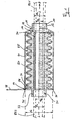
- Fig. 1 in section Device comprises a first sleeve 10, which is substantially is cylindrical, with a cylindrical shell 12, which at one end (in the figure left) widened inwardly, forming a wall 14, which has an opening in the center, concentric with the Longitudinal axis L of the device runs and a diameter d2 having.
- the inner diameter of the cylindrical shell 12th is indicated by d1.
- the jacket 12 has circumferentially in section triangular widening (bevel 16) with a Undercut 18 on the wall 14 facing side.
- a tubular element 20 includes a Elastomer whose inner diameter corresponds to about d2 and whose outer diameter is approximately equal to d1.
- a second sleeve 30 At the opposite end of the tubular element 20 with a second sleeve 30 connected.
- the construction of the sleeve 30 essentially corresponds to the sleeve 10. This applies in particular for the cylinder jacket 32 with the Inner diameter d1 and a wall 34 with an opening of the Diameter d2, wherein the arrangement of the sleeve 30th mirror image of the sleeve 10 is.
- Fig. 1 reveals that the sleeve 30 no Ramp has, the wall 34 but circumferentially (Radial) projects beyond the jacket 32, wherein the Outer diameter of the wall 34 is indicated by d3.
- the sleeves 10, 30 with the pipe element arranged therebetween 20 form a structural unit, even if the sleeves 10, 30 made of metal and the tube member 20 made of an elastomer are.
- Device For further packaging of the invention Device is this example with the sleeve 30th clamped. Thereafter, the first sleeve 10 by means of a Spreading tool extending from the inside against the cylindrical Clad 12 digs, pulled away from the sleeve 30 (Arrow Z), so that the tube member 20 under tension device.
- the tubular element 20 has the higher preload.
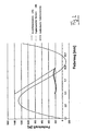
- the disc springs 40 are above an upper Vertex of their spring characteristic biased and located in the area of a declining force course of their Spring characteristic. That is, with increasing spring travel takes the Power off. It remains below the spring characteristic of the Tube element 20. Due to this combination of springs it comes to an approximately constant course of force over the to be included way, as the diagram of FIG. 2 can be seen is. This is the force-displacement curve of each one Spring element 20, 40 and their combination (wavy line at about 200 N +/- 25 N).
- the sleeve 50 prevents the installation of the invention Device premature contraction of the tubular element 20th (or the sleeves 10, 30) and allows a tension-free Installation in a piping system, in the corresponding first and second pipe pieces RS 1, RS 2 with the sleeves 10, 30 get connected. This can be done, for example, by welding respectively.
- the length of the displacement of the sleeve 50 depends on the degree of Bias of the tube member 20 and the plate springs 40 and their vote on each other.
- FIGS. 3 to 7 show a second embodiment of the Invention. They are the same parts with the same Reference numbers provided.
- the second embodiment is an elastic Pipe element 20 with a first sleeve 10 and a second Muff 30 connected.
- the connection of the tubular element 20 can for example, by injection molding of polymer, the Sockets 10 and 30 can be made of plastic or metal be prepared.
- drivers 61, 62 are fastened to the tubular element 20. These can be designed in the form of rolls that around corresponding, not provided in detail with reference numerals Pins are rotatable, which in turn on the tubular element 20th are attached.
- two drivers 61, 62 arranged side by side. To the Scope are three such arrangements of drivers 61, 62nd intended.
- FIG. 5 shows a state in which only one link element 65 is mounted. This supports against the second sleeve 30 and is rotatably to this. It can be seen that the drivers 61, 62 (rollers) on an axial portion of the cam track 63 rest. This represents in the embodiment shown the Initial state.
- the link element 65 which sleeve-like or tubular is formed, has a radial to the tubular element 20 Distance, so that a second link element 66 between the tubular element 20 and the link element 65 telescopic can be inserted (see Fig. 3).
- the second link element 66 is constructed symmetrically. the two Slotted elements 65 and 66 are thus in the axial direction mutually displaceable. This sliding movement is through caused a shortening of the tubular element 20.
- FIGS. 6 and 7 is the central region of the tubular element 20 of a Secured device 50 encompassed, which is tubular is.
- the safety device 50 is supported in the static, secured state against a nose 67 of the second Sliding element 66 from and lies with a thickened area 68 against the free end of the first link element 65 at.
- the two link elements 65, 66 thus can not be in Move the axial direction telescopically to each other.
- the Embodiment are both the nose 67 and the Thickened area 68 each not over the entire circumference designed so that a rotation of the securing device 50 leads to a corresponding release, causing the dynamic state of installation of the device according to the invention is achieved. From the illustration of FIG.
- the second embodiment thus essentially constitutes a non-uniform geared transmission, namely a Three-part cam mechanism with forced operation, whereby the inner part (tube member 20) in a simple manner as a spring acts and the roles of the drivers 61, 62 on the Roll cam tracks 63, 64.
- the power transmission achieved with the goal of a uniform bias.
- the individual components can either completely made of plastic. There are but also mixed construction methods made of plastic and metal possible.
- the tubular element 20 according to the invention can be used in applications reinforced or reinforced to a large internal pressure to avoid radial expansion. They are also mechanical Support elements used, for example in the form of discs, which sit on the tubular element 20 and, for example lie between the disc springs 40.
- the tubular element 20 may be made of a thermoplastic elastomer be formed, with a reversible deformability and a high tensile strength are advantageous.
- the Securing device 50 also securable in other ways be, for example, by removable locking pins or Like.
- connection of the tubular element 20 with the sleeves 10, 30 can made in one piece or otherwise. It is possible the To connect parts by welding or injection.
Landscapes
- Engineering & Computer Science (AREA)
- General Engineering & Computer Science (AREA)
- Mechanical Engineering (AREA)
- Springs (AREA)
- Quick-Acting Or Multi-Walled Pipe Joints (AREA)
- Mutual Connection Of Rods And Tubes (AREA)
- Actuator (AREA)
Description
- Fig. 1
- eine vereinfachte Schnittansicht eines ersten Ausführungsbeispiels der erfindungsgemäßen Vorrichtung,
- Fig. 2
- ein Kraft-Weg-Diagramm zur Erläuterung der Wirkungsweise der erfindungsgemäßen Vorrichtung,
- Fig. 3
- eine perspektivische, vereinfachte Darstellung eines weiteren Ausführungsbeispiels der erfindungsgemäßen Vorrichtung in teilweise montiertem Zustand,
- Fig. 4
- eine Darstellung des mit dem Ausführungsbeispiel der Fig. 3 verwendeten Rohrelements,
- Fig. 5
- eine Darstellung im teilmontierten Zustand,
- Fig. 6
- eine perspektivische Darstellung des zweiten Ausführungsbeispiels, und
- Fig. 7
- eine Längs-Schnittansicht der Anordnung gemäß Fig. 6.
- 10
- Erste Muffe
- 12
- Mantel
- 14
- Wand
- 16
- Auflaufschräge
- 18
- Hinterschnitt
- 20
- Rohrelement
- 30
- Zweite Muffe
- 32
- Mantel
- 34
- Wand
- 36
- Stützelement
- 38
- Ring
- 40
- Feder
- 45
- Ringraum
- 50
- Sicherungseinrichtung
- 52
- Stirnfläche
- 54
- Innerer Abschnitt
- 61
- Mitnehmer
- 62
- Mitnehmer
- 63
- Kurvenbahn
- 64
- Kurvenbahn
- 65
- Kulissenelement
- 66
- Kulissenelement
- 67
- Nase
- 68
- Verdickter Bereich
Claims (10)
- Vorrichtung zur Kompensation von Längenänderungen in einem Rohrsystem, mit einem elastischen Rohrelement (20), welches auf Zug vorgespannt und mittels einer lösbaren Sicherungseinrichtung (50) gesichert ist, gekennzeichnet durch eine der Vorspannung des Rohrelements (20) gegenwirkende Druckeinrichtung.
- Vorrichtung nach Anspruch 1, dadurch gekennzeichnet, dass die Vorspannung des Rohrelements (20) auf Zug sowie die Druck-Vorspannung der Druckeinrichtung jeweils so gewählt sind, dass sich in der Summe ein im Wesentlichen linearer Federkraftverlauf in der Vorrichtung ergibt.
- Vorrichtung nach Anspruch 1 oder 2, dadurch gekennzeichnet, dass die Druckeinrichtung durch zumindest eine Feder (40) gebildet wird.
- Vorrichtung nach einem der Ansprüche 1 bis 3, dadurch gekennzeichnet, dass die Druckeinrichtung durch eine Torsionseinrichtung zur Torsion des Rohrelements (20) gebildet wird.
- Vorrichtung nach Anspruch 4, dadurch gekennzeichnet, dass die Torsionseinrichtung zumindest einen an dem Rohrelement (20) befestigten Mitnehmer (61, 62) umfasst, welcher sich mit zumindest einer Kurvenbahn (63, 64) eines Kulissenelements (65, 66) im Eingriff befindet.
- Vorrichtung nach Anspruch 5, dadurch gekennzeichnet, dass das Kulissenelement (65, 66) in Form zweier zueinander teleskopischer, das Rohrelement (20) umgebender Hülsen (65, 66) ausgebildet ist.
- Vorrichtung nach Anspruch 6, dadurch gekennzeichnet, dass die Hülsen (65, 66) drehfest an der Vorrichtung gelagert sind.
- Vorrichtung nach einem der Ansprüche 4 bis 7, dadurch gekennzeichnet, dass das Rohrelement (20) auf Torsion vorgespannt ist.
- Vorrichtung nach einem der Ansprüche 1 bis 8, dadurch gekennzeichnet, dass die Sicherungseinrichtung in Form einer die Vorrichtung zumindest teilweise umschließenden Sicherungshülse (50) ausgebildet ist.
- Vorrichtung nach Anspruch 9, dadurch gekennzeichnet, dass die Sicherungshülse (50) axial und/oder in Umfangsrichtung lösbar ist.
Priority Applications (2)
| Application Number | Priority Date | Filing Date | Title |
|---|---|---|---|
| AT03740138T ATE306043T1 (de) | 2002-05-29 | 2003-05-15 | Vorrichtung zur kompensation von längenänderungen in einem rohrsystem |
| SI200330126T SI1507997T1 (sl) | 2002-05-29 | 2003-05-15 | Naprava za kompenzacijo sprememb dolzin v cevnem sistemu |
Applications Claiming Priority (3)
| Application Number | Priority Date | Filing Date | Title |
|---|---|---|---|
| AT34302U | 2002-05-29 | ||
| AT0034302U AT6113U1 (de) | 2002-05-29 | 2002-05-29 | Einrichtung zur kompensation von längenänderungen entlang von rohrleitungssystemen |
| PCT/EP2003/005122 WO2003100311A2 (de) | 2002-05-29 | 2003-05-15 | Vorrichtung zur kompensation von längenänderungen in einem rohrsystem |
Publications (2)
| Publication Number | Publication Date |
|---|---|
| EP1507997A2 EP1507997A2 (de) | 2005-02-23 |
| EP1507997B1 true EP1507997B1 (de) | 2005-10-05 |
Family
ID=3488067
Family Applications (1)
| Application Number | Title | Priority Date | Filing Date |
|---|---|---|---|
| EP03740138A Expired - Lifetime EP1507997B1 (de) | 2002-05-29 | 2003-05-15 | Vorrichtung zur kompensation von längenänderungen in einem rohrsystem |
Country Status (7)
| Country | Link |
|---|---|
| EP (1) | EP1507997B1 (de) |
| AT (1) | AT6113U1 (de) |
| AU (1) | AU2003273148A1 (de) |
| DE (1) | DE50301319D1 (de) |
| DK (1) | DK1507997T3 (de) |
| ES (1) | ES2250901T3 (de) |
| WO (1) | WO2003100311A2 (de) |
Families Citing this family (4)
| Publication number | Priority date | Publication date | Assignee | Title |
|---|---|---|---|---|
| CA2855326A1 (en) * | 2014-06-26 | 2015-12-26 | G.B.D. Corp. | Method of installing an expansion compensator |
| CN108506639A (zh) * | 2018-05-23 | 2018-09-07 | 海宁市晟达消防设备有限公司 | 防膨胀不锈钢网管 |
| CN114893636A (zh) * | 2022-04-07 | 2022-08-12 | 中海油能源发展股份有限公司 | 一种海洋移动注热系统高温高压补偿管线装置 |
| CN118423536B (zh) * | 2024-07-05 | 2024-09-10 | 泰州市星海管业有限公司 | 一种抗扭曲的膨胀节装置 |
Family Cites Families (2)
| Publication number | Priority date | Publication date | Assignee | Title |
|---|---|---|---|---|
| GB1386774A (en) * | 1971-02-08 | 1975-03-12 | Rasmussen As E | Axial pipe compensators |
| DE4417407C1 (de) * | 1994-05-18 | 1995-11-30 | Burgmann Dichtungswerk Feodor | Flexible Verbindungsanordnung für zwei Rohrteile, insbesondere bei Abgasanlagen von Kraftfahrzeugen |
-
2002
- 2002-05-29 AT AT0034302U patent/AT6113U1/de not_active IP Right Cessation
-
2003
- 2003-05-15 AU AU2003273148A patent/AU2003273148A1/en not_active Abandoned
- 2003-05-15 ES ES03740138T patent/ES2250901T3/es not_active Expired - Lifetime
- 2003-05-15 WO PCT/EP2003/005122 patent/WO2003100311A2/de not_active Ceased
- 2003-05-15 EP EP03740138A patent/EP1507997B1/de not_active Expired - Lifetime
- 2003-05-15 DE DE50301319T patent/DE50301319D1/de not_active Expired - Fee Related
- 2003-05-15 DK DK03740138T patent/DK1507997T3/da active
Also Published As
| Publication number | Publication date |
|---|---|
| AU2003273148A1 (en) | 2003-12-12 |
| ES2250901T3 (es) | 2006-04-16 |
| DE50301319D1 (de) | 2006-02-16 |
| DK1507997T3 (da) | 2006-02-20 |
| EP1507997A2 (de) | 2005-02-23 |
| AT6113U1 (de) | 2003-04-25 |
| WO2003100311A3 (de) | 2004-01-15 |
| WO2003100311A2 (de) | 2003-12-04 |
Similar Documents
| Publication | Publication Date | Title |
|---|---|---|
| DE3907294A1 (de) | Universalkugelverbindung | |
| EP1234136A1 (de) | Vorrichtung zur herstellung einer rohrkupplung | |
| EP3409556A1 (de) | Verbundsystem, feuerschutzschrank und transportmittel aufweisend einen feuerschutzschrank | |
| DE19619839C1 (de) | Hydraulikkupplung | |
| DE2620334A1 (de) | Selbsttaetig gefuehrter axialer rohrkompensator | |
| DE2621044B2 (de) | Rohrverbindung | |
| EP0913612A1 (de) | Verfahren zum Verbinden eines Rohres mit einer Rohrkupplung, Verbindung zwischen einem Rohr und einer Rohrkupplung sowie Rohrkupplung hierfür | |
| EP0816738B1 (de) | Entkopplungselement für Schwingungen in Rohrleitungen | |
| DE3230932C2 (de) | Kupplung | |
| EP0918968B1 (de) | Kupplungsvorrichtung für die herstellung einer rohrverbindung | |
| DE3935960C2 (de) | Einrichtung zur abdichtenden Überbrückung eines Spaltes zwischen zwei in drei Raumrichtungen verschiebbaren Bauteilen | |
| DE202011105923U1 (de) | Rohrleitungsanordnung und Verbindung für eine solche | |
| DE102018205891B3 (de) | Durch Fluidbeaufschlagung aktivierbare Betätigungseinrichtung mit Rastmechanismus | |
| DE19543092A1 (de) | Verfahren zur Herstellung einer Rohrverbindung sowie Kupplungsvorrichtung für die Herstellung einer Rohrverbindung | |
| EP1218659B1 (de) | Vorrichtung zum lösbaren verbinden von wärmedehnungen unterworfenen rohren | |
| DE102008058042B4 (de) | Rohrkupplung für Rohre | |
| EP1507997A2 (de) | Vorrichtung zur kompensation von längenänderungen in einem rohrsystem | |
| DE3200842C2 (de) | Blockiereinrichtung für einen Axialkompensator für Rohre | |
| CH661108A5 (de) | Axialkompensator. | |
| DE3213414A1 (de) | Vorrichtung zum abdichten von hohlzylindrischen durchgangsoeffnungen fuer kabel, rohre o.dgl. | |
| DE102008007761A1 (de) | Elastische Kupplung mit fester Wellenanbindung | |
| EP0568835B1 (de) | Kompensationselement für Kunststoffmantelrohrleitungen | |
| DE102014109754B4 (de) | Kupplungsvorrichtung zur Verbindung zweier gegenüberliegender Wellen sowie Verfahren zur Herstellung einer derartigen Kupplungsvorrichtung | |
| DE2838524C2 (de) | Vorrichtung zum Abdichten eines Endes eines von einem Gehäuse umgebenen Ringraumes | |
| DE4035231A1 (de) | Vorrichtung zur zugisolierung |
Legal Events
| Date | Code | Title | Description |
|---|---|---|---|
| PUAI | Public reference made under article 153(3) epc to a published international application that has entered the european phase |
Free format text: ORIGINAL CODE: 0009012 |
|
| 17P | Request for examination filed |
Effective date: 20040922 |
|
| AK | Designated contracting states |
Kind code of ref document: A2 Designated state(s): AT BE BG CH CY CZ DE DK EE ES FI FR GB GR HU IE IT LI LU MC NL PT RO SE SI SK TR |
|
| AX | Request for extension of the european patent |
Extension state: AL LT LV MK |
|
| GRAP | Despatch of communication of intention to grant a patent |
Free format text: ORIGINAL CODE: EPIDOSNIGR1 |
|
| GRAS | Grant fee paid |
Free format text: ORIGINAL CODE: EPIDOSNIGR3 |
|
| GRAA | (expected) grant |
Free format text: ORIGINAL CODE: 0009210 |
|
| DAX | Request for extension of the european patent (deleted) | ||
| AK | Designated contracting states |
Kind code of ref document: B1 Designated state(s): AT BE BG CH CY CZ DE DK EE ES FI FR GB GR HU IE IT LI LU MC NL PT RO SE SI SK TR |
|
| PG25 | Lapsed in a contracting state [announced via postgrant information from national office to epo] |
Ref country code: IE Free format text: LAPSE BECAUSE OF FAILURE TO SUBMIT A TRANSLATION OF THE DESCRIPTION OR TO PAY THE FEE WITHIN THE PRESCRIBED TIME-LIMIT Effective date: 20051005 Ref country code: RO Free format text: LAPSE BECAUSE OF FAILURE TO SUBMIT A TRANSLATION OF THE DESCRIPTION OR TO PAY THE FEE WITHIN THE PRESCRIBED TIME-LIMIT Effective date: 20051005 Ref country code: CZ Free format text: LAPSE BECAUSE OF FAILURE TO SUBMIT A TRANSLATION OF THE DESCRIPTION OR TO PAY THE FEE WITHIN THE PRESCRIBED TIME-LIMIT Effective date: 20051005 Ref country code: SK Free format text: LAPSE BECAUSE OF FAILURE TO SUBMIT A TRANSLATION OF THE DESCRIPTION OR TO PAY THE FEE WITHIN THE PRESCRIBED TIME-LIMIT Effective date: 20051005 |
|
| REG | Reference to a national code |
Ref country code: GB Ref legal event code: FG4D Free format text: NOT ENGLISH |
|
| REG | Reference to a national code |
Ref country code: CH Ref legal event code: EP |
|
| REG | Reference to a national code |
Ref country code: IE Ref legal event code: FG4D Free format text: LANGUAGE OF EP DOCUMENT: GERMAN |
|
| PG25 | Lapsed in a contracting state [announced via postgrant information from national office to epo] |
Ref country code: BG Free format text: LAPSE BECAUSE OF FAILURE TO SUBMIT A TRANSLATION OF THE DESCRIPTION OR TO PAY THE FEE WITHIN THE PRESCRIBED TIME-LIMIT Effective date: 20060105 |
|
| REG | Reference to a national code |
Ref country code: SE Ref legal event code: TRGR |
|
| GBT | Gb: translation of ep patent filed (gb section 77(6)(a)/1977) |
Effective date: 20060108 |
|
| REF | Corresponds to: |
Ref document number: 50301319 Country of ref document: DE Date of ref document: 20060216 Kind code of ref document: P |
|
| REG | Reference to a national code |
Ref country code: DK Ref legal event code: T3 |
|
| REG | Reference to a national code |
Ref country code: GR Ref legal event code: EP Ref document number: 20050403891 Country of ref document: GR |
|
| REG | Reference to a national code |
Ref country code: CH Ref legal event code: NV Representative=s name: BREITER + PARTNER AG PATENT - UND MARKENBUERO |
|
| PG25 | Lapsed in a contracting state [announced via postgrant information from national office to epo] |
Ref country code: HU Free format text: LAPSE BECAUSE OF FAILURE TO SUBMIT A TRANSLATION OF THE DESCRIPTION OR TO PAY THE FEE WITHIN THE PRESCRIBED TIME-LIMIT Effective date: 20060406 |
|
| REG | Reference to a national code |
Ref country code: ES Ref legal event code: FG2A Ref document number: 2250901 Country of ref document: ES Kind code of ref document: T3 |
|
| PGFP | Annual fee paid to national office [announced via postgrant information from national office to epo] |
Ref country code: PT Payment date: 20060502 Year of fee payment: 4 |
|
| REG | Reference to a national code |
Ref country code: IE Ref legal event code: FD4D |
|
| PGFP | Annual fee paid to national office [announced via postgrant information from national office to epo] |
Ref country code: SI Payment date: 20060504 Year of fee payment: 4 |
|
| PGFP | Annual fee paid to national office [announced via postgrant information from national office to epo] |
Ref country code: CY Payment date: 20060515 Year of fee payment: 4 |
|
| PGFP | Annual fee paid to national office [announced via postgrant information from national office to epo] |
Ref country code: FR Payment date: 20060519 Year of fee payment: 4 |
|
| PGFP | Annual fee paid to national office [announced via postgrant information from national office to epo] |
Ref country code: FI Payment date: 20060522 Year of fee payment: 4 |
|
| PGFP | Annual fee paid to national office [announced via postgrant information from national office to epo] |
Ref country code: AT Payment date: 20060523 Year of fee payment: 4 Ref country code: BE Payment date: 20060523 Year of fee payment: 4 |
|
| PGFP | Annual fee paid to national office [announced via postgrant information from national office to epo] |
Ref country code: SE Payment date: 20060524 Year of fee payment: 4 |
|
| PGFP | Annual fee paid to national office [announced via postgrant information from national office to epo] |
Ref country code: DE Payment date: 20060526 Year of fee payment: 4 Ref country code: DK Payment date: 20060526 Year of fee payment: 4 Ref country code: ES Payment date: 20060526 Year of fee payment: 4 |
|
| PG25 | Lapsed in a contracting state [announced via postgrant information from national office to epo] |
Ref country code: MC Free format text: LAPSE BECAUSE OF NON-PAYMENT OF DUE FEES Effective date: 20060531 |
|
| PGFP | Annual fee paid to national office [announced via postgrant information from national office to epo] |
Ref country code: IT Payment date: 20060531 Year of fee payment: 4 |
|
| ET | Fr: translation filed | ||
| PLBE | No opposition filed within time limit |
Free format text: ORIGINAL CODE: 0009261 |
|
| STAA | Information on the status of an ep patent application or granted ep patent |
Free format text: STATUS: NO OPPOSITION FILED WITHIN TIME LIMIT |
|
| 26N | No opposition filed |
Effective date: 20060706 |
|
| REG | Reference to a national code |
Ref country code: CH Ref legal event code: PFA Owner name: POLOPLAST GMBH & CO. KG Free format text: POLOPLAST GMBH & CO. KG#POLOPLAST-STRASSE 1#4060 LEONDING (AT) -TRANSFER TO- POLOPLAST GMBH & CO. KG#POLOPLAST-STRASSE 1#4060 LEONDING (AT) |
|
| REG | Reference to a national code |
Ref country code: PT Ref legal event code: MM4A Free format text: LAPSE DUE TO NON-PAYMENT OF FEES Effective date: 20071115 |
|
| BERE | Be: lapsed |
Owner name: *POLOPLAST G.M.B.H. & CO. K.G. Effective date: 20070531 |
|
| EUG | Se: european patent has lapsed | ||
| REG | Reference to a national code |
Ref country code: CH Ref legal event code: PL |
|
| REG | Reference to a national code |
Ref country code: DK Ref legal event code: EBP |
|
| GBPC | Gb: european patent ceased through non-payment of renewal fee |
Effective date: 20070515 |
|
| PG25 | Lapsed in a contracting state [announced via postgrant information from national office to epo] |
Ref country code: PT Free format text: LAPSE BECAUSE OF NON-PAYMENT OF DUE FEES Effective date: 20071115 Ref country code: FI Free format text: LAPSE BECAUSE OF NON-PAYMENT OF DUE FEES Effective date: 20070515 Ref country code: NL Free format text: LAPSE BECAUSE OF NON-PAYMENT OF DUE FEES Effective date: 20071201 |
|
| NLV4 | Nl: lapsed or anulled due to non-payment of the annual fee |
Effective date: 20071201 |
|
| PG25 | Lapsed in a contracting state [announced via postgrant information from national office to epo] |
Ref country code: LI Free format text: LAPSE BECAUSE OF NON-PAYMENT OF DUE FEES Effective date: 20070531 Ref country code: AT Free format text: LAPSE BECAUSE OF NON-PAYMENT OF DUE FEES Effective date: 20070515 Ref country code: CH Free format text: LAPSE BECAUSE OF NON-PAYMENT OF DUE FEES Effective date: 20070531 |
|
| REG | Reference to a national code |
Ref country code: FR Ref legal event code: ST Effective date: 20080131 |
|
| PG25 | Lapsed in a contracting state [announced via postgrant information from national office to epo] |
Ref country code: BE Free format text: LAPSE BECAUSE OF NON-PAYMENT OF DUE FEES Effective date: 20070531 |
|
| PG25 | Lapsed in a contracting state [announced via postgrant information from national office to epo] |
Ref country code: GR Free format text: LAPSE BECAUSE OF NON-PAYMENT OF DUE FEES Effective date: 20060106 Ref country code: DE Free format text: LAPSE BECAUSE OF NON-PAYMENT OF DUE FEES Effective date: 20071201 Ref country code: DK Free format text: LAPSE BECAUSE OF NON-PAYMENT OF DUE FEES Effective date: 20070531 |
|
| REG | Reference to a national code |
Ref country code: SI Ref legal event code: KO00 Effective date: 20080124 |
|
| PG25 | Lapsed in a contracting state [announced via postgrant information from national office to epo] |
Ref country code: CY Free format text: LAPSE BECAUSE OF NON-PAYMENT OF DUE FEES Effective date: 20070515 Ref country code: SI Free format text: LAPSE BECAUSE OF NON-PAYMENT OF DUE FEES Effective date: 20070516 Ref country code: GB Free format text: LAPSE BECAUSE OF NON-PAYMENT OF DUE FEES Effective date: 20070515 |
|
| PG25 | Lapsed in a contracting state [announced via postgrant information from national office to epo] |
Ref country code: EE Free format text: LAPSE BECAUSE OF FAILURE TO SUBMIT A TRANSLATION OF THE DESCRIPTION OR TO PAY THE FEE WITHIN THE PRESCRIBED TIME-LIMIT Effective date: 20051005 Ref country code: SE Free format text: LAPSE BECAUSE OF NON-PAYMENT OF DUE FEES Effective date: 20070516 |
|
| PG25 | Lapsed in a contracting state [announced via postgrant information from national office to epo] |
Ref country code: LU Free format text: LAPSE BECAUSE OF NON-PAYMENT OF DUE FEES Effective date: 20060515 Ref country code: TR Free format text: LAPSE BECAUSE OF FAILURE TO SUBMIT A TRANSLATION OF THE DESCRIPTION OR TO PAY THE FEE WITHIN THE PRESCRIBED TIME-LIMIT Effective date: 20051005 Ref country code: FR Free format text: LAPSE BECAUSE OF NON-PAYMENT OF DUE FEES Effective date: 20070531 |
|
| REG | Reference to a national code |
Ref country code: ES Ref legal event code: FD2A Effective date: 20070516 |
|
| PG25 | Lapsed in a contracting state [announced via postgrant information from national office to epo] |
Ref country code: ES Free format text: LAPSE BECAUSE OF NON-PAYMENT OF DUE FEES Effective date: 20070516 |
|
| PG25 | Lapsed in a contracting state [announced via postgrant information from national office to epo] |
Ref country code: IT Free format text: LAPSE BECAUSE OF NON-PAYMENT OF DUE FEES Effective date: 20070515 |