EP1508149B1 - Manipulationsdetektor und system-sperrvorrichtung - Google Patents
Manipulationsdetektor und system-sperrvorrichtung Download PDFInfo
- Publication number
- EP1508149B1 EP1508149B1 EP03728800A EP03728800A EP1508149B1 EP 1508149 B1 EP1508149 B1 EP 1508149B1 EP 03728800 A EP03728800 A EP 03728800A EP 03728800 A EP03728800 A EP 03728800A EP 1508149 B1 EP1508149 B1 EP 1508149B1
- Authority
- EP
- European Patent Office
- Prior art keywords
- vehicle
- tamper
- disablement device
- transmitter
- disabling
- Prior art date
- Legal status (The legal status is an assumption and is not a legal conclusion. Google has not performed a legal analysis and makes no representation as to the accuracy of the status listed.)
- Expired - Lifetime
Links
- 230000000737 periodic effect Effects 0.000 claims abstract description 8
- 238000000034 method Methods 0.000 claims description 38
- 239000007858 starting material Substances 0.000 claims description 13
- 230000005540 biological transmission Effects 0.000 claims description 3
- 239000000446 fuel Substances 0.000 claims description 3
- 230000002401 inhibitory effect Effects 0.000 claims 1
- 239000003795 chemical substances by application Substances 0.000 description 3
- 230000009191 jumping Effects 0.000 description 2
- 230000007246 mechanism Effects 0.000 description 2
- 230000004044 response Effects 0.000 description 2
- 230000007175 bidirectional communication Effects 0.000 description 1
- 239000003990 capacitor Substances 0.000 description 1
- 230000007812 deficiency Effects 0.000 description 1
- 238000001514 detection method Methods 0.000 description 1
- 230000006870 function Effects 0.000 description 1
- 230000008569 process Effects 0.000 description 1
- 238000005096 rolling process Methods 0.000 description 1
Images


Classifications
-
- B—PERFORMING OPERATIONS; TRANSPORTING
- B60—VEHICLES IN GENERAL
- B60R—VEHICLES, VEHICLE FITTINGS, OR VEHICLE PARTS, NOT OTHERWISE PROVIDED FOR
- B60R25/00—Fittings or systems for preventing or indicating unauthorised use or theft of vehicles
- B60R25/01—Fittings or systems for preventing or indicating unauthorised use or theft of vehicles operating on vehicle systems or fittings, e.g. on doors, seats or windscreens
- B60R25/04—Fittings or systems for preventing or indicating unauthorised use or theft of vehicles operating on vehicle systems or fittings, e.g. on doors, seats or windscreens operating on the propulsion system, e.g. engine or drive motor
Definitions
- the present invention is related to systems and methods for disabling equipment in response to the failure of a user to perform a specific task. More particulary, the present invention is related to systems and methods for preventing tampering with systems which disable a vehicle in response to the failure of a user to enter a code that corresponds with a stored code in the vehicle.
- a vehicle disablement device If a vehicle disablement device is tampered with or removed, it may be possible to continue to operate the vehicle without having made a proper payment. If it is possible to operate the vehicle without having made a proper payment, the intention of the vehicle disablement device has been overcome. Accordingly, it would be desirable to provide techniques which, in the case that a disablement device is tampered with or removed, the vehicle is still prevented from operating.
- the system includes a vehicle disablement device.
- the vehicle disablement device disables the critical system of the vehicle if a payment is not made on the vehicle prior to a payment due date. Disablement of the critical system prevents operation of the vehicle.
- the system also includes a tamper transmitter, the tamper transmitter periodically transmitting a signal.
- the system also includes a tamper receiver. The tamper receiver disables a critical system when a signal is not received from the tamper transmitter for a predetermined period of time.
- a method for disabling a vehicle includes the step of periodically sending a signal from a tamper transmitter to a tamper receiver.
- the method also includes the step of determining, by a tamper transmitter, whether the vehicle is being it is being tampered with. The periodic sending of the signal is inhibited if it is determined that the vehicle is being tampered with. The vehicle is disabled if the periodic sending of the signal is inhibited.
- Figure 1 illustrates a vehicle with a vehicle disablement device and a tamper disabler device in accordance with one exemplary embodiment of the present invention
- Figure 2 illustrates the relationship between a vehicle disablement device, a critical system and a tamper disabler in accordance with one exemplary embodiment of the present invention
- Figure 3 illustrates a method for tamper disablement in accordance with one exemplary embodiment of the present invention
- Figure 4 illustrates a vehicle with a vehicle disablement device and tamper disabler device in accordance with another exemplary embodiment of the present invention
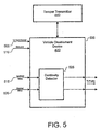
- Figure 5 illustrates an exemplary vehicle disablement device and tamper transmitter in accordance with the present invention
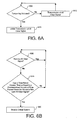
- Figure 6A illustrates an exemplary method for a tamper disabler transmitter in accordance with another exemplary embodiment of the present invention.
- Figure 6B illustrates an exemplary method for a tamper disabler receiver in accordance with another exemplary embodiment of the present invention.
- each of the exemplary embodiments of the invention there is provided apparatus for and methods of a tamper proof disablement of equipment. It will be appreciated that each of the embodiments described include both an apparatus and a method and that the apparatus and method of one exemplary embodiment may be different than the apparatus and method of another exemplary embodiment.
- FIG. 1 illustrates a vehicle with a vehicle disablement device and a tamper disabler device in accordance with exemplary embodiments of the present invention.
- a vehicle 110 is equipped with a vehicle disablement device 120 and a tamper disabler 130.
- a wireless signal is sent from the vehicle disablement device 120 to the tamper disabler 130.
- the wireless signal can be a radio frequency signal, an infrared signal or any other known type of wireless signal.
- the tamper disabler 130 can be located in any portion of vehicle 110.
- vehicle disablement device 120 and tamper disabler 130 since there are no wires connecting vehicle disablement device 120 and tamper disabler 130, it is difficult for a person who is attempting tamper with vehicle disablement device 120, from discovering the existence, let alone the location, of tamper disabler 130.
- vehicle disablement device 120 and tamper disabler 130 can be connected by a hard-wire connection.
- Figure 2 illustrates the relationship between a vehicle disablement 130 device, a critical system of a vehicle and a tamper disabler. As illustrated in figure 2, both the vehicle disablement device 120 and the tamper disabler are connected to a critical system 210 of a vehicle. Accordingly, if vehicle disablement device 120 is tampered with such that the device can no longer disable critical system 210, tamper disabler 130, upon receipt of a signal from vehicle disablement device 120, can still disable a critical system 210 of a vehicle.
- vehicle disablement device 120 may be powered by the vehicle, removing the vehicle disablement device 120 from the vehicle, e.g., by cutting the wires connecting the vehicle disablement device to the vehicle, the vehicle disablement device may no longer have power to send the signal to tamper disabler 130.
- the vehicle disablement device can be provided with a battery with a sufficient amount of power for sending the tamper disabling signal to the tamper disabler 130 in case the main source of power to the vehicle disablement device is removed.
- the vehicle disablement device may store power it has received from the vehicle such that when the vehicle's power to the vehicle disablement device 120 is removed the vehicle disablement device 120 can still transmit the tamper disabling signal.
- vehicle disablement device 120 can be powered by solar cells. The vehicle disablement device 120 can store this power via a capacitor, a rechargeable battery or any other known means for storing power. Since the vehicle disablement device 120 will only need to transmit the tamper disablement signal immediately after a tamper is detected, the amount of power that needs to be stored in the vehicle disablement device can be quite minimal.
- FIG. 3 illustrates an exemplary method in accordance with the present invention.
- the vehicle disablement device determines whether it has detected a tampering (step 310).
- the vehicle disablement device can detect a tampering by determining whether its power from the vehicle has been interrupted.
- the tampering can be detected based upon movement of the vehicle disablement device.
- the vehicle disablement device will be securely mounted in a vehicle. Accordingly, if a movement, other than normal movements due to driving, is detected the vehicle disablement device can determine that a tampering is taking place.
- the vehicle disablement device If the vehicle disablement device does not detect tampering ("NO" path out of decision step 310), the vehicle disablement device continues to monitor for tampering. If, however, the vehicle disablement device detects tampering ("YES" path out of decision step 310), then the vehicle disablement device sends a signal to the tamper disabler (step 320). The tamper disabler then disables a critical system of the vehicle, thereby preventing operation of the vehicle (step 330).
- Figure 4 illustrates a system which overcomes the above-identified drawbacks of the system and method described in connection with figures 1-3 by continuously transmitting a signal, and by employing the lack of receipt of the signal as trigger to disable the vehicle.
- a vehicle 410 includes a vehicle disablement device 420, a critical system 430, a tamper transmitter 440 and a tamper receiver 450.
- the tamper transmitter 440 can either be a component of the vehicle disablement device 420 or it can be a component separate from the vehicle disablement device 420, but with an interface for communicating with the vehicle disablement device 420.
- the vehicle disablement device 420 and the tamper receiver 450 are connected to a critical system 430 of the vehicle 410.
- Critical system 430 can be any type of system which prevents operation of the vehicle, including, but not limited to, the starter circuit, the ignition circuit or the fuel pump.
- FIG 4 illustrates the vehicle disablement device 420 as connected to the same critical system 430 as the tamper receiver 450, these devices can be connected to different critical systems of the vehicle.
- the vehicle disablement device may disable the starter circuit while the tamper receiver 450 may disable the fuel pump.
- the tamper transmitter 440 will continuously transmit a signal, which is herein referred to as an "all clear signal", to the tamper receiver 420.
- the all clear signal can be transmitted for approximately 600 milliseconds every two seconds. If the tamper transmitter detects that the vehicle disablement device is being tampered with, the tamper transmitter ceases the transmission of the all clear signal.
- the tamper receiver 450 determines that it has not received the all clear signal for a predetermined amount of time, e.g., 20 seconds, the tamper receiver 450 will disable a critical system 430.
- the vehicle disablement device 420 receives power from the vehicle's 12 volt power wire 505 and the ground wire 510.
- an ignition wire 515 from the vehicle's ignition (not shown), passes through a continuity detector 525, in the vehicle disablement device, and out of the vehicle disablement device 420 to the vehicle's engine (not shown).
- a starter wire 520 passes through continuity detector 525 in the vehicle disablement device 420 and continues on to the engine (not shown).
- the vehicle disablement device communicates with tamper transmitter 440 via bi-directional communication line 535.
- Continuity detector 525 is illustrated as a separate component within the vehicle disablement device 420 for ease of illustration. However, it should be recognized that continuity detector can be either a discrete component within the vehicle disablement device 420 or it could be a function performed by a microprocessor (not shown) of the vehicle disablement device. If the continuity detector functionality is performed by the microprocessor, this functionality will be contained either software code or hard-wired logic, either within the microprocessor itself or as a separate component the vehicle disablement device.
- the vehicle disablement device will contain a mechanism for disabling the vehicle.
- the vehicle disablement device could contain a relay which is set to open when an appropriate code has not been entered into the vehicle disablement device prior to the expiration of a payment due deadline.
- the relay could be arranged such that the starter wire or the ignition wire passes through the relay.
- the circuit for the other critical system will loop through a relay in the vehicle disablement device, thereby allowing the vehicle disablement device to disable the vehicle when an appropriate code has not been entered into the vehicle disablement device prior to the expiration of a payment due deadline.
- the vehicle disablement device If either the 12 volt power wire 505 or the ground wire 510 are cut, a tampering will be detected by the tamper transmitter. Specifically, the tamper transmitter will recognize that the power to the vehicle disablement device 420 has been cut, and therefore, the tamper transmitter will stop sending the all clear signal to the tamper receiver. If either the 12 volt power wire 505 or the ground wire 510 are cut, the tamper transmitter will stop sending the all clear signal regardless of whether a payment due deadline has passed without an associated code being entered into the vehicle disablement device.
- the vehicle disablement device will indicate to the tamper transmitter that a tampering has been detected. It will be recognized that if the ignition wire is cut and the starter is energized, this indicates that the starter has been energized by jumping the vehicle, for example, by rolling the vehicle down a hill and popping the vehicle into gear. If the ignition wire has been cut and the starter has been energized, the tamper transmitter will stop sending the all clear signal regardless of whether a payment due deadline has passed.
- the vehicle disablement device will inform the tamper transmitter that a tampering has been detected. The tamper transmitter will then stop sending the all clear signal. In addition, if it is determined that the starter has been energized by jumping the vehicle and if a payment due deadline has passed and a code associated with the payment due deadline has not been entered into the vehicle disablement device, the tamper transmitter will stop sending the all clear signal.
- the tamper transmitter will inhibit sending the all clear signal.
- Figure 6A illustrates an exemplary method for the tamper transmitter in accordance with the present invention.
- the tamper transmitter determines whether tampering has been detected (step 605). The determination of whether tampering has been detected can be performed using any of the techniques described above. If tampering has not been detected ("No" path out of decision step 605), then the tamper transmitter sends an all clear signal to the tamper receiver (step 610). After sending the all clear signal, the tamper transmitter again determines whether a tampering has been detected (step 605). If tampering has been detected ("Yes" path out of decision step 605), then the tamper transmitter inhibits the transmission of the all clear signal (step 615).
- Figure 6B illustrates an exemplary method for the tamper receiver in accordance with the present invention.
- the tamper receiver determines whether it has received an all clear signal from the tamper transmitter (step 620). If the tamper receiver has received an all clear signal ("Yes" path out of decision step 620), then the tamper receiver again determines whether an all clear signal has been received (step 620). If the tamper receiver determines that it has not received an all clear signal ("No" path out of decision step 620), then it is determined whether a period equal to or greater then a predetermined amount of time has passed since the last receipt of an all clear signal (step 625). In accordance with one embodiment of the present invention, the predetermined amount of time can be 20 seconds.
- the tamper receiver again determines whether it has received an all clear signal (step 620). If, however, a period of time equal to, or greater then, the predetermined amount of time has passed since the last receipt of an all clear signal ("Yes" path out of decision step 625), then the tamper receiver will disable a critical system of the vehicle (step 630).
- the method can also include the steps of: the user inputting the code into a time-based equipment disablement device; the time based disablement device comparing the code received from the user with codes stored in memory; and if there is a match, storing an indication in the time-based disablement device that the code has been entered, thereby allowing the user to operate the equipment associated with the time-based disablement device until the date and/or time associated with a code which has not been entered has occurred.
- the method can include the steps of: determining whether a date and/or time has occurred; if the date and/or time has occurred, determining whether a code associated with the date and/or time has been input into the time-based equipment disablement device; disabling the equipment if the code has not been previously entered; and allowing the equipment to operate if the code has been previously entered.
- the disablement device can include a plurality of lights, e.g., light emitting diodes, to indicate if the end of a payment period is upcoming. For example, a green light would indicate that no payment is due, a yellow light would indicate that a payment is due shortly, and a red light would indicate that a payment is due immediately or the equipment will be disabled.
- the lights can blink at an increasing frequency the closer in time it is to a payment due deadline.
- an audible beep or other sound can be used to indicate such.
- a single beep can be used to indicate that a payment is upcoming and a constant beep can indicate that a payment is passed due.
- vehicle disablement device detects the tampering and sends a signal to the tamper disabler
- another device can be used to perform the detecting and sending.
- the tamper disabler can perform the detecting, thereby obviating the sending step.
Landscapes
- Engineering & Computer Science (AREA)
- Mechanical Engineering (AREA)
- Lock And Its Accessories (AREA)
- Mobile Radio Communication Systems (AREA)
- Burglar Alarm Systems (AREA)
- Fire Alarms (AREA)
- Transmitters (AREA)
- Emergency Alarm Devices (AREA)
Claims (19)
- System für die Deaktivierung eines Fahrzeugs, wobei das Fahrzeug ein kritisches System umfasst, wobei das System aufweist:eine Fahrzeugdeaktivierungsvorrichtung, wobei die Fahrzeugdeaktivierungsvorrichtung das kritische System des Fahrzeugs deaktiviert, wenn eine Zahlung für das Fahrzeug nicht bis zu einem fälligen Zahlungstermin geleistet wird, wobei die Deaktivierung des kritischen Systems den Betrieb des Fahrzeugs verhindert;einen Sender für unbefugtes Eingreifen, wobei der Sender für unbefugtes Eingreifen periodisch ein Signal sendet; undeinen Empfänger für unbefugtes Eingreifen, wobei der Empfänger für unbefugtes Eingreifen ein kritisches System deaktiviert, wenn von dem Sender für unbefugtes Eingreifen in einem vorherbestimmten Zeitraum kein Signal empfangen wird.
- System nach Anspruch 1, wobei der Sender für unbefugtes Eingreifen die Übertragung des Signals sperrt, wenn ein unbefugtes Eingreifen am Fahrzeug detektiert wird.
- System nach Anspruch 2, wobei der Sender für unbefugtes Eingreifen das unbefugte Eingreifen detektiert.
- System nach Anspruch 3, wobei das von dem Sender für unbefugtes Eingreifen detektierte unbefugte Eingreifen unbefugt in die Fahrzeugdeaktivierungsvorrichtung eingreift.
- System nach Anspruch 1, wobei das von der Fahrzeugdeaktivierungsvorrichtung deaktivierte kritische System und das von dem Empfänger für unbefugtes Eingreifen deaktivierte kritische System verschiedene kritische Systeme sind.
- System nach Anspruch 5, wobei das von der Fahrzeugdeaktivierungsvorrichtung deaktivierte kritische System eine Anlasserschaltung des Fahrzeugs ist und das von dem Empfänger für unbefugtes Eingreifen deaktivierte kritische System eine Kraftstoffleitung des Fahrzeugs ist.
- System nach Anspruch 1, wobei das Fahrzeug ein Kraftfahrzeug ist.
- System nach Anspruch 1, wobei der Sender für unbefugtes Eingreifen und der Empfänger für unbefugtes Eingreifen über eine festverdrahtete Verbindung miteinander kommunizieren.
- System nach Anspruch 1, wobei der Sender für unbefugtes Eingreifen und der Empfänger für unbefugtes Eingreifen über eine drahtlose Verbindung miteinander kommunizieren.
- System nach Anspruch 1, wobei der Sender für unbefugtes Eingreifen ein Bestandteil der Fahrzeugdeaktivierungsvorrichtung ist.
- System nach Anspruch 1, wobei der Sender für unbefugtes Eingreifen ein von der Fahrzeugdeaktivierungsvorrichtung getrennter Bestandteil ist und der Sender für unbefugtes Eingreifen eine Schnittstelle mit der Fahrzeugdeaktivierungsvorrichtung hat.
- System nach Anspruch 1, wobei die Fahrzeugdeaktivierungsvorrichtung ferner aufweist:rote, gelbe und grüne Lichter, die leuchten, um anzuzeigen, ob eine Zahlung für das Fahrzeug fällig ist.
- Verfahren für die Deaktivierung eines Fahrzeugs, das folgende Schritte aufweist:periodisches Senden eines Signals von einem Sender für unbefugtes Eingreifen an einen Empfänger für unbefugtes Eingreifen;Bestimmen durch einen Sender für unbefugtes Eingreifen, ob unbefugt am Fahrzeug eingegriffen wird;Sperren des periodischen Sendens des Signals, wenn ein unbefugtes Eingreifen am Fahrzeug bestimmt wird; undDeaktivieren des Fahrzeugs, wenn das periodische Senden des Signals gesperrt wird.
- Verfahren nach Anspruch 13, wobei der Deaktivierungsschritt den folgenden Schritt aufweist:Bestimmen durch den Empfänger für unbefugtes Eingreifen, ob eine vorherbestimmte Zeitspanne vergangen ist, seit das letzte periodische Signal empfangen wurde; undDeaktivieren eines kritischen Systems des Fahrzeugs durch den Empfänger für unbefugtes Eingreifen, wenn bestimmt wird, dass die vorherbestimmte Zeitspanne vergangen ist, seit das letzte periodische Signal empfangen wurde.
- Verfahren nach Anspruch 14, wobei der Schritt der Deaktivierung eines kritischen Systems ferner den folgenden Schritt umfasst:Unterbrechen der Energie zu einer Treibstoffpumpe des Fahrzeugs.
- Verfahren nach Anspruch 14, das ferner folgende Schritte umfasst:Bestimmen, ob ein Code vor einem Fälligkeitsdatum in eine Fahrzeugdeaktivierungsvorrichtung eingegeben wurde; undDeaktivieren eines kritischen Systems des Fahrzeugs durch die Fahrzeugdeaktivierungsvorrichtung, wenn ein Code nicht vor dem Fälligkeitsdatum eingegeben wurde, wobei das von dem Empfänger für unbefugtes Eingreifen deaktivierte kritische System und das von der Fahrzeugdeaktivierungsvorrichtung deaktivierte kritische System verschiedene Systeme sind.
- Verfahren nach Anspruch 13, wobei der Sender für unbefugtes Eingreifen eine Schnittstelle mit einer Fahrzeugdeaktivierungsvorrichtung hat und die Frage, ob am Fahrzeug unbefugt eingegriffen wird, durch Detektieren, dass eine Energieleitung der Fahrzeugdeaktivierungsvorrichtung durchtrennt wurde, Detektieren, dass eine Masseleitung der Fahrzeugdeaktivierungsvorrichtung durchtrennt wurde, Detektieren, ob eine durch die Fahrzeugdeaktivierungsvorrichtung verlaufende Anlasserleitung durchschnitten wurde, detektiert wird.
- Verfahren nach Anspruch 13, wobei das Fahrzeug durch die Deaktivierung eines kritischen Systems des Fahrzeugs deaktiviert wird.
- Verfahren nach Anspruch 13, ferner aufweisend eine Deaktivierung des Fahrzeugs durch Deaktivierung eines mit der Fahrzeugdeaktivierungsvorrichtung gekoppelten kritischen Systems des Fahrzeugs durch die Fahrzeugdeaktivierungsvorrichtung, um den Betrieb des Fahrzeugs zu verhindern, wenn eine Zahlung für das Fahrzeug nicht bis zu einem fälligen Zahlungstermin geleistet wurde.
Applications Claiming Priority (3)
| Application Number | Priority Date | Filing Date | Title |
|---|---|---|---|
| US10/151,037 US6828692B2 (en) | 2002-05-21 | 2002-05-21 | Tampering detector and system disabler |
| US151037 | 2002-05-21 | ||
| PCT/US2003/014665 WO2003100805A1 (en) | 2002-05-21 | 2003-05-12 | Tampering detector and system disabler |
Publications (3)
| Publication Number | Publication Date |
|---|---|
| EP1508149A1 EP1508149A1 (de) | 2005-02-23 |
| EP1508149A4 EP1508149A4 (de) | 2005-08-10 |
| EP1508149B1 true EP1508149B1 (de) | 2006-09-20 |
Family
ID=29548363
Family Applications (1)
| Application Number | Title | Priority Date | Filing Date |
|---|---|---|---|
| EP03728800A Expired - Lifetime EP1508149B1 (de) | 2002-05-21 | 2003-05-12 | Manipulationsdetektor und system-sperrvorrichtung |
Country Status (11)
| Country | Link |
|---|---|
| US (1) | US6828692B2 (de) |
| EP (1) | EP1508149B1 (de) |
| CN (1) | CN100342469C (de) |
| AT (1) | ATE340111T1 (de) |
| AU (1) | AU2003233523B2 (de) |
| CA (1) | CA2486367A1 (de) |
| DE (1) | DE60308514D1 (de) |
| MX (1) | MXPA04011407A (de) |
| NZ (1) | NZ536566A (de) |
| PL (1) | PL372629A1 (de) |
| WO (1) | WO2003100805A1 (de) |
Families Citing this family (35)
| Publication number | Priority date | Publication date | Assignee | Title |
|---|---|---|---|---|
| US7359773B2 (en) * | 2003-07-09 | 2008-04-15 | Payment Protection Systems, Inc. | Wireless relay for payment enforcement devices and method of using same |
| US7650509B1 (en) | 2004-01-28 | 2010-01-19 | Gordon & Howard Associates, Inc. | Encoding data in a password |
| MX2007004848A (es) * | 2004-10-25 | 2007-08-22 | Payment Protection Sys Inc | Metodo y sistema para monitorear un vehiculo. |
| US20070194881A1 (en) | 2006-02-07 | 2007-08-23 | Schwarz Stanley G | Enforcing payment schedules |
| US7538655B1 (en) | 2006-05-02 | 2009-05-26 | King Kevin M | Interactive wireless vehicle immobilizer |
| US20080091590A1 (en) * | 2006-10-17 | 2008-04-17 | Gary Kremen | Methods, systems and financial instruments for financing renewable energy consumer premises equipment |
| US7890436B2 (en) * | 2006-10-17 | 2011-02-15 | Clean Power Finance, Inc. | Billing and payment methods and systems enabling consumer premises equipment |
| US20080091626A1 (en) * | 2006-10-17 | 2008-04-17 | Gary Kremen | Systems, methods and financial instruments for renewable energy consumer premises equipment financing |
| US20110202446A1 (en) * | 2006-10-17 | 2011-08-18 | Gary Kremen | Method and system for grouping and marketing consumer premises equipment loans |
| US20080091580A1 (en) * | 2006-10-17 | 2008-04-17 | Gary Kremen | Methods for cost reduction and underwriting considerations for financing renewable energy consumer premises equipment (CPE) |
| US20080091589A1 (en) * | 2006-10-17 | 2008-04-17 | Gary Kremen | Method for underwriting the financing of solar consumer premises equipment |
| US7698219B2 (en) * | 2007-01-12 | 2010-04-13 | Clean Power Finance, Inc. | Methods, systems and agreements for increasing the likelihood of repayments under a financing agreement for renewable energy equipment |
| US9031874B2 (en) * | 2007-01-12 | 2015-05-12 | Clean Power Finance, Inc. | Methods, systems and agreements for increasing the likelihood of repayments under a financing agreement for renewable energy equipment |
| US20080221743A1 (en) * | 2007-03-09 | 2008-09-11 | Gordon * Howard Associates, Inc. | Onboard Starter-Interrupt Device Incorporating Wireless Personal Area Network |
| US9026267B2 (en) | 2007-03-09 | 2015-05-05 | Gordon*Howard Associates, Inc. | Methods and systems of selectively enabling a vehicle by way of a portable wireless device |
| US20090024541A1 (en) * | 2007-07-20 | 2009-01-22 | Gary Kremen | Power purchase methods, agreements and financial instruments for tax-advantaged financing residential renewable energy equipment |
| US8581712B2 (en) | 2008-12-12 | 2013-11-12 | Gordon * Howard Associates, Inc . | Methods and systems related to establishing geo-fence boundaries |
| US8659404B2 (en) | 2008-12-12 | 2014-02-25 | Gordon Howard Associates, Inc. | Methods and systems related to establishing geo-fence boundaries and collecting data |
| US8018329B2 (en) | 2008-12-12 | 2011-09-13 | Gordon * Howard Associates, Inc. | Automated geo-fence boundary configuration and activation |
| US8686841B2 (en) | 2008-12-12 | 2014-04-01 | Gordon*Howard Associates, Inc. | Methods and systems related to activating geo-fence boundaries and collecting location data |
| US8725330B2 (en) | 2010-06-02 | 2014-05-13 | Bryan Marc Failing | Increasing vehicle security |
| US8581711B2 (en) | 2011-03-22 | 2013-11-12 | Gordon*Howard Associates, Inc. | Methods and systems of rule-based intoxicating substance testing associated with vehicles |
| US8781900B2 (en) | 2011-09-09 | 2014-07-15 | Gordon*Howard Associates, Inc. | Method and system of providing information to an occupant of a vehicle |
| JP5767998B2 (ja) * | 2012-03-30 | 2015-08-26 | クラリオン株式会社 | 車載機およびその制御方法と遠隔操作システム |
| US9665997B2 (en) | 2013-01-08 | 2017-05-30 | Gordon*Howard Associates, Inc. | Method and system for providing feedback based on driving behavior |
| US9840229B2 (en) | 2013-03-14 | 2017-12-12 | Gordon*Howard Associates, Inc. | Methods and systems related to a remote tamper detection |
| US8928471B2 (en) | 2013-03-14 | 2015-01-06 | Gordon*Howard Associates, Inc. | Methods and systems related to remote tamper detection |
| US9035756B2 (en) | 2013-03-14 | 2015-05-19 | Gordon*Howard Associates, Inc. | Methods and systems related to remote tamper detection |
| US9378480B2 (en) | 2013-03-14 | 2016-06-28 | Gordon*Howard Associates, Inc. | Methods and systems related to asset identification triggered geofencing |
| US9013333B2 (en) | 2013-06-24 | 2015-04-21 | Gordon*Howard Associates, Inc. | Methods and systems related to time triggered geofencing |
| US9701279B1 (en) | 2016-01-12 | 2017-07-11 | Gordon*Howard Associates, Inc. | On board monitoring device |
| CN107234967B (zh) * | 2017-05-15 | 2019-04-02 | 东莞市中港通电子科技有限公司 | 一种防范车贷风险的系统及方法 |
| US10733473B2 (en) | 2018-09-20 | 2020-08-04 | Uber Technologies Inc. | Object verification for a network-based service |
| US10999299B2 (en) | 2018-10-09 | 2021-05-04 | Uber Technologies, Inc. | Location-spoofing detection system for a network service |
| US11816936B2 (en) | 2018-12-03 | 2023-11-14 | Bendix Commercial Vehicle Systems, Llc | System and method for detecting driver tampering of vehicle information systems |
Family Cites Families (23)
| Publication number | Priority date | Publication date | Assignee | Title |
|---|---|---|---|---|
| US40504A (en) * | 1863-11-03 | Improvement in fluid-meters | ||
| US4736195A (en) * | 1987-02-24 | 1988-04-05 | Associates West, Inc. | Method and apparatus for warning of disconnection of an appliance from a power source |
| FR2661878B1 (fr) * | 1990-05-14 | 1994-03-11 | Sebty Sarl | Dispositif antivol pour vehicules automobiles par coupure inviolable de l'alimentation en combustible. |
| US5291554A (en) | 1992-05-28 | 1994-03-01 | Tv Answer, Inc. | Shared-price custom video rentals via interactive TV |
| US5381128A (en) | 1992-09-10 | 1995-01-10 | Kaplan; Neil B. | Vehicle security system with emergency override |
| US5307048A (en) * | 1992-12-18 | 1994-04-26 | Protect & Defend, Inc. | Vehicle security system including an anti-carjacking system |
| US5673305A (en) | 1993-05-14 | 1997-09-30 | Worldwide Notification Systems, Inc. | Apparatus and method for tracking and reporting the location of a motor vehicle |
| US5513244A (en) | 1993-06-08 | 1996-04-30 | Joao; Raymond A. | Remote-controlled anti-theft, theft reporting, or vehicle recovery system and method for motor vehicles |
| US5708417A (en) * | 1993-12-16 | 1998-01-13 | Phone Alert Corp. | Monitoring system for remote units |
| US5510780A (en) | 1994-02-18 | 1996-04-23 | Profit Plus Corporation | Time cycled security code and activation control system |
| US5793122A (en) | 1996-06-11 | 1998-08-11 | Motor Vehicle Protection Systems, Inc. | Automobile security device |
| US6021399A (en) | 1996-11-25 | 2000-02-01 | Xerox Corporation | Space efficient method of verifying electronic payments |
| US6232884B1 (en) | 1997-01-02 | 2001-05-15 | Charles H. Gabbard | Remotely operable vehicle disabling system |
| US6611201B1 (en) * | 1997-12-16 | 2003-08-26 | Ventronix Corporation | Method and apparatus for accessing, monitoring and controlled specified functions, features and accessories of a vehicle |
| WO1999035014A1 (en) * | 1998-01-05 | 1999-07-15 | Gabbard Charles H | Remotely operable vehicle disabling system |
| US6411217B1 (en) * | 1998-05-19 | 2002-06-25 | Charles H. Gabbard | Vehicle disabling system |
| US6124805A (en) | 1998-05-19 | 2000-09-26 | Gabbard; Charles H. | Remotely operable vehicle identification and disabling system |
| US6206130B1 (en) * | 1998-06-08 | 2001-03-27 | Leslie L. Hetler | Vehicle anti-theft device |
| US6025774A (en) | 1998-06-24 | 2000-02-15 | Forbes; Mark P. | Method for retrieving vehicular collateral |
| US6195648B1 (en) * | 1999-08-10 | 2001-02-27 | Frank Simon | Loan repay enforcement system |
| US6310542B1 (en) | 1999-08-19 | 2001-10-30 | Lucent Technologies Inc. | Cognitive system for a vehicle and its occupants |
| US6870467B2 (en) * | 2000-09-29 | 2005-03-22 | Payment Protection Systems, Inc. | Tampering detector and system disabler |
| JP3672244B2 (ja) * | 2001-05-01 | 2005-07-20 | インターナショナル・ビジネス・マシーンズ・コーポレーション | 制御方法、受信システム、制御システムおよびプログラム |
-
2002
- 2002-05-21 US US10/151,037 patent/US6828692B2/en not_active Expired - Lifetime
-
2003
- 2003-05-12 AU AU2003233523A patent/AU2003233523B2/en not_active Ceased
- 2003-05-12 WO PCT/US2003/014665 patent/WO2003100805A1/en not_active Ceased
- 2003-05-12 CA CA002486367A patent/CA2486367A1/en not_active Abandoned
- 2003-05-12 DE DE60308514T patent/DE60308514D1/de not_active Expired - Lifetime
- 2003-05-12 MX MXPA04011407A patent/MXPA04011407A/es active IP Right Grant
- 2003-05-12 NZ NZ536566A patent/NZ536566A/en unknown
- 2003-05-12 AT AT03728800T patent/ATE340111T1/de not_active IP Right Cessation
- 2003-05-12 CN CNB038116189A patent/CN100342469C/zh not_active Expired - Fee Related
- 2003-05-12 EP EP03728800A patent/EP1508149B1/de not_active Expired - Lifetime
- 2003-05-12 PL PL03372629A patent/PL372629A1/xx unknown
Also Published As
| Publication number | Publication date |
|---|---|
| ATE340111T1 (de) | 2006-10-15 |
| US6828692B2 (en) | 2004-12-07 |
| NZ536566A (en) | 2007-05-31 |
| AU2003233523B2 (en) | 2008-10-09 |
| HK1082119A1 (en) | 2006-05-26 |
| MXPA04011407A (es) | 2005-02-14 |
| AU2003233523A1 (en) | 2003-12-12 |
| CN1656586A (zh) | 2005-08-17 |
| CN100342469C (zh) | 2007-10-10 |
| PL372629A1 (en) | 2005-07-25 |
| DE60308514D1 (de) | 2006-11-02 |
| CA2486367A1 (en) | 2003-12-04 |
| WO2003100805A1 (en) | 2003-12-04 |
| US20030218382A1 (en) | 2003-11-27 |
| EP1508149A4 (de) | 2005-08-10 |
| EP1508149A1 (de) | 2005-02-23 |
Similar Documents
| Publication | Publication Date | Title |
|---|---|---|
| EP1508149B1 (de) | Manipulationsdetektor und system-sperrvorrichtung | |
| US7359773B2 (en) | Wireless relay for payment enforcement devices and method of using same | |
| US6870467B2 (en) | Tampering detector and system disabler | |
| US20230030023A1 (en) | Vehicle remote control system | |
| US20220379839A1 (en) | Vehicle door locking and unlocking vehicle-mounted device, vehicle including vehicle-mounted device, and vehicle door locking and unlocking system including vehicle-mounted device | |
| US6489897B2 (en) | Vehicle location system | |
| US20220169202A1 (en) | Vehicle remote control system, communication module, vehicle, server, vehicle remote control method, vehicle remote control program, and storage medium | |
| US6809659B2 (en) | Vehicle tracker with test features and related methods | |
| US20010028295A1 (en) | Electronic vehicle key | |
| US11155236B2 (en) | Method and a system for controlling and monitoring operation of a device | |
| US20160090923A1 (en) | Payment enforcement system | |
| CN1846385A (zh) | 付款增强装置的无线继电器及其用法 | |
| HK1082119B (en) | System and method for disabling a vehicle |
Legal Events
| Date | Code | Title | Description |
|---|---|---|---|
| PUAI | Public reference made under article 153(3) epc to a published international application that has entered the european phase |
Free format text: ORIGINAL CODE: 0009012 |
|
| 17P | Request for examination filed |
Effective date: 20041201 |
|
| AK | Designated contracting states |
Kind code of ref document: A1 Designated state(s): AT BE BG CH CY CZ DE DK EE ES FI FR GB GR HU IE IT LI LU MC NL PT RO SE SI SK TR |
|
| AX | Request for extension of the european patent |
Extension state: AL LT LV MK |
|
| A4 | Supplementary search report drawn up and despatched |
Effective date: 20050627 |
|
| RIC1 | Information provided on ipc code assigned before grant |
Ipc: 7B 60R 25/04 A |
|
| DAX | Request for extension of the european patent (deleted) | ||
| GRAP | Despatch of communication of intention to grant a patent |
Free format text: ORIGINAL CODE: EPIDOSNIGR1 |
|
| GRAS | Grant fee paid |
Free format text: ORIGINAL CODE: EPIDOSNIGR3 |
|
| GRAA | (expected) grant |
Free format text: ORIGINAL CODE: 0009210 |
|
| AK | Designated contracting states |
Kind code of ref document: B1 Designated state(s): AT BE BG CH CY CZ DE DK EE ES FI FR GB GR HU IE IT LI LU MC NL PT RO SE SI SK TR |
|
| PG25 | Lapsed in a contracting state [announced via postgrant information from national office to epo] |
Ref country code: IT Free format text: LAPSE BECAUSE OF FAILURE TO SUBMIT A TRANSLATION OF THE DESCRIPTION OR TO PAY THE FEE WITHIN THE PRESCRIBED TIME-LIMIT;WARNING: LAPSES OF ITALIAN PATENTS WITH EFFECTIVE DATE BEFORE 2007 MAY HAVE OCCURRED AT ANY TIME BEFORE 2007. THE CORRECT EFFECTIVE DATE MAY BE DIFFERENT FROM THE ONE RECORDED. Effective date: 20060920 Ref country code: CZ Free format text: LAPSE BECAUSE OF FAILURE TO SUBMIT A TRANSLATION OF THE DESCRIPTION OR TO PAY THE FEE WITHIN THE PRESCRIBED TIME-LIMIT Effective date: 20060920 Ref country code: FI Free format text: LAPSE BECAUSE OF FAILURE TO SUBMIT A TRANSLATION OF THE DESCRIPTION OR TO PAY THE FEE WITHIN THE PRESCRIBED TIME-LIMIT Effective date: 20060920 Ref country code: BE Free format text: LAPSE BECAUSE OF FAILURE TO SUBMIT A TRANSLATION OF THE DESCRIPTION OR TO PAY THE FEE WITHIN THE PRESCRIBED TIME-LIMIT Effective date: 20060920 Ref country code: LI Free format text: LAPSE BECAUSE OF FAILURE TO SUBMIT A TRANSLATION OF THE DESCRIPTION OR TO PAY THE FEE WITHIN THE PRESCRIBED TIME-LIMIT Effective date: 20060920 Ref country code: CH Free format text: LAPSE BECAUSE OF FAILURE TO SUBMIT A TRANSLATION OF THE DESCRIPTION OR TO PAY THE FEE WITHIN THE PRESCRIBED TIME-LIMIT Effective date: 20060920 Ref country code: AT Free format text: LAPSE BECAUSE OF FAILURE TO SUBMIT A TRANSLATION OF THE DESCRIPTION OR TO PAY THE FEE WITHIN THE PRESCRIBED TIME-LIMIT Effective date: 20060920 Ref country code: SI Free format text: LAPSE BECAUSE OF FAILURE TO SUBMIT A TRANSLATION OF THE DESCRIPTION OR TO PAY THE FEE WITHIN THE PRESCRIBED TIME-LIMIT Effective date: 20060920 Ref country code: NL Free format text: LAPSE BECAUSE OF FAILURE TO SUBMIT A TRANSLATION OF THE DESCRIPTION OR TO PAY THE FEE WITHIN THE PRESCRIBED TIME-LIMIT Effective date: 20060920 Ref country code: SK Free format text: LAPSE BECAUSE OF FAILURE TO SUBMIT A TRANSLATION OF THE DESCRIPTION OR TO PAY THE FEE WITHIN THE PRESCRIBED TIME-LIMIT Effective date: 20060920 Ref country code: RO Free format text: LAPSE BECAUSE OF FAILURE TO SUBMIT A TRANSLATION OF THE DESCRIPTION OR TO PAY THE FEE WITHIN THE PRESCRIBED TIME-LIMIT Effective date: 20060920 |
|
| REG | Reference to a national code |
Ref country code: GB Ref legal event code: FG4D |
|
| REG | Reference to a national code |
Ref country code: CH Ref legal event code: EP |
|
| REG | Reference to a national code |
Ref country code: IE Ref legal event code: FG4D |
|
| REF | Corresponds to: |
Ref document number: 60308514 Country of ref document: DE Date of ref document: 20061102 Kind code of ref document: P |
|
| PG25 | Lapsed in a contracting state [announced via postgrant information from national office to epo] |
Ref country code: SE Free format text: LAPSE BECAUSE OF FAILURE TO SUBMIT A TRANSLATION OF THE DESCRIPTION OR TO PAY THE FEE WITHIN THE PRESCRIBED TIME-LIMIT Effective date: 20061220 Ref country code: BG Free format text: LAPSE BECAUSE OF FAILURE TO SUBMIT A TRANSLATION OF THE DESCRIPTION OR TO PAY THE FEE WITHIN THE PRESCRIBED TIME-LIMIT Effective date: 20061220 Ref country code: DK Free format text: LAPSE BECAUSE OF FAILURE TO SUBMIT A TRANSLATION OF THE DESCRIPTION OR TO PAY THE FEE WITHIN THE PRESCRIBED TIME-LIMIT Effective date: 20061220 |
|
| PG25 | Lapsed in a contracting state [announced via postgrant information from national office to epo] |
Ref country code: DE Free format text: LAPSE BECAUSE OF FAILURE TO SUBMIT A TRANSLATION OF THE DESCRIPTION OR TO PAY THE FEE WITHIN THE PRESCRIBED TIME-LIMIT Effective date: 20061221 |
|
| PG25 | Lapsed in a contracting state [announced via postgrant information from national office to epo] |
Ref country code: ES Free format text: LAPSE BECAUSE OF FAILURE TO SUBMIT A TRANSLATION OF THE DESCRIPTION OR TO PAY THE FEE WITHIN THE PRESCRIBED TIME-LIMIT Effective date: 20061231 |
|
| NLV1 | Nl: lapsed or annulled due to failure to fulfill the requirements of art. 29p and 29m of the patents act | ||
| PG25 | Lapsed in a contracting state [announced via postgrant information from national office to epo] |
Ref country code: PT Free format text: LAPSE BECAUSE OF FAILURE TO SUBMIT A TRANSLATION OF THE DESCRIPTION OR TO PAY THE FEE WITHIN THE PRESCRIBED TIME-LIMIT Effective date: 20070312 |
|
| REG | Reference to a national code |
Ref country code: CH Ref legal event code: PL |
|
| EN | Fr: translation not filed | ||
| PLBE | No opposition filed within time limit |
Free format text: ORIGINAL CODE: 0009261 |
|
| STAA | Information on the status of an ep patent application or granted ep patent |
Free format text: STATUS: NO OPPOSITION FILED WITHIN TIME LIMIT |
|
| 26N | No opposition filed |
Effective date: 20070621 |
|
| PG25 | Lapsed in a contracting state [announced via postgrant information from national office to epo] |
Ref country code: MC Free format text: LAPSE BECAUSE OF NON-PAYMENT OF DUE FEES Effective date: 20070531 |
|
| PG25 | Lapsed in a contracting state [announced via postgrant information from national office to epo] |
Ref country code: FR Free format text: LAPSE BECAUSE OF FAILURE TO SUBMIT A TRANSLATION OF THE DESCRIPTION OR TO PAY THE FEE WITHIN THE PRESCRIBED TIME-LIMIT Effective date: 20070518 Ref country code: GR Free format text: LAPSE BECAUSE OF FAILURE TO SUBMIT A TRANSLATION OF THE DESCRIPTION OR TO PAY THE FEE WITHIN THE PRESCRIBED TIME-LIMIT Effective date: 20061221 |
|
| PG25 | Lapsed in a contracting state [announced via postgrant information from national office to epo] |
Ref country code: IE Free format text: LAPSE BECAUSE OF NON-PAYMENT OF DUE FEES Effective date: 20070514 |
|
| PG25 | Lapsed in a contracting state [announced via postgrant information from national office to epo] |
Ref country code: EE Free format text: LAPSE BECAUSE OF FAILURE TO SUBMIT A TRANSLATION OF THE DESCRIPTION OR TO PAY THE FEE WITHIN THE PRESCRIBED TIME-LIMIT Effective date: 20060920 |
|
| PG25 | Lapsed in a contracting state [announced via postgrant information from national office to epo] |
Ref country code: FR Free format text: LAPSE BECAUSE OF FAILURE TO SUBMIT A TRANSLATION OF THE DESCRIPTION OR TO PAY THE FEE WITHIN THE PRESCRIBED TIME-LIMIT Effective date: 20060920 |
|
| PG25 | Lapsed in a contracting state [announced via postgrant information from national office to epo] |
Ref country code: LU Free format text: LAPSE BECAUSE OF NON-PAYMENT OF DUE FEES Effective date: 20070512 Ref country code: CY Free format text: LAPSE BECAUSE OF FAILURE TO SUBMIT A TRANSLATION OF THE DESCRIPTION OR TO PAY THE FEE WITHIN THE PRESCRIBED TIME-LIMIT Effective date: 20060920 |
|
| PG25 | Lapsed in a contracting state [announced via postgrant information from national office to epo] |
Ref country code: HU Free format text: LAPSE BECAUSE OF FAILURE TO SUBMIT A TRANSLATION OF THE DESCRIPTION OR TO PAY THE FEE WITHIN THE PRESCRIBED TIME-LIMIT Effective date: 20070321 Ref country code: TR Free format text: LAPSE BECAUSE OF FAILURE TO SUBMIT A TRANSLATION OF THE DESCRIPTION OR TO PAY THE FEE WITHIN THE PRESCRIBED TIME-LIMIT Effective date: 20060920 |
|
| PGFP | Annual fee paid to national office [announced via postgrant information from national office to epo] |
Ref country code: GB Payment date: 20090506 Year of fee payment: 7 |
|
| GBPC | Gb: european patent ceased through non-payment of renewal fee |
Effective date: 20100512 |
|
| PG25 | Lapsed in a contracting state [announced via postgrant information from national office to epo] |
Ref country code: GB Free format text: LAPSE BECAUSE OF NON-PAYMENT OF DUE FEES Effective date: 20100512 |