EP1508291A2 - Vorrichtung bestehend aus einer Sanitärarmatur und einer Befestigungsvorrichtung für ein Accessoireteil - Google Patents
Vorrichtung bestehend aus einer Sanitärarmatur und einer Befestigungsvorrichtung für ein Accessoireteil Download PDFInfo
- Publication number
- EP1508291A2 EP1508291A2 EP04015962A EP04015962A EP1508291A2 EP 1508291 A2 EP1508291 A2 EP 1508291A2 EP 04015962 A EP04015962 A EP 04015962A EP 04015962 A EP04015962 A EP 04015962A EP 1508291 A2 EP1508291 A2 EP 1508291A2
- Authority
- EP
- European Patent Office
- Prior art keywords
- building wall
- sanitary fitting
- fitting
- accessory
- arrangement according
- Prior art date
- Legal status (The legal status is an assumption and is not a legal conclusion. Google has not performed a legal analysis and makes no representation as to the accuracy of the status listed.)
- Withdrawn
Links
Images


Classifications
-
- E—FIXED CONSTRUCTIONS
- E03—WATER SUPPLY; SEWERAGE
- E03C—DOMESTIC PLUMBING INSTALLATIONS FOR FRESH WATER OR WASTE WATER; SINKS
- E03C1/00—Domestic plumbing installations for fresh water or waste water; Sinks
- E03C1/02—Plumbing installations for fresh water
- E03C1/04—Water-basin installations specially adapted to wash-basins or baths
- E03C1/042—Arrangements on taps for wash-basins or baths for connecting to the wall
Definitions
- the invention relates to an arrangement of a sanitary fitting and a fastening device, with the Sanitary fitting is connectable and the holder of a Accessory parts serves.
- Accessory parts are, for example, the so-called “dry fittings”, in particular holders for toothbrush cups, Soap dishes, lotion containers, towel and Handrails and the like count.
- As accessory parts come but also water-bearing elements, for example an overhead shower pipes, in question.
- the object of the present invention is an arrangement to create the type mentioned, in which also heavier accessory parts in a visually appealing way can be attached to the sanitary fitting.
- the space that is on surface-mounted fittings between the back and the building wall available is used to accommodate those components, which is required for attachment of the accessory part are.
- the surface-mounted fitting can essentially opposite remain unchanged in their conventional design; as the only modification must be the fastener be provided at the rear of the fitting where it deprived of the user's gaze.
- the fastener can be designed so that the other, required for attaching the accessory part components if necessary with his help on the sanitary fitting can be set without the sanitary fitting be removed from this or the house lines would. So it is always a retrofit of sanitary fitting possible, provided that this only works with the this required fastening means is provided.
- the attachment means may be in the simplest case, a threaded bore incorporated in the fitting body.
- a screw can be screwed, which then only has to be tightened to attach the accessory part, which is easily possible even under the cramped space between the rear of the surface-mounted fitting and the building wall.
- a Holding part provided, which by means of the fastener on the side facing the building wall of the sanitary fitting is fastened.
- the accessory part will be so not directly but with the help of the intermediary Holding parts connected to the sanitary fitting.
- the holding part is a standardized, for different accessory parts matching component.
- the mounting of the holding part to the sanitary fitting is at facilitates that embodiment of the invention, in which the holding part at least one passage opening has, which is slotted so that the holding part by a movement taking place parallel to the building wall Screw can be pushed and fixed by tightening the screw is.
- the holding part may have a fastening projection, in a recess of a holding adapter for the accessory parts or the accessory itself einschiebbar and can be fixed there.
- This embodiment of the invention facilitates the assembly of the accessory part in the relatively cramped space between the back the sanitary fitting and the building wall is available.
- the accessory part can in particular be a holding rod for a dry fitting but also a water-bearing element be.
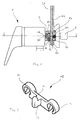
- FIG. 1 In this is a surface-mounted mixer tap in the form of a single-lever mixer marked with the reference numeral 1.
- the single-lever mixer 1 At the facing away from the user in the mounting position, not the shown building wall adjacent rear 2 the single-lever mixer 1 are in a known manner two water connections 3, 4 at a certain distance from each other provided away.
- S-connections 5, 6 mounted On the water connections 3, 4 are S-connections 5, 6 mounted, one of the gauge of the Single-lever mixer 1 different gauge of house lines, which are not shown in the drawing and to which the one-lever mixer 1 is connected, compensate.
- the holding part 10 has two passage openings 11, 12, their center distance with the center distance of the two threaded holes 8, 9 of the fitting body 7 matches.
- the Through holes 11, 12 are slotted downwards.
- In the middle area between the two passage openings 11, 12 is an angled Befest Trentsvörsprung to the holding part 10 13 molded, the one facing up, rounded Nose 14 owns.
- the holding adapter 15 has for this purpose a recess 16, which opens to the side that the holding part 10 is adjacent.
- the recess 16 is so large that the fastening projection 13 together with the Nose 14 by taking place perpendicular to the building wall Movement of the holding adapter 15 can be inserted.
- the recess 16 points at a certain distance from the side surface of the holding adapter 15 an upward guided tap hole 17, in which the nose 14 of the Mounting projection 13 can be added, as this is shown in FIG.
- the lower end face of the holding adapter 15 is connected to the recess 16 by a Threaded contact 18 connected, in which a grub screw 19 is screwed.
- the holding adapter 15 is also of one in the mounting position crossed about vertically extending breakthrough 20, its cross-sectional shape of the cross-sectional shape of a Holding rod 21 corresponds to which through the breakthrough 20 is passed.
- a horizontal through hole 22 which is the rear end side of the retaining adapter 15 connects with the breakthrough 20, is a pressure pin 23 slidably mounted, the pointing inward End face under the force of a spring against a latching structure Pressed 24 on the rear side of the support rod 21 becomes.
- the support rod 21 in turn can a any accessory part, for example a soap dish, a lotion container, a toothbrush cup holder or Like. Wear.
- the single lever mixer 1 is initially in conventional Way with the help of S-ports 5, 6 to the house lines connected, however, in the threaded holes 8, 9 on the back 2 already the two countersunk screws 25, 26 are loosely screwed. Wishes the user at any later time on the single lever mixer 1 any to fix an accessory part, the holding part 10 of above in the space between the rear 2 and the building wall inserted.
- the shafts of the two Countersunk screws 25, 26 pass through the corresponding Slots in the through holes 11, 12.
- the Countersunk screws 25, 26 can then be tightened, so that the holding part 10 is stuck to the single-lever mixer 1.
- the holding adapter 15 is turned from the side forth on the mounting projection 13 of the holding part 10th pushed and then moved slightly down until the Nose 14 of the fastening projection 13 in the blind bore 17 of the holding adapter 15 is seated.
- the holding adapter 15 is now also fixed.
- the support rod 21 from above or below her in the opening 22 of the holding adapter 15th be introduced.
- By applying a corresponding axially directed force can be the detent of the pressure pin 23 in the structure 24 of the support rod 21 overcome and the support bar 21 in the desired vertical Position.
- the accessory part in question are attached.
- the overall reference numeral 50 carries.
- the housing 51 of the check valve 50 has this on its the holding part 10 facing Side a recess 52, whose shape of the shape of the recess 16 in the holding adapter 15 of Figures 1 and 3 completely equivalent.
- the recess 52 is with the lower end side of the check valve housing 51 through a threaded hole 53 connected, in which a grub screw 54th is screwed.
- shower hose 55 extends from the hose connection 56 of the single-lever mixer 1 for lower end face of the check valve housing 51 and is on this tightly fastened in a manner not shown.
- the Interior of the shower hose 55 communicates with one or behind the plane lying water channel in the check valve housing 51. This leads to the furthest within the check valve housing 51 lying area 57a of a stepped bore 57, by the user facing side of the check valve 51 from in the latter is introduced.
- the area 57a of the stepped bore 57 is with the remaining part of the stepped bore 57 connected via a valve seat 58.
- a short one axial portion 57b of the stepped bore 57 is a threaded hole formed, in which a closure member 59th is screwed.
- the closure member 59 is at its outer end area with a manually operated Rotary knob 60 connected. It wears on its opposite, inner end portion of a valve plate 61, the ever after rotational position of the closure member 59 on the valve seat 58 is applied and the outflow of water from the Area 57 a of the stepped bore 57 prevents, or one Distance from the valve seat 58, so that water out the area 57a in the left in Figure 4 of the valve seat 58 lying area of the stepped bore 57 can flow.
- the water comes from the immediate left of the Valve plate 61 lying portion 57d of the stepped bore 57 in an annular space 62 through an annular groove in the Closure member 59 and the stepped bore 57 is limited and via an opening 63 in a partition wall 64 of the check valve housing 51 communicates with another water space 65. From the water space 65 performs a through hole 66 to the upper end side of the check valve housing 51, in which enclosing an O-ring seal 67 a introduced to an overhead shower leading water pipe 68 is.
- the water pipe 58 stands on a level of the Through hole 66 on.
- the shower hose 55 on the one hand with the connection piece 56 of the Einhebelmischers 1 and on the other be connected to the check valve housing 51.
- the Through hole 66 of the check valve housing 51 is of above connected to the head shower, not shown Tube 68 introduced.
- not shown in the drawing is on the single-lever mixer instead of a shut-off valve attached a diverter valve, with which the water flow optionally converted to a head or hand shower can be.
Landscapes
- Health & Medical Sciences (AREA)
- Life Sciences & Earth Sciences (AREA)
- Engineering & Computer Science (AREA)
- Hydrology & Water Resources (AREA)
- Public Health (AREA)
- Water Supply & Treatment (AREA)
- Domestic Plumbing Installations (AREA)
- Connector Housings Or Holding Contact Members (AREA)
- Measurement Of The Respiration, Hearing Ability, Form, And Blood Characteristics Of Living Organisms (AREA)
Abstract
Description
wobei die der Gebäudewand zugewandte Seite in der Montagestellung einen Abstand von der Gebäudewand besitzt;
In diese Gewindebohrung kann werkseitig bereits eine Schraube eingedreht werden, die dann zu Befestigung des Accessoireteiles nur noch angezogen werden muß, was auch unter den beengten Raumverhältnissen zwischen der Hinterseite der Aufputzarmatur und der Gebäudewand problemlos möglich ist.
- Figur 1
- die Seitenansicht einer Aufputzarmatur mit einer Befestigungseinrichtung für eine Haltestange, teilweise im Schnitt;
- Figur 2
- perspektivisch ein Halteteil, das bei der Befestigungseinrichtung der Figur 1 Verwendung findet;
- Figur 3
- eine Draufsicht, teilweise im Schnitt, durch die Anordnung von Figur 1;
- Figur 4
- eine Ansicht, ähnlich der Figur 1, in der jedoch statt der Befestigungseinrichtung für eine Haltestange eine Befestigungseinrichtung für ein ein Wasserrohr tragendes Absperrventil vorgesehen ist.
Claims (8)
- Anordnung aus einer Sanitärarmatur und einer Befestigungseinrichtung, die mit der Sanitärarmatur verbindbar ist und der Halterung eines Accessoireteiles dient,
dadurch gekennzeichnet, daß die Sanitärarmatur (1)a) eine Aufputzarmatur ist, die an ihrer in der Montagestellung vom Benutzer abgewandten und der Gebäudewand zugewandten Seite (2) mindestens einen Wasseranschluß (3, 4) zur Verbindung mit einer in der Gebäudewand verlegten Hausleitung aufweist,
wobei die der Gebäudewand zugewandte Seite (2) in der Montagestellung einen Abstand von der Gebäudewand besitzt;b) an der der Gebäudewand zugewandten Seite (2) mindestens ein Befestigungsmittel (8, 9) für das Accessoireteil (21, 50) aufweist. - Anordnung nach Anspruch 1, dadurch gekennzeichnet, daß das Befestigungsmittel (8, 9) eine in den Armaturenkörper (7) der Sanitärarmatur (1) eingearbeitete Gewindebohrung (8, 9) ist.
- Anordnung nach Anspruch 1 oder 2, dadurch gekennzeichnet, daß ein Halteteil (10) vorgesehen ist, welches mit Hilfe des Befestigungsmittels (8, 9) an der der Gebäudewand zugewandten Seite (2) der Sanitärarmatur (1) befestigbar ist.
- Anordnung nach Anspruch 3, dadurch gekennzeichnet, daß das Halteteil (10) ein standardisiertes, für unterschiedliche Accessoireteile (21, 50) passendes Bauteil ist.
- Anordnung nach Anspruch 3 oder 4, dadurch gekennzeichnet, daß das Halteteil (10) mindestens eine Durchgangsöffnung (11, 12) aufweist, die derart geschlitzt ist, daß das Halteteil (11) durch eine parallel zur Gebäudewand verlaufende Bewegung auf eine in die Gewindebohrung (8, 9) eingedrehte Schraube (25, 26) aufschiebbar und dort durch Anziehen der Schraube (25, 26) fixierbar ist.
- Anordnung nach einem der Ansprüche 3 bis 5, dadurch gekennzeichnet, daß das Halteteil (10) einen Befestigungsvorsprung (13) aufweist, der in eine Ausnehmung eines Halteadapters (15) für das Accessoireteil (21) oder das Accessoireteil (50) selbst einschiebbar und dort fixierbar ist.
- Anordnung nach einem der vorhergehenden Ansprüche, dadurch gekennzeichnet, daß das Accessoireteil eine Haltestange (21) für eine Trockenarmatur ist.
- Anordnung nach einem der Ansprüche 1 bis 6, dadurch gekennzeichnet, daß das Accessoireteil (51) ein wasserführendes Element ist.
Applications Claiming Priority (2)
| Application Number | Priority Date | Filing Date | Title |
|---|---|---|---|
| DE20312627U | 2003-08-16 | ||
| DE20312627U DE20312627U1 (de) | 2003-08-16 | 2003-08-16 | Anordnung aus einer Sanitärarmatur und einer Befestigungseinrichtung für ein Accessoireteil |
Publications (2)
| Publication Number | Publication Date |
|---|---|
| EP1508291A2 true EP1508291A2 (de) | 2005-02-23 |
| EP1508291A3 EP1508291A3 (de) | 2005-05-04 |
Family
ID=29558090
Family Applications (1)
| Application Number | Title | Priority Date | Filing Date |
|---|---|---|---|
| EP04015962A Withdrawn EP1508291A3 (de) | 2003-08-16 | 2004-07-07 | Vorrichtung bestehend aus einer Sanitärarmatur und einer Befestigungsvorrichtung für ein Accessoireteil |
Country Status (3)
| Country | Link |
|---|---|
| US (1) | US20050066441A1 (de) |
| EP (1) | EP1508291A3 (de) |
| DE (1) | DE20312627U1 (de) |
Cited By (2)
| Publication number | Priority date | Publication date | Assignee | Title |
|---|---|---|---|---|
| DE102013003822B3 (de) * | 2013-03-07 | 2013-08-22 | Grohe Ag | Armaturablage |
| DE102017201619A1 (de) | 2017-02-01 | 2018-08-02 | Andreas Veit | Haltevorrichtung für eine Sanitärbaugruppe |
Families Citing this family (1)
| Publication number | Priority date | Publication date | Assignee | Title |
|---|---|---|---|---|
| US10378189B2 (en) * | 2015-05-29 | 2019-08-13 | Component Hardware Group, Inc. | Sink and faucet assembly |
Family Cites Families (18)
| Publication number | Priority date | Publication date | Assignee | Title |
|---|---|---|---|---|
| BE565430A (de) * | ||||
| US1550383A (en) * | 1924-10-04 | 1925-08-18 | John A Morthland | Supporting bracket |
| US1572412A (en) * | 1925-02-12 | 1926-02-09 | J B Wise Inc | Attachment for sink faucets |
| US1655799A (en) * | 1925-03-23 | 1928-01-10 | Rickersberg Brass Company | Attachment for plumbing fixtures |
| US1647330A (en) * | 1926-02-23 | 1927-11-01 | Henry F Albers | Supporting bracket |
| US1835301A (en) * | 1928-06-30 | 1931-12-08 | Vincent D Hennessey | Plumbing fixture installation |
| US2461319A (en) * | 1946-06-05 | 1949-02-08 | Frank A Fortino | Soap dabber |
| USRE27655E (en) * | 1970-05-08 | 1973-06-05 | Bathtub combination plumbing fixture | |
| US4457031A (en) * | 1982-04-28 | 1984-07-03 | The Swan Corporation | Modular pre-plumbed shower unit |
| DE3907587A1 (de) * | 1989-03-09 | 1990-09-13 | Grohe Armaturen Friedrich | Anschlussvorrichtung fuer wasserarmaturen |
| DE3907893A1 (de) * | 1989-03-10 | 1990-09-13 | Grohe Armaturen Friedrich | Mischbatterie |
| DE4140433A1 (de) * | 1991-12-07 | 1993-06-09 | Friedrich Grohe Ag, 5870 Hemer, De | Ablagevorrichtung fuer eine handbrause an einer armatur |
| US5678258A (en) * | 1995-09-29 | 1997-10-21 | Healy; Thomas K. | Multiple showerhead apparatus |
| DE19547875A1 (de) * | 1995-12-21 | 1997-06-26 | Grohe Kg Hans | Ablage |
| DE19913705A1 (de) * | 1999-03-26 | 2000-10-12 | Hansgrohe Ag | Sanitärarmatur |
| US6108830A (en) * | 1999-06-01 | 2000-08-29 | Schmitt; Louis Phillip | Safety handhold/accessory support shower valve attachment |
| NZ503755A (en) * | 2000-04-04 | 2001-08-31 | Englefield Ind Ltd | A preplumbed shower door system incorporating a mixer and a shower rose |
| US6718568B1 (en) * | 2002-09-30 | 2004-04-13 | Donald L. Hensley | Modular faucet assembly |
-
2003
- 2003-08-16 DE DE20312627U patent/DE20312627U1/de not_active Expired - Lifetime
-
2004
- 2004-07-07 EP EP04015962A patent/EP1508291A3/de not_active Withdrawn
- 2004-08-05 US US10/912,729 patent/US20050066441A1/en not_active Abandoned
Cited By (2)
| Publication number | Priority date | Publication date | Assignee | Title |
|---|---|---|---|---|
| DE102013003822B3 (de) * | 2013-03-07 | 2013-08-22 | Grohe Ag | Armaturablage |
| DE102017201619A1 (de) | 2017-02-01 | 2018-08-02 | Andreas Veit | Haltevorrichtung für eine Sanitärbaugruppe |
Also Published As
| Publication number | Publication date |
|---|---|
| EP1508291A3 (de) | 2005-05-04 |
| US20050066441A1 (en) | 2005-03-31 |
| DE20312627U1 (de) | 2003-11-13 |
Similar Documents
| Publication | Publication Date | Title |
|---|---|---|
| EP2154297B1 (de) | Brauseanordnung | |
| DE102008013736B4 (de) | Einbaukasten zum variablen Einbau von Sanitärarmaturen | |
| DE102004040084B4 (de) | Sanitäre Unterputzarmatur | |
| DE4200899C2 (de) | Befestigungsvorrichtung für eine Sanitärarmatur | |
| EP1895067B1 (de) | Vorrichtung zur Betätigung eines in Zwei-Mengen-Spültechnik ausgeführten WC-Unterputzspülkastens | |
| EP2876222A1 (de) | Verdeckte Befestigungsvorrichtung für ein wandbefestigtes WC | |
| DE102015215865A1 (de) | Armatur mit Schnellbefestigungsvorrichtung | |
| EP1853769A1 (de) | Brauseeinrichtung | |
| EP1794377B1 (de) | Sanitäre unterputzarmatur | |
| DE19853950B4 (de) | Abdeck-Rosette | |
| EP1508291A2 (de) | Vorrichtung bestehend aus einer Sanitärarmatur und einer Befestigungsvorrichtung für ein Accessoireteil | |
| DE202021104030U1 (de) | Befestigungsvorrichtung für Wasserhähne | |
| EP0182308A2 (de) | Sicherheitsgriffsystem | |
| EP0503585B1 (de) | Sanitärarmatur | |
| DE3928806A1 (de) | Sanitaere armatur | |
| EP1004712A2 (de) | Abdeck-Rosette für den Anschlussbereich einer sanitären Wandarmatur | |
| AT396269B (de) | Einrichtung zur montage einer handbrause an der seite einer badewanne | |
| EP1435480B1 (de) | Sanitärarmatur | |
| DE102009011559A1 (de) | Sanitäre Unterputzarmatur | |
| EP1723285B1 (de) | Brauseanordnung | |
| EP1441079B1 (de) | Sanitärarmatur zum Unterputzeinbau für Wannen-und/oder Duschbäder | |
| DE19639654C2 (de) | Wandanschlußvorrichtung für Badewannenarmaturgruppen | |
| EP3628201A1 (de) | Relingsystem für eine duschabtrennung | |
| DE10044663C2 (de) | Befestigungsvorrichtung für eine Brausestange | |
| DE102018117659A1 (de) | Wandbefestigung für eine Brausestange |
Legal Events
| Date | Code | Title | Description |
|---|---|---|---|
| PUAI | Public reference made under article 153(3) epc to a published international application that has entered the european phase |
Free format text: ORIGINAL CODE: 0009012 |
|
| AK | Designated contracting states |
Kind code of ref document: A2 Designated state(s): AT BE BG CH CY CZ DE DK EE ES FI FR GB GR HU IE IT LI LU MC NL PL PT RO SE SI SK TR |
|
| AX | Request for extension of the european patent |
Extension state: AL HR LT LV MK |
|
| PUAL | Search report despatched |
Free format text: ORIGINAL CODE: 0009013 |
|
| AK | Designated contracting states |
Kind code of ref document: A3 Designated state(s): AT BE BG CH CY CZ DE DK EE ES FI FR GB GR HU IE IT LI LU MC NL PL PT RO SE SI SK TR |
|
| AX | Request for extension of the european patent |
Extension state: AL HR LT LV MK |
|
| 17P | Request for examination filed |
Effective date: 20051018 |
|
| AKX | Designation fees paid |
Designated state(s): AT BE BG CH CY CZ DE DK EE ES FI FR GB GR HU IE IT LI LU MC NL PL PT RO SE SI SK TR |
|
| 17Q | First examination report despatched |
Effective date: 20071129 |
|
| STAA | Information on the status of an ep patent application or granted ep patent |
Free format text: STATUS: THE APPLICATION IS DEEMED TO BE WITHDRAWN |
|
| 18D | Application deemed to be withdrawn |
Effective date: 20130201 |