EP1508360A2 - Procédé et appareillage pour la production d'eau froide - Google Patents
Procédé et appareillage pour la production d'eau froide Download PDFInfo
- Publication number
- EP1508360A2 EP1508360A2 EP04013305A EP04013305A EP1508360A2 EP 1508360 A2 EP1508360 A2 EP 1508360A2 EP 04013305 A EP04013305 A EP 04013305A EP 04013305 A EP04013305 A EP 04013305A EP 1508360 A2 EP1508360 A2 EP 1508360A2
- Authority
- EP
- European Patent Office
- Prior art keywords
- cooling medium
- heating
- cooling
- cold water
- heat energy
- Prior art date
- Legal status (The legal status is an assumption and is not a legal conclusion. Google has not performed a legal analysis and makes no representation as to the accuracy of the status listed.)
- Withdrawn
Links
- XLYOFNOQVPJJNP-UHFFFAOYSA-N water Substances O XLYOFNOQVPJJNP-UHFFFAOYSA-N 0.000 title claims abstract description 50
- 238000004519 manufacturing process Methods 0.000 title claims abstract description 23
- 238000000034 method Methods 0.000 title claims abstract description 20
- 239000002826 coolant Substances 0.000 claims abstract description 52
- 238000010438 heat treatment Methods 0.000 claims abstract description 48
- 238000001816 cooling Methods 0.000 claims abstract description 33
- 239000002904 solvent Substances 0.000 claims abstract description 19
- 238000011084 recovery Methods 0.000 claims abstract description 7
- 239000007853 buffer solution Substances 0.000 claims abstract description 6
- OKTJSMMVPCPJKN-UHFFFAOYSA-N Carbon Chemical compound [C] OKTJSMMVPCPJKN-UHFFFAOYSA-N 0.000 claims description 38
- 230000008929 regeneration Effects 0.000 claims description 14
- 238000011069 regeneration method Methods 0.000 claims description 14
- 239000000872 buffer Substances 0.000 claims description 11
- 238000003795 desorption Methods 0.000 claims description 9
- 238000001035 drying Methods 0.000 claims description 8
- 238000007639 printing Methods 0.000 claims description 5
- 229910052799 carbon Inorganic materials 0.000 claims description 4
- 238000009434 installation Methods 0.000 claims 3
- 239000007789 gas Substances 0.000 description 11
- 239000012071 phase Substances 0.000 description 5
- 238000001179 sorption measurement Methods 0.000 description 5
- 238000004887 air purification Methods 0.000 description 3
- 239000003990 capacitor Substances 0.000 description 2
- 239000007791 liquid phase Substances 0.000 description 2
- 239000003463 adsorbent Substances 0.000 description 1
- 230000003139 buffering effect Effects 0.000 description 1
- 239000003086 colorant Substances 0.000 description 1
- 238000010586 diagram Methods 0.000 description 1
- 238000001704 evaporation Methods 0.000 description 1
- 239000002360 explosive Substances 0.000 description 1
- 238000007646 gravure printing Methods 0.000 description 1
- 230000007774 longterm Effects 0.000 description 1
- 239000000203 mixture Substances 0.000 description 1
- 238000000746 purification Methods 0.000 description 1
- 238000005057 refrigeration Methods 0.000 description 1
- 230000029058 respiratory gaseous exchange Effects 0.000 description 1
- 239000011877 solvent mixture Substances 0.000 description 1
- 239000000126 substance Substances 0.000 description 1
- 231100000331 toxic Toxicity 0.000 description 1
- 230000002588 toxic effect Effects 0.000 description 1
- 239000002918 waste heat Substances 0.000 description 1
Images
Classifications
-
- B—PERFORMING OPERATIONS; TRANSPORTING
- B01—PHYSICAL OR CHEMICAL PROCESSES OR APPARATUS IN GENERAL
- B01D—SEPARATION
- B01D53/00—Separation of gases or vapours; Recovering vapours of volatile solvents from gases; Chemical or biological purification of waste gases, e.g. engine exhaust gases, smoke, fumes, flue gases, aerosols
- B01D53/34—Chemical or biological purification of waste gases
- B01D53/343—Heat recovery
-
- F—MECHANICAL ENGINEERING; LIGHTING; HEATING; WEAPONS; BLASTING
- F28—HEAT EXCHANGE IN GENERAL
- F28D—HEAT-EXCHANGE APPARATUS, NOT PROVIDED FOR IN ANOTHER SUBCLASS, IN WHICH THE HEAT-EXCHANGE MEDIA DO NOT COME INTO DIRECT CONTACT
- F28D21/00—Heat-exchange apparatus not covered by any of the groups F28D1/00 - F28D20/00
- F28D21/0001—Recuperative heat exchangers
- F28D21/0012—Recuperative heat exchangers the heat being recuperated from waste water or from condensates
-
- F—MECHANICAL ENGINEERING; LIGHTING; HEATING; WEAPONS; BLASTING
- F25—REFRIGERATION OR COOLING; COMBINED HEATING AND REFRIGERATION SYSTEMS; HEAT PUMP SYSTEMS; MANUFACTURE OR STORAGE OF ICE; LIQUEFACTION SOLIDIFICATION OF GASES
- F25B—REFRIGERATION MACHINES, PLANTS OR SYSTEMS; COMBINED HEATING AND REFRIGERATION SYSTEMS; HEAT PUMP SYSTEMS
- F25B27/00—Machines, plants or systems, using particular sources of energy
- F25B27/02—Machines, plants or systems, using particular sources of energy using waste heat, e.g. from internal-combustion engines
-
- F—MECHANICAL ENGINEERING; LIGHTING; HEATING; WEAPONS; BLASTING
- F28—HEAT EXCHANGE IN GENERAL
- F28D—HEAT-EXCHANGE APPARATUS, NOT PROVIDED FOR IN ANOTHER SUBCLASS, IN WHICH THE HEAT-EXCHANGE MEDIA DO NOT COME INTO DIRECT CONTACT
- F28D21/00—Heat-exchange apparatus not covered by any of the groups F28D1/00 - F28D20/00
- F28D2021/0019—Other heat exchangers for particular applications; Heat exchange systems not otherwise provided for
-
- Y—GENERAL TAGGING OF NEW TECHNOLOGICAL DEVELOPMENTS; GENERAL TAGGING OF CROSS-SECTIONAL TECHNOLOGIES SPANNING OVER SEVERAL SECTIONS OF THE IPC; TECHNICAL SUBJECTS COVERED BY FORMER USPC CROSS-REFERENCE ART COLLECTIONS [XRACs] AND DIGESTS
- Y02—TECHNOLOGIES OR APPLICATIONS FOR MITIGATION OR ADAPTATION AGAINST CLIMATE CHANGE
- Y02A—TECHNOLOGIES FOR ADAPTATION TO CLIMATE CHANGE
- Y02A30/00—Adapting or protecting infrastructure or their operation
- Y02A30/27—Relating to heating, ventilation or air conditioning [HVAC] technologies
- Y02A30/274—Relating to heating, ventilation or air conditioning [HVAC] technologies using waste energy, e.g. from internal combustion engine
Definitions
- the invention relates to a method for cold water production using Desorbatffy, in particular from a solvent recovery plant at in a Desorbat139 (2004) a first heating or cooling medium (primary circuit) heated and its heat energy stored in a buffer system is from which by means of another heating or cooling medium (Secondary circuit) heat energy is dissipated for use.
- a first heating or cooling medium primary circuit
- another heating or cooling medium Secondary circuit
- the partially toxic solvents not be discharged together with the exhaust air to the environment.
- Solvent is filtered off with suction and purified by activated carbon filter (adsorber), before the exhaust air can be released to the environment.
- activated carbon filter adsorber
- the activated carbon is loaded, so they regenerated at certain time intervals, i. must be cleaned.
- the desorbate contains flammable and / or explosive substances (Solvents), which contain special safety measures during use require the heat energy of the desorbate. This is a direct Supply of desorbate in the refrigerator excluded.
- buffer systems In order to use the Desorbattage, buffer systems are known in which the is stored discontinuously accumulating Desorbattage.
- the buffer systems are equipped with a primary and a secondary circuit. In the primary circuit while the heat energy of the desorbate is the buffer discontinuous while in the secondary circuit the buffered heat energy is continuously discharged.
- temperature fluctuations unavoidable, so the heat energy of the desorbate so far only for normal heating purposes, eg. For the heating of rooms, at where such temperature fluctuations are not important used can be.
- the object of the invention is therefore to provide a method and a system of the initially to provide said type, with which a more effective use of in the Desorbate contained heat energy continuously and at a high temperature level is possible.
- the heating or cooling medium in the secondary circuit before its use in one Temperature rectifier to a substantially constant temperature level brought between 85 ° C and 110 ° C and the heat energy of the heating or Cooling medium in a temperature rectifier downstream chilled water generation plant is used for cooling a cooling medium.
- the Heating or cooling medium in the secondary circuit which in the buffer system is tempered, if necessary, further energy in the temperature rectifier supplied, so that the heat energy of this further heating or Cooling medium continuously and at a constant high temperature level accrues.
- the the heating or cooling medium in the Temperature rectifier supplied amount of energy is much smaller than the amount of energy required to operate the chiller. long-term This can save about 50% of the operating costs, so that the higher investment costs for such a process already in about two Years amortize.
- the further heating or cooling medium in the temperature rectifier to a substantially constant temperature level of about 95 ° C brought. At this temperature can be a cold water production plant operate continuously with sufficient efficiency.
- the temperature rectifier Downstream cold water production plant with a temperature between Leaves 75 ° C and 95 ° C, especially about 85 ° C, this heat energy for normal heating purposes, for example for heating rooms, buildings or the like., continue to be used. In this way, the efficiency of the process increased.
- the temperature rectifier Main steam supplied which is generated, for example.
- a separate Live steam source to operate the temperature rectifier is so common not necessary, so that the investment costs for a plant to carry out of the method according to the invention are kept low.
- the cooling medium eg Cold water
- the cooling medium directly in the solvent recovery plant or at another Place a printing works for cooling use.
- the process therefore works particularly economically, because the steam for the temperature rectifier from the steam source to produce the desorbate is provided and the cooling medium directly in the plant, in which the solvent is obtained or recovered, be used for cooling can.
- the buffer system makes it possible, even with a necessarily discontinuous Operation of Desorbatisseleyers, in which only during the regeneration phases of an activated carbon filter Desorbat139 obtained, continuously Heat energy by means of the other heating or cooling medium for use dissipate.
- exhaust gas can be dried and cooled which is in a drying and cooling step during the regeneration operation heated by the in a previous desorption step and humidified adsorber is passed.
- This method is particularly suitable for (gravure) printers which the inventively occurring cooling medium, eg. Cold water, directly is needed.
- the problem underlying the invention is further with a system for Chilled water generation using Desorbatffy solved, the one Desorbat139leyer having, via a first circuit of a first Heating or cooling medium is connected to a buffer tank, from which via a second circuit by means of a second heating or cooling medium Heat energy is dissipated for use, wherein in the second cycle a Temperature rectifier and this downstream of a cold water production plant are provided, which in the flow direction in front of a heat exchanger or the like. For further use of heat energy, in particular for Heating rooms, are arranged in the second cycle. Only through the Intermediate circuit according to the invention of a temperature rectifier, which the buffer tank continuously removed second heating or cooling medium brings to a constant temperature level, is the operation of a chilled water production plant with good efficiency and therefore economical possible.
- the temperature rectifier is preferably a powered with live steam Heat exchanger in which the heating or cooling medium of the second Circuit continuously to a substantially constant temperature level between 85 ° C and 110 ° C, in particular to about 95 ° C, is brought.
- the temperature rectifier When the temperature rectifier is connected to a steam source, turn off which simultaneously steam for regeneration by at least one activated carbon filter (Adsorber), which is adsorbed with solvents in the activated carbon filter which forms the desorbate passed through the Desorbat139 (2004) can a separate steam source for the temperature rectifier omitted.
- the adsorbers may in addition to the Desorbat139 (2004) another cooling stage downstream, which with the cooled in the chilled water plant Cooling medium is operated.
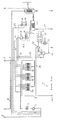
- the single figure shows a schematic representation of a process flow diagram an exhaust air purification system according to the invention.
- the exhaust air purification system 1 shown in the figure has a Abluftansaugung 2 on, in the loaded with solvent exhaust gases, for example.
- a blower 3 In one the blower 3 downstream cooler 4, the exhaust gases can be cooled.
- the fan 3 are a plurality of activated carbon containing adsorber 5a, 5b and 5c connected in parallel.
- the adsorber 5a operates in the illustration of the figure in Adsorptions réelle, in which adsorbs the solvent from the exhaust air stream become.
- the thus purified exhaust gas stream via a line 6 a Exhaust chimney 7 are supplied, from which the purified air into the atmosphere is discharged, or via a line 8, for example, in the enclosure of a Printing press are returned.
- Adsorber 5a is adsorbed the solvent loaded so that after a certain period of operation a Regeneration of the activated carbon is required.
- the desorption step 9 live steam from a steam source via a line 10 passed through the adsorber 5b.
- the activated carbon is heated and it forms a water vapor-solvent mixture (desorbate), which via a line 11 of a first cooling stage with a heat exchanger 12 (desorbate heat exchanger) is supplied.
- a heat exchanger 12 desorbate heat exchanger
- the Desorbatffyleyer 12 is the desorbate heat energy withdrawn, so that, for example, water or another suitable heating or cooling medium in the Desorbattage (2004) of 60 ° C is heated up to 95 ° C.
- drying and cooling step is supplied to the adsorber 5 c by the blower 3 unpurified exhaust gas.
- the heated by the desorption step and loaded with water vapor Adsorber 5c is thereby cooled and dried.
- About a line 13 is the in the adsorber 5c heated and humidified exhaust gas of a second cooling stage 14 forwarded.
- the second cooling stage 14 has a first discharge cooler 15, the example. With Recooling water is operated, and a downstream, the second Extract cooler 16, which is operated with cold water. In the second Cooling stage 14 condenses most of the moisture contained in the exhaust gas and is fed to a separator 17. The thus dried and cooled Exhaust gas is via a line 18 in front of the blower 3 with the main exhaust gas stream mixed from the exhaust air intake 2 and through the adsorber or the adsorber 5a passed in the adsorption mode.
- the desorbate cooled in the first cooling stage 12 (desorbate heat exchanger) is fed to a condenser 19 and an aftercooler 20, which also is connected to the separator 17.
- a condenser 19 and an aftercooler 20 In the separator 17 is solvent deposited in the liquid phase and can be discharged via a line 21 become.
- the water vapor condensate is from the separator 17 a Stripper 22 forwarded for further purification.
- the capacitor 19 and the Aftercooler 20 is connected via a breathing line 23 to the suction side of the blower 3 connected.
- the Desorbatffyleyer 12 is via a first circuit (primary circuit) 24 is connected to a buffer tank 25, which is discontinuous, i. always When an activated carbon adsorbent 5b is regenerated in the desorption step Heating or cooling medium is supplied.
- the heat energy is stored and continuously via a second circuit (secondary circuit) 26, if necessary by means of a pump 27, a temperature rectifier 28 supplied.
- This temperature rectifier 28 is a heat exchanger, in which via a line 29 live steam the steam source 10 is introduced, so that in the second circuit 26th circulating heating or cooling medium, for example. Water, continuously to a constant temperature level of, for example, about 95 ° C is raised.
- a chilled water generator 30 passed, which as a chiller by means of Heat energy of circulating in the second circuit 26 heating or cooling medium in a cold water circuit 31, a cooling medium, such as water, cools.
- Heating or cooling medium in the second circuit 26 through a heat exchanger 32 passed back into the buffer tank 25.
- the heat exchanger 32nd It serves the waste heat utilization contained in the heating or cooling medium Thermal energy. This heat energy can, for example, for heating rooms, Buildings or the like. Can be used.
- the chiller 30 is via the circuit 31 with the second discharge cooler 16 of the second cooling stage 14 connected. That in the chiller 30, for example, from 12 ° C to about 6 ° C cooled water is thus directly for the cooling of the exhaust gas of an adsorber 5c in the drying and Cooling step used. In this way can be contained in the desorbate Use heat particularly economically.
- the adsorbers in Regeneration operation after the desorption step in the drying and Cooling step deprived of moisture and the adsorber are cooled. It is therefore not required, the exhaust gases used for drying or cooling For example, on the chimney 7 to let off into the environment, but they can after being cleaned in an adsorber 5a in the adsorption mode in the enclosure of a printing machine or the like. Be returned.
- the cooling medium cooled in the cold water production plant 30 may possibly also be used for other cooling purposes in the system.
- Operating costs can be reduced by about 50%.
- the Temperature rectifier 28 live steam is used, which in the exhaust air purification system 1 already for the regeneration of the activated carbon adsorber 5a, 5b and 5c are the additional investment costs for the plant low for cold water production.
Landscapes
- Engineering & Computer Science (AREA)
- Chemical & Material Sciences (AREA)
- General Engineering & Computer Science (AREA)
- Analytical Chemistry (AREA)
- Physics & Mathematics (AREA)
- Health & Medical Sciences (AREA)
- Biomedical Technology (AREA)
- Environmental & Geological Engineering (AREA)
- Thermal Sciences (AREA)
- Mechanical Engineering (AREA)
- General Chemical & Material Sciences (AREA)
- Oil, Petroleum & Natural Gas (AREA)
- Chemical Kinetics & Catalysis (AREA)
- Treating Waste Gases (AREA)
- Organic Low-Molecular-Weight Compounds And Preparation Thereof (AREA)
- Separation Of Gases By Adsorption (AREA)
Applications Claiming Priority (2)
| Application Number | Priority Date | Filing Date | Title |
|---|---|---|---|
| DE10338410 | 2003-08-18 | ||
| DE10338410A DE10338410A1 (de) | 2003-08-18 | 2003-08-18 | Verfahren und Anlage zur Kaltwassererzeugung mittels Desorbatwärme |
Publications (2)
| Publication Number | Publication Date |
|---|---|
| EP1508360A2 true EP1508360A2 (fr) | 2005-02-23 |
| EP1508360A3 EP1508360A3 (fr) | 2005-04-13 |
Family
ID=34042225
Family Applications (1)
| Application Number | Title | Priority Date | Filing Date |
|---|---|---|---|
| EP04013305A Withdrawn EP1508360A3 (fr) | 2003-08-18 | 2004-06-05 | Procédé et appareillage pour la production d'eau froide |
Country Status (2)
| Country | Link |
|---|---|
| EP (1) | EP1508360A3 (fr) |
| DE (1) | DE10338410A1 (fr) |
Cited By (1)
| Publication number | Priority date | Publication date | Assignee | Title |
|---|---|---|---|---|
| CN104329934A (zh) * | 2014-11-21 | 2015-02-04 | 柳州市永和彩印包装有限公司 | 环保节能烘干器 |
Families Citing this family (1)
| Publication number | Priority date | Publication date | Assignee | Title |
|---|---|---|---|---|
| CN100504275C (zh) * | 2007-04-29 | 2009-06-24 | 绍兴东方能源工程技术有限公司 | 印染行业废水热能回收方法及回收系统 |
Family Cites Families (3)
| Publication number | Priority date | Publication date | Assignee | Title |
|---|---|---|---|---|
| FR2524338A1 (fr) * | 1982-04-02 | 1983-10-07 | Peabody France | Dispositif pour realiser notamment des economies d'energie dans la recuperation des charbons actifs contenant des solvants adsorbes |
| JPS59162922A (ja) * | 1983-03-08 | 1984-09-13 | Toyobo Co Ltd | 吸着装置の排熱回収方法 |
| US4589890A (en) * | 1985-01-10 | 1986-05-20 | Dedert Corporation | Heat recovery method and apparatus |
-
2003
- 2003-08-18 DE DE10338410A patent/DE10338410A1/de not_active Withdrawn
-
2004
- 2004-06-05 EP EP04013305A patent/EP1508360A3/fr not_active Withdrawn
Cited By (1)
| Publication number | Priority date | Publication date | Assignee | Title |
|---|---|---|---|---|
| CN104329934A (zh) * | 2014-11-21 | 2015-02-04 | 柳州市永和彩印包装有限公司 | 环保节能烘干器 |
Also Published As
| Publication number | Publication date |
|---|---|
| DE10338410A1 (de) | 2005-04-14 |
| EP1508360A3 (fr) | 2005-04-13 |
Similar Documents
| Publication | Publication Date | Title |
|---|---|---|
| EP0944423B1 (fr) | Procede et dispositifs pour l'epuration et la reutilisation d'air evacue renfermant des additifs (par exemple, des solvants) ou des impuretes | |
| DE3016406C2 (de) | Mehrstufiges thermisches Stofftrennverfahren mit kombiniertem Brüdenverdichter und Wärmetransformator zur Rückgewinnung der in den Brüden enthaltenden Wärme und Vorrichtung zur Durchführung des Verfahrens | |
| DE60019019T2 (de) | Verfahren und Vorrichtung zur Luftzerlegung mit Gasturbinen | |
| EP2382028B1 (fr) | Procédéde séparation du dioxyde de carbone contenu dans un gaz d'échappement d'une centrale électrique à combustible fossile | |
| EP2552568B1 (fr) | Procédé et dispositif de séparation de dioxyde de carbone des gaz d'échappement d'une centrale électrique à combustible fossile | |
| DE69525034T2 (de) | Wärmezurückgewinnung in einem Druckwechseladsorptionsverfahren | |
| DE69804799T2 (de) | Flüssigkeitsgekühlte hochdruck abscheidung für luftkreislauf-klimaanlage | |
| DE2631444A1 (de) | Verfahren und vorrichtung zur entfernung und rueckgewinnung von schwefeldioxid aus abgasen | |
| WO2014000882A2 (fr) | Procédé et dispositif de production d'une énergie électrique | |
| EP1913238A2 (fr) | Procede pour augmenter le rendement d'une centrale thermique a gaz et a vapeur combinee, comprenant un systeme de gazeification de combustible integre | |
| EP3104956B1 (fr) | Dispositif et procédé de séparation du dioxyde de carbone d'un flux de gaz, en particulier d'un flux de gaz de combustion, comprenant un circuit d'eau de refroidissement | |
| DE2951557A1 (de) | Mehrstufige verdampferanlage mit integriertem waermerueckfuehrsystem | |
| EP3132840B1 (fr) | Procédé et dispositif de séparation de substances toxiques gazeuses d'un flux gazeux | |
| DE102009022298A1 (de) | Verbesserung der Energieeffizienz eines chemischen CO2 Abscheidungsprozesses | |
| EP1508360A2 (fr) | Procédé et appareillage pour la production d'eau froide | |
| EP2551477A1 (fr) | Procédé et centrale à énergie fossile destinée à la récupération d'un condensat | |
| DE10338418B4 (de) | Verfahren und Anlage zur Abgasreinigung | |
| DE2714967C3 (de) | Verfahren zur Gewinnung von Ammoniak und schwerem Wasser | |
| EP0491339B1 (fr) | Procédé et dispositif de récupération de solvants | |
| EP0033849A2 (fr) | Procédé de récupération d'énergie thermique renfermée dans les concentrats des évaporateurs à effet multiple utilisés dans les procédés d'échange de masse thermique, et dispositif pour la mise en oeuvre du procédé | |
| EP0155578B1 (fr) | Procédé et dispositif de rectification et/ou de strippage | |
| AT528334B1 (de) | Vorrichtung zur Rückgewinnung der Wärme aus mindestens zwei unterschiedlichen Dampfströmen, Anlage, Verwendung und Verfahren | |
| BE1030432B1 (de) | Vorrichtung und Verfahren zur Abtrennung von bei der Klinkerherstellung erzeugtem Kohlendioxid | |
| EP4721839A1 (fr) | Procédé et installation de séparation de dioxyde de carbone | |
| WO2023025385A1 (fr) | Dépôt de co2 à basse température à partir de gaz d'échappement |
Legal Events
| Date | Code | Title | Description |
|---|---|---|---|
| PUAI | Public reference made under article 153(3) epc to a published international application that has entered the european phase |
Free format text: ORIGINAL CODE: 0009012 |
|
| AK | Designated contracting states |
Kind code of ref document: A2 Designated state(s): AT BE BG CH CY CZ DE DK EE ES FI FR GB GR HU IE IT LI LU MC NL PL PT RO SE SI SK TR |
|
| AX | Request for extension of the european patent |
Extension state: AL HR LT LV MK |
|
| PUAL | Search report despatched |
Free format text: ORIGINAL CODE: 0009013 |
|
| AK | Designated contracting states |
Kind code of ref document: A3 Designated state(s): AT BE BG CH CY CZ DE DK EE ES FI FR GB GR HU IE IT LI LU MC NL PL PT RO SE SI SK TR |
|
| AX | Request for extension of the european patent |
Extension state: AL HR LT LV MK |
|
| AKX | Designation fees paid | ||
| STAA | Information on the status of an ep patent application or granted ep patent |
Free format text: STATUS: THE APPLICATION IS DEEMED TO BE WITHDRAWN |
|
| 18D | Application deemed to be withdrawn |
Effective date: 20050702 |
|
| REG | Reference to a national code |
Ref country code: DE Ref legal event code: 8566 |