EP1508411A2 - Dispositif de coupe - Google Patents
Dispositif de coupe Download PDFInfo
- Publication number
- EP1508411A2 EP1508411A2 EP04018985A EP04018985A EP1508411A2 EP 1508411 A2 EP1508411 A2 EP 1508411A2 EP 04018985 A EP04018985 A EP 04018985A EP 04018985 A EP04018985 A EP 04018985A EP 1508411 A2 EP1508411 A2 EP 1508411A2
- Authority
- EP
- European Patent Office
- Prior art keywords
- cutting device
- guide
- knife
- base body
- stop
- Prior art date
- Legal status (The legal status is an assumption and is not a legal conclusion. Google has not performed a legal analysis and makes no representation as to the accuracy of the status listed.)
- Withdrawn
Links
- 238000005520 cutting process Methods 0.000 title claims abstract description 94
- 238000003825 pressing Methods 0.000 claims abstract description 26
- 238000000465 moulding Methods 0.000 claims description 17
- 239000000463 material Substances 0.000 claims description 15
- 230000001681 protective effect Effects 0.000 claims description 13
- 230000007704 transition Effects 0.000 claims description 5
- 230000006835 compression Effects 0.000 claims description 4
- 238000007906 compression Methods 0.000 claims description 4
- 239000004033 plastic Substances 0.000 claims description 4
- 229920003023 plastic Polymers 0.000 claims description 4
- 238000005452 bending Methods 0.000 claims description 3
- 238000003780 insertion Methods 0.000 claims description 3
- 230000037431 insertion Effects 0.000 claims description 3
- 229920000049 Carbon (fiber) Polymers 0.000 claims description 2
- 229920002430 Fibre-reinforced plastic Polymers 0.000 claims description 2
- 239000004917 carbon fiber Substances 0.000 claims description 2
- 239000011151 fibre-reinforced plastic Substances 0.000 claims description 2
- 239000003365 glass fiber Substances 0.000 claims description 2
- 238000009434 installation Methods 0.000 claims description 2
- 230000007246 mechanism Effects 0.000 claims description 2
- VNWKTOKETHGBQD-UHFFFAOYSA-N methane Chemical compound C VNWKTOKETHGBQD-UHFFFAOYSA-N 0.000 claims description 2
- 230000000694 effects Effects 0.000 claims 1
- 238000004146 energy storage Methods 0.000 claims 1
- 230000000284 resting effect Effects 0.000 abstract description 3
- VREFGVBLTWBCJP-UHFFFAOYSA-N alprazolam Chemical group C12=CC(Cl)=CC=C2N2C(C)=NN=C2CN=C1C1=CC=CC=C1 VREFGVBLTWBCJP-UHFFFAOYSA-N 0.000 description 5
- 238000003860 storage Methods 0.000 description 5
- 230000008901 benefit Effects 0.000 description 4
- 238000013461 design Methods 0.000 description 4
- 238000011161 development Methods 0.000 description 4
- 238000004519 manufacturing process Methods 0.000 description 4
- 239000000123 paper Substances 0.000 description 4
- 238000004026 adhesive bonding Methods 0.000 description 2
- 238000013459 approach Methods 0.000 description 2
- 238000010276 construction Methods 0.000 description 2
- 238000012423 maintenance Methods 0.000 description 2
- 230000009467 reduction Effects 0.000 description 2
- 238000003466 welding Methods 0.000 description 2
- 208000027418 Wounds and injury Diseases 0.000 description 1
- 230000009471 action Effects 0.000 description 1
- 230000000712 assembly Effects 0.000 description 1
- 238000000429 assembly Methods 0.000 description 1
- 239000011324 bead Substances 0.000 description 1
- 239000011111 cardboard Substances 0.000 description 1
- 150000001875 compounds Chemical class 0.000 description 1
- 230000006378 damage Effects 0.000 description 1
- 230000001419 dependent effect Effects 0.000 description 1
- 239000010408 film Substances 0.000 description 1
- 208000014674 injury Diseases 0.000 description 1
- 230000003993 interaction Effects 0.000 description 1
- 238000012432 intermediate storage Methods 0.000 description 1
- 238000005304 joining Methods 0.000 description 1
- 238000005461 lubrication Methods 0.000 description 1
- 239000002184 metal Substances 0.000 description 1
- 238000011022 operating instruction Methods 0.000 description 1
- 238000004806 packaging method and process Methods 0.000 description 1
- 239000002985 plastic film Substances 0.000 description 1
- 229920006255 plastic film Polymers 0.000 description 1
- 238000002360 preparation method Methods 0.000 description 1
- 230000003252 repetitive effect Effects 0.000 description 1
- 239000007787 solid Substances 0.000 description 1
Images





Classifications
-
- B—PERFORMING OPERATIONS; TRANSPORTING
- B26—HAND CUTTING TOOLS; CUTTING; SEVERING
- B26D—CUTTING; DETAILS COMMON TO MACHINES FOR PERFORATING, PUNCHING, CUTTING-OUT, STAMPING-OUT OR SEVERING
- B26D7/00—Details of apparatus for cutting, cutting-out, stamping-out, punching, perforating, or severing by means other than cutting
- B26D7/01—Means for holding or positioning work
- B26D7/015—Means for holding or positioning work for sheet material or piles of sheets
-
- B—PERFORMING OPERATIONS; TRANSPORTING
- B26—HAND CUTTING TOOLS; CUTTING; SEVERING
- B26D—CUTTING; DETAILS COMMON TO MACHINES FOR PERFORATING, PUNCHING, CUTTING-OUT, STAMPING-OUT OR SEVERING
- B26D1/00—Cutting through work characterised by the nature or movement of the cutting member or particular materials not otherwise provided for; Apparatus or machines therefor; Cutting members therefor
- B26D1/01—Cutting through work characterised by the nature or movement of the cutting member or particular materials not otherwise provided for; Apparatus or machines therefor; Cutting members therefor involving a cutting member which does not travel with the work
- B26D1/12—Cutting through work characterised by the nature or movement of the cutting member or particular materials not otherwise provided for; Apparatus or machines therefor; Cutting members therefor involving a cutting member which does not travel with the work having a cutting member moving about an axis
- B26D1/25—Cutting through work characterised by the nature or movement of the cutting member or particular materials not otherwise provided for; Apparatus or machines therefor; Cutting members therefor involving a cutting member which does not travel with the work having a cutting member moving about an axis with a non-circular cutting member
- B26D1/26—Cutting through work characterised by the nature or movement of the cutting member or particular materials not otherwise provided for; Apparatus or machines therefor; Cutting members therefor involving a cutting member which does not travel with the work having a cutting member moving about an axis with a non-circular cutting member moving about an axis substantially perpendicular to the line of cut
- B26D1/30—Cutting through work characterised by the nature or movement of the cutting member or particular materials not otherwise provided for; Apparatus or machines therefor; Cutting members therefor involving a cutting member which does not travel with the work having a cutting member moving about an axis with a non-circular cutting member moving about an axis substantially perpendicular to the line of cut with limited pivotal movement to effect cut
-
- B—PERFORMING OPERATIONS; TRANSPORTING
- B26—HAND CUTTING TOOLS; CUTTING; SEVERING
- B26D—CUTTING; DETAILS COMMON TO MACHINES FOR PERFORATING, PUNCHING, CUTTING-OUT, STAMPING-OUT OR SEVERING
- B26D7/00—Details of apparatus for cutting, cutting-out, stamping-out, punching, perforating, or severing by means other than cutting
- B26D7/01—Means for holding or positioning work
- B26D7/02—Means for holding or positioning work with clamping means
- B26D7/025—Means for holding or positioning work with clamping means acting upon planar surfaces
-
- B—PERFORMING OPERATIONS; TRANSPORTING
- B26—HAND CUTTING TOOLS; CUTTING; SEVERING
- B26D—CUTTING; DETAILS COMMON TO MACHINES FOR PERFORATING, PUNCHING, CUTTING-OUT, STAMPING-OUT OR SEVERING
- B26D7/00—Details of apparatus for cutting, cutting-out, stamping-out, punching, perforating, or severing by means other than cutting
- B26D7/22—Safety devices specially adapted for cutting machines
-
- B—PERFORMING OPERATIONS; TRANSPORTING
- B26—HAND CUTTING TOOLS; CUTTING; SEVERING
- B26D—CUTTING; DETAILS COMMON TO MACHINES FOR PERFORATING, PUNCHING, CUTTING-OUT, STAMPING-OUT OR SEVERING
- B26D7/00—Details of apparatus for cutting, cutting-out, stamping-out, punching, perforating, or severing by means other than cutting
- B26D2007/0012—Details, accessories or auxiliary or special operations not otherwise provided for
- B26D2007/0087—Details, accessories or auxiliary or special operations not otherwise provided for for use on a desktop
Definitions
- the invention relates to a cutting device, in particular a Lever cutter, for cutting leaf or sheet-like material, such as paper, Plastic films, films, cardboard, photos and the like Materials to give these materials a desired format give.
- a cutting device in particular a Lever cutter, for cutting leaf or sheet-like material, such as paper, Plastic films, films, cardboard, photos and the like Materials to give these materials a desired format give.
- Cutting devices of this type are those skilled in the various versions known. she usually consist of the function groups Main body / cutting table, knife, cuttings stop, Pressing unit and protective unit.
- a lever cutter is a cutting arm with a preferably provided curved curved knife, wherein the cutting arm at one end pivotally mounted on a bearing is held to the material to be cut by a Swiveling the cutting arm along one Counter knife having longitudinal edge of the cutting table tailor.
- a cutting device in particular a Lever, improve, especially in terms of Handling, the reduction of maintenance and / or Production costs plus consideration of safety relevant Characteristics.
- the new cutting device which in particular as a lever-cutting device is executed, has a one or multi-part body, at least one Side stop, knives, of which at least one is movably supported, at least one pressing unit as well at least one protection unit and stands out on the one hand characterized in that at least one component of the largest part the range of movement of the movable knife Protective protection unit, in particular their in Working position upright plate, towards the support surface of the body fold down or is arranged to be repositioned on the Anpress unit. These Plate preferably also serves to guide the movable knife between its upper and its lower end position.
- the plate is at its upper in its unfolded position Edge has a bend, creating an upper Stop for the movable knife is formed.
- hinges are arranged on the plate, the latter being attached to a above the support surface for the clippings arranged molding of the pressing unit.
- hinges are each provided with a latching mechanism with at least two locking positions, advantageously the hinges are made of plastic, preferably of a plastic with good sliding properties (self-lubrication).
- the hinges can be replaced by tabs and slots; However, a very secure latching or locking is necessary so that when the blade moves the (protective) plate remains in its desired position.
- a nose is formed on the plate, facing the handle side of the Anpress unit facing upright position in a recess of a component of the latter and in the folded position of the plate on the knife side side surface of the Anpress unit protrudes, thus also on the moving knife located in the lower end position.
- the protection unit is provided that on the handle of the movable knife a web in Direction of the plate so far protrudes that a section of the Plate is covered by this bridge, so that the plate in the Movement range of the movable knife between the Knife and the said bridge is guided, and thus a Folding down the plate with release of the movement range of the movable blade is prevented.
- connection standing push rod which in one approach the molding Arranged area and there in at least one guide is stored and guided, and the molding by means at least two connecting bolts with the push rod in Active compound is.
- said leadership consists of two guide blocks spaced apart from each other, in which essentially the two end regions of the Push rod are guided.
- the connecting bolts are with their one side each guided in one of the guide blocks and with their other end, each one by one Opening upwards in the bearing surface, each connected to a portion of the molded part.
- the molded part viewed in cross-section, is C-shaped and, aligned with its upstanding, vertically directed leg aligned with the knife-side wall of the base body, is arranged on the support surface, wherein the lower, substantially horizontal leg of Form part at the same time forms a contact surface.
- a C-shaped design preferably means that the base, that is to say the vertical section, and the two legs, which project preferably at right angles from the base, are preferably straight lines.
- one or both legs and / or the base of the "C" may be bent in sections.
- This embodiment is particularly advantageous if the lower, the contact surface of the molding forming leg is to achieve a linear contact pressure, so no surface pressure is to be performed on the cut material positioned for the cutting process.
- the knife side facing away Edge region of the contact surface with respect to the support surface pointing upwards is angled.
- the vertical aligned surface of the molding at the same time a Protective surface with respect to the movable knife.
- Another advantage is that the upper, horizontal lying Leg of the molded part at the same time a bearing / mounting surface for the arranged on the plate Hinges is.
- the substantially vertically aligned protective surface of the molded part in her handle-side end a trained from above Has recess in which provided on the plate, protruding nose extends.
- a special embodiment has the with the molding in Actually connecting push rod in her pivot bearing end portion a recess, in which an attached in a leg bolt operatively intervenes.
- the molding in which an attached in a leg bolt operatively intervenes.
- the near-end area of the pivot bearing end portion one of the upper Surface down incorporated recess provided, the has oblique transition areas.
- the opposite free end of a ramp provided, which drops towards the end of the push rod.
- a further development also provides for the leadership blocks designed essentially identical for the push rod are, considered in installation position, in the upper area a guide sleeve is provided in each one with the Push rod cooperating pressure or connecting pin is guided and each also a compression spring for the pick up guided connecting bolt.
- the guide sleeves each a concentrically arranged for bolt guidance Centering pin, a ring, each in one in the Support surface provided, not further specified Breakthrough, are positively inserted.
- the Guide blocks made of a fiber-reinforced material, eg. B. a glass fiber material or a carbon fiber material or a fiber-reinforced plastic.
- the handle side arranged in the body guide block a stop possesses, by a recess in the knife-side Passing through wall of the body. This stop limits the range of motion of the movable knife downward.
- lever-cutter with one or more of those described above Features equipped to total its functionality as well as to improve its cutting result and handling to facilitate.
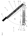
- the new cutter is in one shown in perspective view from the right. It consists of a box-shaped, preferably a so-called said sheet metal blank produced basic body 2, which also colloquially referred to as a cutting table becomes.
- the main body 2 has an overhead one Support surface 21 and two opposing Side walls 22 and 24, a front side wall 23 and a opposite knife-side wall 25, on or in which the fixed knife 6 is arranged.
- this base body is the second supported by several feet 20.
- This side stop 26 is either glued on, screwed on or otherwise firmly on attached to the support surface.
- a pivot bearing 28 for storage of the movable knife 5 is arranged.
- the cutting knife 51 this movable blade 5 is the knife-side wall 25th of the main body 2 facing on or in one Receiving part 50 and is arranged by several Fasteners 52 locked.
- the receiving part 50 is a End by means of a bearing shaft 53 in the pivot bearing 28th movably supported. Another end is on the receiving part 50th arranged a handle 54, which 54 a knife side not one further designated projecting bead, thus a Slipping the hand in the direction of the knife 51 is prevented.
- the aforementioned functional parts are also in the Figures 2 and 3 in frontal views of different Directions recognizable.
- the Support surface 21 In the area of the knife-side wall 25 is on the Support surface 21 an assembly of the pressing unit. 3 arranged.
- this is a Molded part 30, which, seen in cross-section, preferably C-shaped.
- This molding 30 is with his lower leg 31 via connecting pins 30a and 3b with one belonging to Anpress unit 3, in the main body. 2 arranged actuator operatively connected.
- the molding 30 is also in the direction Support surface 21 and opposite thereto, in one predetermined range, movable in the vertical direction supported.
- a plate 40 which leads to the protection unit 4th belongs.
- This plate 40 is preferred in the one shown Execution by means of 40 attached to selbiger Hinges 41 and 42 on the upper leg 33 of the Molded part 30 hinged folded. The folding is done preferably towards the bearing surface 21.
- edge of the plate 40 of this edge portion is directed outwardly angled, so that a stop 43 is formed, which limits the range of movement of the movable blade 5 upwards.
- a web 55 pointing in the direction of the plate 40 is arranged on the surface of the handle 54. This ensures that the plate 40 is held during the movement of the movable blade 5 from its upper position down, ie during the cutting movement, between the moving blade 51 and the web 55 and thus can not swing away or fold down, so that the safety function is maintained during the movement of the cutting blade and the movable blade 5 is guided at the same time.
- a connecting part 57 is provided, which via a leg 58 and a bolt 59 to the in Basic body 2 arranged actuating device of Pressing unit 3 attacks.
- the actuator itself and the interaction with the to the pressing unit. 3 belonging molding 30 will be explained later in detail described.
- Figures 1 to 3 is at the bottom surface 29 by a Arrow 8 indicated that on or in the bottom surface 29 of the Base body 2, a guide unit 8 is arranged, in the an additional stop 7, see Figure 2, sliding and is locked locked.
- the button 88 is part of this Guide unit 8. This guide unit 8 and the Additional stop 7 will be described later in detail.
- the bottom surface 29 of the Grundgropers 2 can be over the entire surface or be formed in sections as a surface. It is located in Frame of the invention by appropriate bending of Sections of the side walls 22 and 24 and the knife-side wall 25 and the front wall 23 the Bottom surface 29 to form; Such an embodiment is in the Figures 4a and 4b to see.
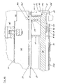
- the new cutting device 1 according to the view of Figure 3 is shown, in a sectional view, wherein the section is guided as a cross section of the side wall 24 to the side wall 22 and in the vicinity of the knife-side wall 25 across the pressure unit 3 is guided through.
- the movable blade 5 is positioned in the upper, the rest position and is guided on the plate 40.
- the provided on the bearing side end 56 connecting part 57 abuts almost on the side wall 24.
- push rod 11 is pushed by means of the connecting part 57 and the leg 58 - not visible in this sectional plane - together with the bolt 59 in the direction of the side wall 22.
- the connecting bolts 30a and 30b are each mounted and guided in a guide block 8 and 10, respectively. In these guide blocks 9 and 10 and the push rod 11 is guided and stored.
- FIGS. 4a and 4b details of the illustration shown in FIG. 4 are shown enlarged. Thus, in the figure 4a, the left and shown in Figure 4b, the right area.
- FIG. 4a shows the movable blade 5 in the upper position.
- the arranged on the receiving part 50 end 56 connecting part 57 together with legs 58 is in the position "contact pressure unit solved".
- the molded part 30 of the pressing unit 3 has a lower horizontal surface, the contact surface 31, an upstanding vertical surface, the protective surface 32, and a 32 extending from the latter, substantially horizontal surface, the bearing surface 33.
- On the bearing surface 33 they may also be titled with mounting surface, sitting part of a hinge while the other part of the same hinge with the upright plate 40 of the protection unit 4 is connected.
- the vertically movable mold part 30, in particular the contact surface 31, is connected on this side of the cutting device 1 by means of a guided through the contact surface 31 and attached to selbiger 31 bearing pin 30a with the actuator of the pressing unit 3.
- the bearing pin 30 a is guided with its middle and the subsequent other end portion in a guide sleeve 91 of the guide block 9 and held under spring pressure 93.
- the guide sleeve 91 is opened downwardly to the push rod 11, so that the respective end portion of the connecting pin 30a can come into contact with the upper surface of the push rod 11 and rests against this.
- the guide block 9 is arranged on the inside of the support surface 21, ie in the base body 2.
- a centering pin 90 in the form of a Guiding ring arranged.
- This centering pin 90 engages positively in an incorporated in the support surface 21 breakthrough and thus adjusted in position to the relevant edge.
- the guide block 9 is attached to the inside of the housing part 21 and / or the knife-side wall 25 in addition to the form-fit non-positively by screwing, gluing or welding.
- guide block 9 For precise, user-friendly and easy-to-maintain guidance are in the guide block 9, in the area of the lower one Surface, spaced apart and in a same plane arranged guide surfaces 92 and 92 'are provided.
- the push rod 11 is in the arrow "BK” and "BL” shown directions linearly movable. During the Movement becomes the one from above into a near-end section the push rod 11 recessed lowering 110, the oblique Transition areas, below the end of the Joining bolt 30a moves along. Since the Connecting bolt 30a is biased by spring force, lowers this connecting pin 30a during a movement of the Push rod 11 to the left. Which inevitably also the at the other end of the connecting bolt 30a arranged contact surface 31 of the molded part 30 is lowered is, which alsenfines on the support surface 21 and under the pressing surface 31 guided through clippings is pressed.
- FIG. 4b the right-hand region of the illustration shown in FIG. 4 is shown enlarged.
- the provided in this area guide block 10 is constructed substantially similar to the guide block 9, essentially mirror-image.
- a guide sleeve is also provided, which is similar to the guide sleeve 91 of the arranged on the other side guide block 9 and is designated here by 101.
- this guide sleeve 101 of the connecting pin 30b is guided, which also passes through the contact surface 31 on the other end of the molded part 30 and is likewise fixed by a counter element 30b 'on the molded part 30.
- a centering pin 100 is likewise provided on the guide sleeve 101, which is also of annular design and engages in a form-fitting manner in a recess provided in the bearing surface 21.
- the near-end and the end region of the push rod 11 are guided on guide surfaces 102 and 102 'of the guide block 10.
- the end region of the push rod 11 is provided with a bevel 111 which drops from above to the outer edge. Upon movement of the push rod 11 in the direction of arrow "BK" also lowers the contact surface 31 on this page.
- FIGS. 5a and 5b show, analogously, the illustrations from FIGS. 4a and 4b, but the plane of the guided cross section in these FIGS. 5a and 5b is displaced further in the direction of the front wall 23, so that the guide blocks 9 and 10 are in one uncut state are shown. Otherwise, the parts and assemblies of the cutting device 1 shown are numbered with the same reference numerals, so that can be dispensed with a repetitive description. It can also be seen from both FIGS. 5a and 5b that, in the case of the molded part 30, the lower leg directed away from the cutting edge, the contact surface 31, is angled upward in its front edge region, ie away from the support surface 21.
- FIGS. 6a and 6b portions of the Cutting device 1 shown, wherein the movable Knife 5 in its lower position, ie the working position "cut" is located.
- FIG. 6a the view of the front wall 23 from toward molding 30 of the pressing unit 3.
- the plate 40 of the protection unit 4 is in the direction Support surface 21 by pivoting in the hinges Lowered 41 and 42.
- FIG. 6b the state of the Cutting device 1 shown in Figure 6a in plan view.
- the folded plate 44 at least partially covers the Support surface 21 together with side stop 26.
- the in the plate 40th right circles above are not further specified, known fasteners for fixing a part of the hinge 41 on the plate 40.
- the handle side provided nose-shaped projection 44 of the plate 40th at least partially surmounted the knife 51 and the Pick-up part 50 of the movable knife 5. Should, against the Operating instructions and working instructions for Cutting device 1, the movable knife 5 are raised, would the web 55 of the movable blade 5 at the latest the nose 44 of the plate 40 abut, in the one shown Position limits the movement to the top.
- the additional stop 7 per se and the guide unit for this part 7 are shown in detail.
- the additional stop 7 consists of a horizontally oriented in functional position guide member 70 and on one side adjoining thereto, substantially perpendicular towering stop member 71.
- tabs 72 and 73 are bent outwardly projecting in the side regions, which are oriented horizontally parallel to the guide member 70 , At these tabs each have a leg 74 and 75 are pivotally mounted.
- the guide unit 8 is arranged on or in the bottom surface 29 of the base body 2 and designed in that the additional stop 7 can be arranged both from the knife-side wall 25 and from the front wall 23 on the base body 2 - the cutting table , For example, in FIG. 6b, the additional stop 7 is arranged on the base body 2 from the knife-side wall 25.
- the legs 74 and 75 are pivoted in this position, since the distance between the cutting edge and the stop member 71 is small.
- FIGS. 8a and 8b show details of the guide unit 8, their fixed guide parts 81 with respect to the fixed Knife 6 are aligned at right angles.
- the reference edge - are in or on the Base plate 80 and corresponding to this in parts of the Bottom surface 29 of the cutting device 1 Form gleichmaschine and Form gleichausappelgeber provided.
- the base plate 80 After production of the Form gleiches the base plate 80 also still non-positively connected to parts of the bottom surface 29, for Example by screwing, gluing or welding.
- It (8) has a base plate 80, with a narrow side 80a and an opposite second narrow side 80b and a longitudinal side 80c and an opposite second longitudinal side 80d, wherein in the region of the longitudinal side 80c fixed guide members 81 and in the region of the second longitudinal side 80d movable Guide members 82 are arranged.
- As a fixed guide members 81 at least two L-shaped tabs 81a and 81b are provided, which are arranged in the insertion direction of the stop 7 in alignment one behind the other.
- the movable guide members 82 are in the embodiment shown here, two pivotable legs 83 and 84, which are each pivotally mounted about a pivot bearing 83a and 84a in the direction of the longitudinal sides 8c and 8d and in a region close to the pivot bearings each have a guide tab 83b and 84b, wherein the latter 83b, 84b are preferably L-shaped.
- the pivotable legs 83 and 84 are each provided with a toothing 85 or 86 at their end regions facing away from the pivot bearing 83a or 84a, which mesh with one another.
- a web 83c or 84c is provided in each case at these end regions, which are arranged with their free ends at least partially overlapping, wherein these webs 83c and 84c still in the opposite one longitudinal side 80c mounted rod 87, which in the direction of the double arrow 87th 'is movable, attacks. It is also arranged on the rod 87, a force accumulator 89, which is supported on one of the longitudinal sides, in particular the longitudinal side 80c.
- the reference numerals "P1" and "P2”, the two extreme position of the pivotable legs 83 and 84 are marked. In the illustration in Figure 8a, the rod 87 is pushed by pressing the knob 88 in the direction of the opposite second longitudinal side 80d.
- the pivotable legs 83 and 84 are in the position "clamping solved", ie in the position P1.
- the guide member 70 of the auxiliary stopper 7 can be inserted without resistance in the L-shaped tabs 81a, 81b and 83b and 84b.
- the button 88 is released by the operator by the force of the spring 89 on the rod 87, the pivotable legs 83 and 84 together with the guide tab 83b and 84b arranged in them the opposite direction, ie towards the longitudinal side 80c, moves.
- the interlocking teeth 85 and 86 the movement on both guide plates 83b and 84b takes place simultaneously and uniformly.
- the stop member 71 can be applied to which Thomasgut, the cutting edge, the fixed blade 6 is aligned at right angles, since the guide member 70 of the guide plates 83b and 84b against which also with respect to the cutting edge, that fixed knife , aligned fixed guide members 81, in particular against the tabs 81 a and 81 b of the guide 8 are pressed.
Landscapes
- Life Sciences & Earth Sciences (AREA)
- Forests & Forestry (AREA)
- Engineering & Computer Science (AREA)
- Mechanical Engineering (AREA)
- Knives (AREA)
- Details Of Cutting Devices (AREA)
Applications Claiming Priority (2)
| Application Number | Priority Date | Filing Date | Title |
|---|---|---|---|
| DE20312687U DE20312687U1 (de) | 2003-08-13 | 2003-08-13 | Schneidegerät |
| DE20312687U | 2003-08-13 |
Publications (2)
| Publication Number | Publication Date |
|---|---|
| EP1508411A2 true EP1508411A2 (fr) | 2005-02-23 |
| EP1508411A3 EP1508411A3 (fr) | 2006-02-08 |
Family
ID=29285968
Family Applications (1)
| Application Number | Title | Priority Date | Filing Date |
|---|---|---|---|
| EP04018985A Withdrawn EP1508411A3 (fr) | 2003-08-13 | 2004-08-11 | Dispositif de coupe |
Country Status (2)
| Country | Link |
|---|---|
| EP (1) | EP1508411A3 (fr) |
| DE (1) | DE20312687U1 (fr) |
Cited By (1)
| Publication number | Priority date | Publication date | Assignee | Title |
|---|---|---|---|---|
| FR2917989A1 (fr) * | 2007-06-29 | 2009-01-02 | Bruno Andre Martial Mouglalis | Nouveau coupe papier destine a la restauration et le commerce en particulier pour la decoupe du talon d'angle de coupons type ticket restaurant et autres. |
Families Citing this family (2)
| Publication number | Priority date | Publication date | Assignee | Title |
|---|---|---|---|---|
| US20060162513A1 (en) * | 2005-01-21 | 2006-07-27 | General Binding Corporation | Trimmer with light guidance |
| CN113275487B (zh) * | 2021-04-14 | 2022-07-15 | 何斐瀚 | 轨枕用钢筋群组切断机 |
Citations (2)
| Publication number | Priority date | Publication date | Assignee | Title |
|---|---|---|---|---|
| US5377569A (en) * | 1993-05-07 | 1995-01-03 | Xerox Corporation | Signature booklet maker with a modified fold blade and a trim waste elimination device |
| GB2292535A (en) * | 1994-08-25 | 1996-02-28 | Chiu Liang Gan | Workpiece holding and aligning assembly |
Family Cites Families (12)
| Publication number | Priority date | Publication date | Assignee | Title |
|---|---|---|---|---|
| DE473870C (de) | 1927-03-05 | 1929-03-22 | Max Kranz | Handschneidemaschine |
| US2345450A (en) | 1943-04-21 | 1944-03-28 | Adolph I Blanc | Trimming board |
| GB1068915A (en) * | 1965-01-18 | 1967-05-17 | Doherty Sons Ltd Edward | Improvements in or relating to guillotines |
| DE1996050U (de) | 1967-04-28 | 1968-11-07 | Krug & Priester Bueromaschinen | Hebelschneidmaschine |
| DE1993934U (de) | 1968-04-26 | 1968-09-19 | Krug & Priester | Hebelschneidmaschine mit anpressbalken. |
| GB1223358A (en) * | 1968-11-27 | 1971-02-24 | James Christie & Sons Ltd | Improvements in or relating to guillotines |
| US3811355A (en) * | 1972-11-10 | 1974-05-21 | R Cole | Paper cutter guard |
| DE2723548C2 (de) * | 1977-05-25 | 1979-05-23 | Wilhelm Dahle Buero- Und Zeichengeraetefabrik, 8630 Coburg | Schnittgutniederhalter an insbesondere einem Papierschneider |
| GB1536117A (en) | 1977-08-10 | 1978-12-20 | Royal Sovereign Group Ltd | Guillotines |
| FR2460763A1 (fr) * | 1979-07-02 | 1981-01-30 | Frey Almer Ltd | Cisaille destinee a couper du papier ou des matieres analogues |
| DE29901091U1 (de) | 1999-01-22 | 2000-06-21 | Ideal-Werk Krug & Priester Gmbh & Co Kg, 72336 Balingen | Schneidgerät, insbesondere für Papier |
| DE20307241U1 (de) | 2003-05-08 | 2003-06-26 | Swedex GmbH & Co. KG, 41468 Neuss | Schneidgerät |
-
2003
- 2003-08-13 DE DE20312687U patent/DE20312687U1/de not_active Expired - Lifetime
-
2004
- 2004-08-11 EP EP04018985A patent/EP1508411A3/fr not_active Withdrawn
Patent Citations (2)
| Publication number | Priority date | Publication date | Assignee | Title |
|---|---|---|---|---|
| US5377569A (en) * | 1993-05-07 | 1995-01-03 | Xerox Corporation | Signature booklet maker with a modified fold blade and a trim waste elimination device |
| GB2292535A (en) * | 1994-08-25 | 1996-02-28 | Chiu Liang Gan | Workpiece holding and aligning assembly |
Cited By (1)
| Publication number | Priority date | Publication date | Assignee | Title |
|---|---|---|---|---|
| FR2917989A1 (fr) * | 2007-06-29 | 2009-01-02 | Bruno Andre Martial Mouglalis | Nouveau coupe papier destine a la restauration et le commerce en particulier pour la decoupe du talon d'angle de coupons type ticket restaurant et autres. |
Also Published As
| Publication number | Publication date |
|---|---|
| EP1508411A3 (fr) | 2006-02-08 |
| DE20312687U1 (de) | 2003-10-23 |
Similar Documents
| Publication | Publication Date | Title |
|---|---|---|
| DE69405655T2 (de) | Kappsäge mit Parallelogramkonstruktion | |
| DE4306312C2 (de) | Papierschneider | |
| DE69607292T2 (de) | Drucker mit Schneid- und Schutzvorrichtung | |
| DE60300416T2 (de) | Rahmenelement mit Feder für ein Werkzeug | |
| DE60202553T2 (de) | Schneidvorrichtung mit zurückziehbarer Klinge | |
| DE3714302A1 (de) | Schere | |
| DE202006009493U1 (de) | Rollenschneidgerät zum Beschneiden von Blattgut | |
| EP0593395B1 (fr) | Dispositif pour écarter un dos pinçant pour la reliure de feuilles | |
| EP0049016A1 (fr) | Dispositif de transport pour des bandes de papier dans des machines comptables | |
| EP0438736B1 (fr) | Disposif pour trancher du matériel lamellé superposé avec un refouleur à aligner | |
| EP2023774A1 (fr) | Volet de compartiment de câblage pour table | |
| DE3445744C1 (de) | Vorrichtung zum wahlweisen Anschneiden oder Abschneiden eines Papierstreifens | |
| EP0353389A1 (fr) | Massicot | |
| EP3584179B1 (fr) | Dispositif de fermeture d'un recipient au moyen d'un film de couverture | |
| EP1454695A2 (fr) | Cisaille | |
| EP0207059B1 (fr) | Dispositif de fermeture pour classeur | |
| EP1508411A2 (fr) | Dispositif de coupe | |
| DE4323393A1 (de) | Mähdrescher | |
| DE102007006339B4 (de) | Tür für einen Aktenvernichter | |
| DE2937801A1 (de) | Universal-gartenschere | |
| DE8422028U1 (de) | Presse zum nuten, ritzen, perforieren oder schneiden von pappe od. dgl. | |
| DE20321091U1 (de) | Heftvorrichtung eines Aktenordners | |
| DE8704161U1 (de) | Medizinisches, insbesondere chirurgisches Instrument | |
| DE10063809C1 (de) | Schere zum Anschneiden der Stiele von Schnittblumen | |
| DE20307241U1 (de) | Schneidgerät |
Legal Events
| Date | Code | Title | Description |
|---|---|---|---|
| PUAI | Public reference made under article 153(3) epc to a published international application that has entered the european phase |
Free format text: ORIGINAL CODE: 0009012 |
|
| AK | Designated contracting states |
Kind code of ref document: A2 Designated state(s): AT BE BG CH CY CZ DE DK EE ES FI FR GB GR HU IE IT LI LU MC NL PL PT RO SE SI SK TR |
|
| AX | Request for extension of the european patent |
Extension state: AL HR LT LV MK |
|
| PUAL | Search report despatched |
Free format text: ORIGINAL CODE: 0009013 |
|
| AK | Designated contracting states |
Kind code of ref document: A3 Designated state(s): AT BE BG CH CY CZ DE DK EE ES FI FR GB GR HU IE IT LI LU MC NL PL PT RO SE SI SK TR |
|
| AX | Request for extension of the european patent |
Extension state: AL HR LT LV MK |
|
| 17P | Request for examination filed |
Effective date: 20051220 |
|
| AKX | Designation fees paid |
Designated state(s): AT BE BG CH CY CZ DE DK EE ES FI FR GB GR HU IE IT LI LU MC NL PL PT RO SE SI SK TR |
|
| 17Q | First examination report despatched |
Effective date: 20090326 |
|
| GRAP | Despatch of communication of intention to grant a patent |
Free format text: ORIGINAL CODE: EPIDOSNIGR1 |
|
| GRAJ | Information related to disapproval of communication of intention to grant by the applicant or resumption of examination proceedings by the epo deleted |
Free format text: ORIGINAL CODE: EPIDOSDIGR1 |
|
| GRAP | Despatch of communication of intention to grant a patent |
Free format text: ORIGINAL CODE: EPIDOSNIGR1 |
|
| INTG | Intention to grant announced |
Effective date: 20170131 |
|
| INTG | Intention to grant announced |
Effective date: 20170210 |
|
| STAA | Information on the status of an ep patent application or granted ep patent |
Free format text: STATUS: THE APPLICATION IS DEEMED TO BE WITHDRAWN |
|
| 18D | Application deemed to be withdrawn |
Effective date: 20170621 |