EP1508421A2 - Hinterschäumtes Bauteil und zugehöriges Herstellungsverfahren - Google Patents
Hinterschäumtes Bauteil und zugehöriges Herstellungsverfahren Download PDFInfo
- Publication number
- EP1508421A2 EP1508421A2 EP04019107A EP04019107A EP1508421A2 EP 1508421 A2 EP1508421 A2 EP 1508421A2 EP 04019107 A EP04019107 A EP 04019107A EP 04019107 A EP04019107 A EP 04019107A EP 1508421 A2 EP1508421 A2 EP 1508421A2
- Authority
- EP
- European Patent Office
- Prior art keywords
- support frame
- component
- outer edge
- section
- fabric
- Prior art date
- Legal status (The legal status is an assumption and is not a legal conclusion. Google has not performed a legal analysis and makes no representation as to the accuracy of the status listed.)
- Withdrawn
Links
Images
Classifications
-
- B—PERFORMING OPERATIONS; TRANSPORTING
- B29—WORKING OF PLASTICS; WORKING OF SUBSTANCES IN A PLASTIC STATE IN GENERAL
- B29C—SHAPING OR JOINING OF PLASTICS; SHAPING OF MATERIAL IN A PLASTIC STATE, NOT OTHERWISE PROVIDED FOR; AFTER-TREATMENT OF THE SHAPED PRODUCTS, e.g. REPAIRING
- B29C44/00—Shaping by internal pressure generated in the material, e.g. swelling or foaming ; Producing porous or cellular expanded plastics articles
- B29C44/02—Shaping by internal pressure generated in the material, e.g. swelling or foaming ; Producing porous or cellular expanded plastics articles for articles of definite length, i.e. discrete articles
- B29C44/12—Incorporating or moulding on preformed parts, e.g. inserts or reinforcements
- B29C44/1257—Joining a preformed part and a lining, e.g. around the edges
-
- B—PERFORMING OPERATIONS; TRANSPORTING
- B29—WORKING OF PLASTICS; WORKING OF SUBSTANCES IN A PLASTIC STATE IN GENERAL
- B29C—SHAPING OR JOINING OF PLASTICS; SHAPING OF MATERIAL IN A PLASTIC STATE, NOT OTHERWISE PROVIDED FOR; AFTER-TREATMENT OF THE SHAPED PRODUCTS, e.g. REPAIRING
- B29C44/00—Shaping by internal pressure generated in the material, e.g. swelling or foaming ; Producing porous or cellular expanded plastics articles
- B29C44/02—Shaping by internal pressure generated in the material, e.g. swelling or foaming ; Producing porous or cellular expanded plastics articles for articles of definite length, i.e. discrete articles
- B29C44/12—Incorporating or moulding on preformed parts, e.g. inserts or reinforcements
- B29C44/14—Incorporating or moulding on preformed parts, e.g. inserts or reinforcements the preformed part being a lining
- B29C44/143—Means for positioning the lining in the mould
-
- B—PERFORMING OPERATIONS; TRANSPORTING
- B29—WORKING OF PLASTICS; WORKING OF SUBSTANCES IN A PLASTIC STATE IN GENERAL
- B29C—SHAPING OR JOINING OF PLASTICS; SHAPING OF MATERIAL IN A PLASTIC STATE, NOT OTHERWISE PROVIDED FOR; AFTER-TREATMENT OF THE SHAPED PRODUCTS, e.g. REPAIRING
- B29C44/00—Shaping by internal pressure generated in the material, e.g. swelling or foaming ; Producing porous or cellular expanded plastics articles
- B29C44/02—Shaping by internal pressure generated in the material, e.g. swelling or foaming ; Producing porous or cellular expanded plastics articles for articles of definite length, i.e. discrete articles
- B29C44/12—Incorporating or moulding on preformed parts, e.g. inserts or reinforcements
- B29C44/14—Incorporating or moulding on preformed parts, e.g. inserts or reinforcements the preformed part being a lining
- B29C44/16—Incorporating or moulding on preformed parts, e.g. inserts or reinforcements the preformed part being a lining shaped by the expansion of the material
Definitions
- the present invention relates to a foam-backed component and a method for producing a foam-backed Component, in particular an interior trim part of a motor vehicle.
- Foamed components have an outer skin, which consists of a Fabric web section is formed, as well as a foam filling.
- the outer skin can basically be closed and extend over the entire surface of the component. As well If the component can be open on one or more sides, so that the outer skin does not cover the entire surface of the component extends.
- a foam-backed Component as a trim part, in particular for Interior trim in a motor vehicle, to be used.
- trim parts must be connected to a corresponding Support structure can be attached to the desired cladding train.
- the fabric section can basically made of any material and basically designed with any surface structure be, whereby the outer skin visible in the respective application of the component designed according to aesthetic considerations can be.
- the foam filling tensions the outer skin and can be designed in particular energy-absorbing.
- From DE 43 16 536 A1 discloses a method for producing a Such foam-backed component known in the in a lower mold half first a cover layer material sprayed after hardening the finished part forms an outer skin of the component. On the cover layer is then filled a foamable material. While closing the shape of the top layer is sheared off at its edge, wherein the remaining edge before foaming the filled Material is bent inwards. The bonding between the bent cover layer and one on the upper mold half attached carrier part is carried out with the aid of the foaming Material.
- the cost of producing a mold, that shear off the outer edge of the cover, inside Bend and harden until the foamed material can position in the desired manner is relative large.
- the present invention deals with the problem an improved for a method of the type mentioned Specify an embodiment, in particular an inexpensive Production of foam-backed components allows.
- the invention is based on the general idea that the Shell of the finished component forming fabric section to be attached to a support frame before foaming. By Foaming will make this support frame an integral one Component of the component. Furthermore, according to the invention manufactured component on an inside the supporting frame attached outer edge of the fabric section inside the component, that is, the outer edge of the panel section is embedded in the foam and not visible. This approach has the advantage that a post-processing, especially a clean cut of superior Edges, not required for the component according to the invention is.
- the fabric section be placed on the inside of the support frame, that the outer edge of the fabric section over the outer edge the support frame protrudes, in which case the fabric section at its outer edge before foaming flush with Outside edge of the support frame is cut.
- Another embodiment is characterized in that the support frame is recessed in the component, whereby the outside of the support frame flush with a back completes the component.
- the sunken arrangement of the support frame in the component is the degree of integration for the Support frame increased at least visually.
- the support frame can also on the Rear of the component at its inner edge of the foam and bordered at its outer edge of the fabric section be.
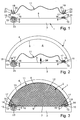
- FIGS. 1 to 3 is a mold 1 for the production a foam-backed component 2 (see Fig. 3) in several parts, expediently two-part, constructed. Accordingly possesses the mold 1 here a lower part 3 and an upper part 4.
- the two halves (lower part 3 and upper part 4) of Forming tool 1 define an inner contour 5 of the mold 1. With closed mold 1, this inner contour forms 5 of the halves 3, 4 according to FIGS. 2 and 3 a cavity 6 of the mold 1.
- This support frame 8 can be formed in one piece or multiple parts. It is preferred an embodiment in which the support frame 8 as a closed Ring is configured.
- the support frame 8 serves the finished component 2 on a supporting structure, not shown here to install.
- the component 2 with Help the support frame 8 on a body panel to be veneered a motor vehicle are mounted.
- the support frame 8 with one or more fasteners 9 be equipped in principle can have any structure.
- it acts it is in the fasteners 9 to a threaded opening or a threaded bolt or - as here - by one mushroom-shaped pin of a clip connection. Is appropriate the respective fastening element 9 in one piece on the support frame 8 trained.
- the finished component 2 has a fabric section 11.
- This fabric section 11 forms to the support frame 8 a Outer skin of the component 2.
- the outer skin or the fabric web section 11 is with a foam body 12 and with a Foam filling 12 foamed, the interior of the component. 2 forms. Since the foam filling 12 on the by a viewer the outer skin side facing away, so behind the outer skin is located, the fabric section 11 is backfoamed.
- Fig. 3 is shown in the preferred embodiment shown here the component 2 is formed so that the support frame. 8 sunk in the foam body 12 is arranged. Accordingly includes an outer side 13 of the support frame 8 flush with the back 7 of the component 2 from. Furthermore, the Support frame 8 within the back 7 with respect to an edge region 14 of the component 2 is arranged offset inwards. In this way, the support frame 8 is at its the web section 11 facing outer edge 15 of the fabric web section 11 bordered and facing away from it on the fabric section 11 Inner edge 16 of the foam or the foam body 12th bordered.
- the finished component 2 has by this configuration a shape integrated support frame 8 with an aesthetic advantageous transition between in the installed state a viewer facing the outside 10 and the built-in Condition not visible to the viewer 7.
- the inventive method for producing the foam-backed Part 2 works as follows:
- the fabric web section 11 is initially on the support frame 8 attached.
- the fabric section 11 is to advance has been tailored and will be in the field an outer edge 17 on an inner side 18 of the support frame eighth hung up.
- a corresponding Tool 19 can be used for this purpose - as indicated here - a corresponding Tool 19 can be used.
- this inner side 18 faces away from the outer side 13.
- an inside can be used which connects to the outside 13.
- the cut of the Fabric section 11 is usually dimensioned so that its outer edge 17 on the outer edge 15 of the support frame 8 protrudes when the outer edge 17 placed on the inside 18 is.
- the fabric section 11 on the support frame. 8 may be appropriate provided a welded joint.
- the fabric section 11 as the support frame 8 consist of a thermoplastic material. hereby can be a particularly durable cohesive connection made between the panel section 11 and the support frame 8 become.
- the tool 19 comprises a Welding tool 20, with the help of the welding process can be carried out.
- fabric section 11 and support frame 8 by ultrasonic welding together get connected.
- other attachment methods possible, for example gluing.
- this is Tool 19 and the welding tool 20 in addition to a Cutting tool 21 equipped with the help of an over the outer edge 15 of the support frame 8 protruding remainder 22 of the Outside edges 17 can be cut off, so that the fabric section 11 thereafter at its outer edge 17 flush with the outer edge 15 of the support frame 8 is cut.
- This Cutting process can during the welding process or after the Welding process to be performed. It is also possible to carry out the cutting process before the welding process, provided the tool 19 the outer edge 17 sufficiently firmly against the inside can press 18.
- the welding and cutting are so on each other Voted that the two processes in a single Operation can be performed. This can increases the clock frequency for the production of the component 2 become.
- the support frame 8 - as here - a fastener 9, which protrudes beyond the outer side 13 of the support frame 8, is the lower part 3 of the mold 1 with a corresponding Recess 23 provided, in which the fastener 9 protrudes, while the support frame 8 with its outside 13 incidentally on the inner contour 5 of the lower part. 3 is applied.
- Fig. 2 shows the state which after welding and after Cutting the outer edge 17 is present. Furthermore, in Fig. 2, the mold 1 already closed. No later than now the support frame 8 is arranged in the mold 1, that its outer side 13 flat on the inner contour 5 of a Tool half 3 or 4 is present.
- the cut of the fabric section 11 so to the inner contour 5 of the tool halves 3, 4 is adapted to the subsequent foaming process the fabric web section 11 without wrinkling on the inner contour 5 can create.
- the fabric section 11 is now filled with foam, which is symbolized by an arrow 24.
- the foaming is doing of the later back 7 of the finished Component 2 ago, quasi performed by the support frame 8 through.
- the pressure building up tightens the body Fabric web section 11 and places itself on the contours of the inner contour 5 of the mold 1 at. Since the fabric section 11 is attached to the support frame 8 so that its outer edge 17th is flush with the outer edge 15 of the support frame 8, results from the foaming along the inside 18th the support frame 8 a double layer for the fabric section 11th
- a negative pressure in particular a more or less strong vacuum formed in the mold 1 be such that the fabric section 11 at the inner contour 5 of the mold 1 more or less contour right invests.
- the choice of material for the fabric section 11 can for one carried out with regard to an intended decorative effect become. On the other hand is a sufficient elasticity to take into account so that the fabric section 11 during foaming the inner contour 5 can lay out completely, apart from the open back 7.
- the foam for the Foam body 12 is suitably chosen so that it by the mold 1 form given shape of the back-foamed component 2 can sustain. This can be a Hard foam or to act on a soft foam.
- the foam body 12 is produced from a plastic, in particular from a thermoplastic, e.g. polyurethane, preferably however, expanded polypropylene (EPP). Especially it is possible to select the foam so that the component 2 can develop a shock absorbing effect. This is especially in interior trim parts for motor vehicles advantageous.
- the component 2 After curing of the foam body 12, the component 2 are removed from the mold 1. A post-processing of the back-foamed component 2 is no longer necessary. All in all thus results in a comparatively simple feasible Manufacturing process, which is a cheap manufacture of the component 2 allows.
Landscapes
- Casting Or Compression Moulding Of Plastics Or The Like (AREA)
- Vehicle Interior And Exterior Ornaments, Soundproofing, And Insulation (AREA)
Abstract
Description
- Fig. 1 bis 3
- Querschnitte durch stark vereinfachte Prinzipdarstellungen eines Formwerkzeugs bei unterschiedlichen Phasen des erfindungsgemäßen Herstellungsverfahrens.
Claims (23)
- Verfahren zur Herstellung eines hinterschäumten Bauteils (2), insbesondere eines Innenraumverkleidungsteils eines Kraftfahrzeugs,bei dem ein Stoffbahnabschnitt (11), der beim fertigen Bauteil (2) eine Außenhaut des Bauteils (2) bildet, an einer Innenseite (18) eines Tragrahmens (8) befestigt wird, der beim fertigen Bauteil (2) mit einer Außenseite (13) zur Anbringung des Bauteils (2) an einer Tragstruktur dient,bei dem in einem Formwerkzeug (1), dessen Innenkontur (5) einen Hohlraum (6) ausbildet und in dem der Tragrahmen (8) mit an der Innenkontur (5) anliegender Außenseite (13) angeordnet ist, der Stoffbahnabschnitt (11) so ausgeschäumt wird, dass der Stoffbahnabschnitt (11) an der Innenkontur (5) zur Anlage kommt.
- Verfahren nach Anspruch 1,
dadurch gekennzeichnet, dass der Stoffbahnabschnitt (11) zur Befestigung an der Innenseite (18) des Tragrahmens (8) darauf aufgelegt und damit verschweißt wird. - Verfahren nach Anspruch 1 oder 2,
dadurch gekennzeichnet, dass der Stoffbahnabschnitt (11) und/oder der Tragrahmen (8) aus einem thermoplastischen Kunststoff besteht/bestehen. - Verfahren nach einem der Ansprüche 1 bis 3,
dadurch gekennzeichnet,dass der Stoffbahnabschnitt (11) so an der Innenseite (18) des Tragrahmens (8) angeordnet wird, dass ein Außenrand (17) des Stoffbahnabschnitts (11) über eine Außenkante (15) des Tragrahmens (8) übersteht,dass der Stoffbahnabschnitt (11) an seinem Außenrand (17) vor dem Ausschäumen bündig zur Außenkante (15) des Tragrahmens (8) geschnitten wird. - Verfahren nach Anspruch 4,
dadurch gekennzeichnet, dass das Anschweißen des Stoffbahnabschnitts (11) am Tragrahmen (8) und das Schneiden des Außenrands (17) des Stoffbahnabschnitts (11) in einem gemeinsamen Arbeitsgang durchgeführt wird. - Verfahren nach Anspruch 4 oder 5,
dadurch gekennzeichnet, dass in ein Schweißwerkzeug (20), das zum Anschweißen des Stoffbahnabschnitts (11) an den Tragrahmen (8) dient, ein Schneidwerkzeug (21) integriert ist, das zum Schneiden des Außenrands (17) des Stoffbahnabschnitts (11) dient. - Verfahren nach einem der Ansprüche 1 bis 6,
dadurch gekennzeichnet, dass der Stoffbahnabschnitt (11) so an der Innenseite (18) des Tragrahmens (8) befestigt ist, dass ein Außenrand (17) des Stoffbahnabschnitts (11) entlang einer Außenkante (15) des Tragrahmens (8) verläuft. - Verfahren nach einem der Ansprüche 1 bis 7,
dadurch gekennzeichnet, dass der Stoffbahnabschnitt (11) an der Innenseite (18) des Tragrahmens (8) eine Doppellage bildet. - Verfahren nach einem der Ansprüche 1 bis 8,
dadurch gekennzeichnet, dass der Tragrahmen (8) im Bauteil (2) versenkt angeordnet ist, so dass die Außenseite (13) des Tragrahmens (8) flächenbündig mit einer Rückseite (7) des Bauteils (2) abschließt. - Verfahren nach Anspruch 9,
dadurch gekennzeichnet, dass der Tragrahmen (8) an der Rückseite (7) des Bauteils (2) an seiner Innenkante (16) vom Schaumstoff und an seiner Außenkante (15) vom Stoffbahnabschnitt (11) eingefaßt ist. - Verfahren nach einem der Ansprüche 1 bis 10,
dadurch gekennzeichnet,dass der Tragrahmen (8) an seiner Außenseite (13) wenigstens ein Befestigungselement (9) aufweist, das über die Außenseite (13) vorsteht,dass das Formwerkzeug (1) an seiner Innenkontur (5) für jedes Befestigungselement (9) eine geeignete Aussparung (23) aufweist, in die das Befestigungselement (9) beim Ausschäumen hineinragt. - Verfahren nach einem der Ansprüche 1 bis 11,
dadurch gekennzeichnet, dass der Tragrahmen (8) als geschlossener Ring ausgestaltet ist. - Hinterschäumtes Bauteil, insbesondere Innenraumverkleidungsteil eines Kraftfahrzeugs, mit einem Stoffbahnabschnitt (11), der einen Schaumkörper (12) an einer Vorderseite (10) des Bauteils (2) umhüllt und an einer Innenseite (18) eines Tragrahmens (8) befestigt ist, der an einer Rückseite (7) des Bauteils (2) angeordnet ist und mit einer Außenseite (13) zur Anbindung des Bauteils (2) an einer Tragstruktur ausgebildet ist.
- Bauteil nach Anspruch 13,
dadurch gekennzeichnet, dass der Stoffbahnabschnitt (11) an der Innenseite (18) des Tragrahmens (8) angeschweißt ist. - Bauteil nach Anspruch 13 oder 14,
dadurch gekennzeichnet, dass der Stoffbahnabschnitt (11) und/oder der Tragrahmen (8) aus einem thermoplastischen Kunststoff besteht/bestehen. - Bauteil nach einem der Ansprüche 13 bis 15,
dadurch gekennzeichnet, dass der Stoffbahnabschnitt (11) so an der Innenseite (18) des Tragrahmens (8) angeordnet ist, dass ein Außenrand (17) des Stoffbahnabschnitts (11) bündig zu einer Außenkante (15) des Tragrahmens (8) verläuft. - Bauteil nach einem Ansprüche 13 bis 16,
dadurch gekennzeichnet, dass der Stoffbahnabschnitt (11) so an der Innenseite (18) des Tragrahmens (8) befestigt ist, dass ein Außenrand (17) des Stoffbahnabschnitts (11) entlang einer Außenkante (15) des Tragrahmens (8) verläuft. - Bauteil nach einem der Ansprüche 13 bis 17,
dadurch gekennzeichnet, dass der Stoffbahnabschnitt (11) an der Innenseite (18) des Tragrahmens (8) eine Doppellage bildet. - Bauteil nach einem der Ansprüche 13 bis 18,
dadurch gekennzeichnet, dass der Tragrahmen (8) im Bauteil (2) versenkt angeordnet ist, so dass die Außenseite (13) des Tragrahmens (8) flächenbündig mit der Rückseite (7) des Bauteils (2) abschließt. - Bauteil nach Anspruch 19,
dadurch gekennzeichnet, dass der Tragrahmen (8) an der Rückseite (7) des Bauteils (2) an seiner Innenkante (16) vom Schaumkörper (12) und an seiner Außenkante (15) vom Stoffbahnabschnitt (11) einfasst ist. - Bauteil nach einem der Ansprüche 13 bis 20,
dadurch gekennzeichnet, dass der Tragrahmen (8) an seiner Außenseite (13) wenigstens ein Befestigungselement (9) aufweist, das über die Außenseite (13) vorsteht. - Bauteil nach Anspruch 21,
dadurch gekennzeichnet, dass das Befestigungselement (9) einstückig am Tragrahmen (8) ausgebildet ist. - Bauteil nach einem der Ansprüche 13 bis 22,
dadurch gekennzeichnet, dass der Tragrahmen (8) als geschlossener Ring ausgestaltet ist.
Applications Claiming Priority (2)
| Application Number | Priority Date | Filing Date | Title |
|---|---|---|---|
| DE10338812 | 2003-08-21 | ||
| DE2003138812 DE10338812B4 (de) | 2003-08-21 | 2003-08-21 | Hintergeschäumtes Bauteil und zugehöriges Herstellungsverfahren |
Publications (3)
| Publication Number | Publication Date |
|---|---|
| EP1508421A2 true EP1508421A2 (de) | 2005-02-23 |
| EP1508421A8 EP1508421A8 (de) | 2005-05-18 |
| EP1508421A3 EP1508421A3 (de) | 2006-04-19 |
Family
ID=34042251
Family Applications (1)
| Application Number | Title | Priority Date | Filing Date |
|---|---|---|---|
| EP04019107A Withdrawn EP1508421A3 (de) | 2003-08-21 | 2004-08-12 | Hinterschäumtes Bauteil und zugehöriges Herstellungsverfahren |
Country Status (2)
| Country | Link |
|---|---|
| EP (1) | EP1508421A3 (de) |
| DE (1) | DE10338812B4 (de) |
Cited By (2)
| Publication number | Priority date | Publication date | Assignee | Title |
|---|---|---|---|---|
| CN112372924A (zh) * | 2020-10-14 | 2021-02-19 | 东风汽车集团有限公司 | 一种发泡夹层结构的制孔方法 |
| CN118456884A (zh) * | 2024-05-30 | 2024-08-09 | 奇瑞汽车股份有限公司 | 一种汽车内饰abc柱低压注塑软包边缘反包工装及方法 |
Family Cites Families (11)
| Publication number | Priority date | Publication date | Assignee | Title |
|---|---|---|---|---|
| US4555141A (en) * | 1983-08-05 | 1985-11-26 | Tachikawa Spring Co. Ltd. | Vehicle seat |
| DE3614481A1 (de) * | 1986-04-29 | 1987-11-05 | Wolfgang Zipperle | Sonnenblende fuer kraftfahrzeuge und verfahren zum herstellen derselben |
| AU591830B1 (en) * | 1988-02-23 | 1989-12-14 | Tachi-S Co., Ltd. | Method of making integrally foam-molded seats |
| FR2627426A1 (fr) * | 1988-02-23 | 1989-08-25 | Tachi S Co | Procede de fabrication de sieges moules integralement en mousse |
| DE4105261C2 (de) * | 1991-02-20 | 1994-03-31 | Lignotock Gmbh | Verfahren zum Kaschieren von räumlich verformten Trägerteilen |
| DE4305200C2 (de) * | 1993-02-19 | 1999-01-07 | Lignotock Gmbh | Innenverkleidungsteil und Verfahren zu seiner Herstellung |
| DE4316536A1 (de) * | 1993-05-18 | 1994-11-24 | Elastogran Gmbh | Verfahren und Vorrichtung zur Herstellung von Fahrzeuginnenverkleidungen o. dgl. aus Mehrkomponenten-Kunststoffen |
| JP2991321B2 (ja) * | 1994-04-15 | 1999-12-20 | 株式会社イノアックコーポレーション | 表皮付き発泡体を表面に有するプラスチック成形品およびその製造方法 |
| DE19827362A1 (de) * | 1998-06-19 | 1999-12-23 | Reichenecker Hans Storopack | Aufgeschäumtes Formteil |
| DE10024814A1 (de) * | 2000-05-19 | 2001-11-22 | Bayerische Motoren Werke Ag | Herstellverfahren für ein Kunststoff-Sandwichbauteil |
| DE10151367B4 (de) * | 2001-10-17 | 2007-11-08 | Faurecia Innenraum Systeme Gmbh | Innenverkleidungsteil für Kraftfahrzeuge |
-
2003
- 2003-08-21 DE DE2003138812 patent/DE10338812B4/de not_active Expired - Fee Related
-
2004
- 2004-08-12 EP EP04019107A patent/EP1508421A3/de not_active Withdrawn
Cited By (2)
| Publication number | Priority date | Publication date | Assignee | Title |
|---|---|---|---|---|
| CN112372924A (zh) * | 2020-10-14 | 2021-02-19 | 东风汽车集团有限公司 | 一种发泡夹层结构的制孔方法 |
| CN118456884A (zh) * | 2024-05-30 | 2024-08-09 | 奇瑞汽车股份有限公司 | 一种汽车内饰abc柱低压注塑软包边缘反包工装及方法 |
Also Published As
| Publication number | Publication date |
|---|---|
| EP1508421A8 (de) | 2005-05-18 |
| EP1508421A3 (de) | 2006-04-19 |
| DE10338812A1 (de) | 2005-03-31 |
| DE10338812B4 (de) | 2012-05-31 |
Similar Documents
| Publication | Publication Date | Title |
|---|---|---|
| DE19929971B4 (de) | Kraftfahrzeugtür-Innenverkleidung | |
| DE69203615T2 (de) | Verfahren zur Herstellung einer Fahrzeugtür, insbesondere für ein Automobil; Unter-Einheit zur Anwendung des Verfahrens und Tür welche durch die Anwendung des Verfahrens erhalten wird. | |
| DE102011050003A1 (de) | Gelochtes Kunststoff-Formteil mit Dekormaterial sowie Vorrichtung und Verfahren zu dessen Herstellung | |
| DE10158401A1 (de) | Moduldach für ein Kraftfahrzeug und Verfahren zu seiner Montage | |
| DE10207705A1 (de) | Gegossene, nahtlose Fahrzeuginnenverkleidung zum Verbergen eines Airbags | |
| DE102004062331B4 (de) | Hitzeschild und Verfahren zu dessen Herstellung | |
| DE3880731T2 (de) | Vorgeformtes innenausstattungselement fuer kraftfahrzeuge und dessen herstellungsverfahren. | |
| EP1747977A1 (de) | Verfahren zum Herstellen eines geschäumten Bauteils und Schäumwerkzeug zur Anwendung dieses Verfahrens | |
| WO2011088995A1 (de) | Verfahren zur herstellung eines innenverkleidungsteils | |
| EP2070680B1 (de) | Verfahren und Vorrichtung zur Herstellung eines Formteils mit mehreren aneinandergrenzenden, unterschiedlichen Dekorbereichen | |
| EP0571640B1 (de) | Akustisch wirksame Wandverkleidung für Kraftfahrzeuge | |
| DE10338812B4 (de) | Hintergeschäumtes Bauteil und zugehöriges Herstellungsverfahren | |
| DE2944797C2 (de) | Verfahren zum Herstellen eines gekrümmten Leistenabschnitts | |
| EP2424718B1 (de) | Vorrichtung zur herstellung eines kunststoff-formteils | |
| DE602004002051T2 (de) | Verschweisste anordnung eines sichtteils mit einem anderen teil eineskraftfahrzeugs und verfahren | |
| DE10346730B4 (de) | Verfahren zum Herstellen eines Innenraum-Verkleidungsteiles eines Fahrzeuges | |
| DE102005033051B4 (de) | Verfahren zur Herstellung eines Dekorbauteils und Vorrichtung zur Durchführung dieses Verfahrens | |
| EP1591318B1 (de) | Verfahren zum Herstellen eines Innenverkleidungsteils und Innenverkleidungsteil | |
| DE102005011076A1 (de) | Fahrzeugtür, Fahrzeugrahmen und Verfahren zu ihrer Herstellung | |
| DE102013018655A1 (de) | Verfahren zur Herstellung eines Verkleidungsbauteils und Verkleidungsbauteil | |
| EP3047948B1 (de) | Belederungsmodell | |
| EP2091770B1 (de) | Austattungsteil, insbesondere für ein kraftfahrzeug, mit einem ersten teilbereich und einem einstückig mittels eines verbindungungsbereichs angebundenen zweiten teilbereich | |
| DE19716409A1 (de) | Flächiges Auskleidungselement, insbesondere Kraftfahrzeug-Innenverkleidungselement | |
| DE202013005670U1 (de) | Verkrallung eines Randstreifens | |
| DE202005021105U1 (de) | Dekorbauteil für ein Kraftfahrzeug und Vorrichtung zur Herstellung des Dekorbauteils |
Legal Events
| Date | Code | Title | Description |
|---|---|---|---|
| PUAI | Public reference made under article 153(3) epc to a published international application that has entered the european phase |
Free format text: ORIGINAL CODE: 0009012 |
|
| AK | Designated contracting states |
Kind code of ref document: A2 Designated state(s): AT BE BG CH CY CZ DE DK EE ES FI FR GB GR HU IE IT LI LU MC NL PL PT RO SE SI SK TR |
|
| AX | Request for extension of the european patent |
Extension state: AL HR LT LV MK |
|
| RAP1 | Party data changed (applicant data changed or rights of an application transferred) |
Owner name: TARACELL R. MEIERS SOEHNE AG Owner name: DAIMLERCHRYSLER AG |
|
| RIC1 | Information provided on ipc code assigned before grant |
Ipc: B29C 44/14 19950101ALI20051205BHEP Ipc: B29C 44/12 19950101ALI20051205BHEP Ipc: B29C 44/16 19950101AFI20041221BHEP |
|
| PUAL | Search report despatched |
Free format text: ORIGINAL CODE: 0009013 |
|
| AK | Designated contracting states |
Kind code of ref document: A3 Designated state(s): AT BE BG CH CY CZ DE DK EE ES FI FR GB GR HU IE IT LI LU MC NL PL PT RO SE SI SK TR |
|
| AX | Request for extension of the european patent |
Extension state: AL HR LT LV MK |
|
| AKX | Designation fees paid | ||
| RAP1 | Party data changed (applicant data changed or rights of an application transferred) |
Owner name: TARACELL R. MEIERS SOEHNE AG Owner name: DAIMLERCHRYSLER AG |
|
| REG | Reference to a national code |
Ref country code: DE Ref legal event code: 8566 |
|
| STAA | Information on the status of an ep patent application or granted ep patent |
Free format text: STATUS: THE APPLICATION IS DEEMED TO BE WITHDRAWN |
|
| 18D | Application deemed to be withdrawn |
Effective date: 20061020 |