EP1508422A1 - Verfahren zur kontinuierlichen Herstellung von Polyurethan-Blockschaum - Google Patents
Verfahren zur kontinuierlichen Herstellung von Polyurethan-Blockschaum Download PDFInfo
- Publication number
- EP1508422A1 EP1508422A1 EP04103077A EP04103077A EP1508422A1 EP 1508422 A1 EP1508422 A1 EP 1508422A1 EP 04103077 A EP04103077 A EP 04103077A EP 04103077 A EP04103077 A EP 04103077A EP 1508422 A1 EP1508422 A1 EP 1508422A1
- Authority
- EP
- European Patent Office
- Prior art keywords
- reaction mixture
- trough
- rising
- reaction mixtures
- foam
- Prior art date
- Legal status (The legal status is an assumption and is not a legal conclusion. Google has not performed a legal analysis and makes no representation as to the accuracy of the status listed.)
- Withdrawn
Links
Images


Classifications
-
- B—PERFORMING OPERATIONS; TRANSPORTING
- B29—WORKING OF PLASTICS; WORKING OF SUBSTANCES IN A PLASTIC STATE IN GENERAL
- B29C—SHAPING OR JOINING OF PLASTICS; SHAPING OF MATERIAL IN A PLASTIC STATE, NOT OTHERWISE PROVIDED FOR; AFTER-TREATMENT OF THE SHAPED PRODUCTS, e.g. REPAIRING
- B29C44/00—Shaping by internal pressure generated in the material, e.g. swelling or foaming ; Producing porous or cellular expanded plastics articles
- B29C44/34—Auxiliary operations
- B29C44/36—Feeding the material to be shaped
- B29C44/46—Feeding the material to be shaped into an open space or onto moving surfaces, i.e. to make articles of indefinite length
- B29C44/468—Feeding the material to be shaped into an open space or onto moving surfaces, i.e. to make articles of indefinite length in a plurality of parallel streams which unite during the foaming
-
- B—PERFORMING OPERATIONS; TRANSPORTING
- B29—WORKING OF PLASTICS; WORKING OF SUBSTANCES IN A PLASTIC STATE IN GENERAL
- B29C—SHAPING OR JOINING OF PLASTICS; SHAPING OF MATERIAL IN A PLASTIC STATE, NOT OTHERWISE PROVIDED FOR; AFTER-TREATMENT OF THE SHAPED PRODUCTS, e.g. REPAIRING
- B29C44/00—Shaping by internal pressure generated in the material, e.g. swelling or foaming ; Producing porous or cellular expanded plastics articles
- B29C44/20—Shaping by internal pressure generated in the material, e.g. swelling or foaming ; Producing porous or cellular expanded plastics articles for articles of indefinite length
- B29C44/22—Shaping by internal pressure generated in the material, e.g. swelling or foaming ; Producing porous or cellular expanded plastics articles for articles of indefinite length consisting of at least two parts of chemically or physically different materials, e.g. having different densities
-
- B—PERFORMING OPERATIONS; TRANSPORTING
- B29—WORKING OF PLASTICS; WORKING OF SUBSTANCES IN A PLASTIC STATE IN GENERAL
- B29C—SHAPING OR JOINING OF PLASTICS; SHAPING OF MATERIAL IN A PLASTIC STATE, NOT OTHERWISE PROVIDED FOR; AFTER-TREATMENT OF THE SHAPED PRODUCTS, e.g. REPAIRING
- B29C44/00—Shaping by internal pressure generated in the material, e.g. swelling or foaming ; Producing porous or cellular expanded plastics articles
- B29C44/34—Auxiliary operations
- B29C44/36—Feeding the material to be shaped
- B29C44/46—Feeding the material to be shaped into an open space or onto moving surfaces, i.e. to make articles of indefinite length
- B29C44/461—Feeding the material to be shaped into an open space or onto moving surfaces, i.e. to make articles of indefinite length dispensing apparatus, e.g. dispensing foaming resin over the whole width of the moving surface
- B29C44/462—Feeding the material to be shaped into an open space or onto moving surfaces, i.e. to make articles of indefinite length dispensing apparatus, e.g. dispensing foaming resin over the whole width of the moving surface provided with pre-foaming devices
Definitions
- the present invention relates to a process for the continuous manufacture of polyurethane foam blocks as defined in the preamble of claim 1.
- Maxfoam process An example of such a process is the so-called Maxfoam process.
- the foamable polyurethane reaction mixture is fed into the bottom of a trough where it slowly begins to react.
- the reacting mass flows over the forward edge of the trough onto a bottom paper, which is sliding at a constant velocity on an inclined fall plate.
- the fall plate is made up of different sections hinged together at pivot points. The angle of each fall-plate section can be adjusted to match the rise profile of the foam formulation. In this way, a flat-topped block can be achieved showing either a flat or a slightly domed top surface.
- the produced foam blocks are destined to be cut into different kinds of foam parts, in particular into complete mattresses or foam parts or layers for mattresses or seats.
- a drawback of the known process is that the mattresses cut out of such foam blocks are of a uniform composition.
- a mattress has to show however zones with different properties.
- the mattress can for example be a three-zone mattress or even a five-zone mattress comprising two end zones (head and feet zones), a middle zone (lumbar area) and two zones (pelvis zone and shoulder zone) separating the middle zone from the end zones.
- the two end zones and the middle zones should be softer than the two zones separating them.
- a three or a five zone mattress can be produced by gluing foam parts of different properties (cut from different slabstock foam blocks) together. However, it appears to be quite difficult to glue these foam parts together without seams. Moreover, such a gluing process is labour intensive and has thus an important effect on the cost price of the mattress.
- US-A-4 073 839 discloses a process for moulding mattresses having zones of varying hardness by pouring, by means of multiple pour heads, different foamable polyurethane reaction mixtures in one and the same mould. According to this US patent, the problem of the known processes was that the zones of different density were erratic and that the interfaces between the zones were difficult to control. To solve this problem, US-A-4 073 839 proposes to spray the different foamable reaction mixtures in a fan-like planular pattern and to adjust those patterns to control the area of overlap between the different zones. According to US-A-4 073 839 such a process can not only be used for moulding mattresses in individual moulds but the foamable reaction mixtures could also be applied onto a moving slab belt. However, US-A-4 073 839 does not teach to produce foam blocks having a height higher than 0.7 m but only teaches to produce mattresses which have, in practice, a considerably smaller height or thickness, in particular smaller than 20 cm.
- An object of the present invention is therefore to provide a new process for the continuous manufacture of polyurethane foam blocks which enables to manufacture foam blocks having zones produced of different foamable reaction mixtures and wherein the interfaces between the different zones are sufficiently vertical in particular to cut uniform multi-zone mattresses out of the foam block.
- the trough of the continuous foaming machine is divided by at least one partition wall in at least two through sections.
- a different foamable reaction mixture is introduced so that the produced foam blocks are composed of portions made of a different polyurethane foam.
- the volumes of neighbouring trough sections should more particularly be adjusted in such a manner that the rising reaction mixtures have risen to heights which differ less than 2 cm, preferably less than 1 cm, from each other, when leaving the neighbouring trough sections.
- the rise profiles of the reaction mixtures introduced in the neighbouring trough sections should be so similar that, when rising further to 70% of the average height reached by the rising reaction mixtures, any difference between the average heights of the neighbouring rising reaction mixtures should be smaller than 5 cm and preferably smaller than 3 cm, the height difference being determined assuming a vertical interface between the rising reaction mixtures. In order to achieve an interface between two adjacent foam portions which is as vertical as possible, the differences between the heights of the rising reaction mixtures should be reduced as much as possible.
- the present invention also relates to a process for manufacturing multi-zone mattresses, which is characterised in that the mattresses are cut in a transverse direction out of a polyurethane foam block manufactured in accordance with the process according to the invention.
- the present invention moreover relates to a foam block obtainable by the process according to the invention and to a mattress cut out of such a foam block.
- the invention relates to a process for the continuous manufacture of polyurethane foam blocks 1 which comprise, seen in cross-section, portions produced of different foamable polyurethane reaction mixtures.
- polyurethane foam blocks 1 which comprise, seen in cross-section, portions produced of different foamable polyurethane reaction mixtures.
- multi-zone mattresses having two or more zones of a different polyurethane foam material can be cut directly out of such blocks, more particularly in the transverse direction thereof.
- a problem with the manufacture of such blocks is that the interfaces between the different foam portions or zones should be as vertical as possible so that uniform mattresses can be produced, i.e. mattresses which are all almost the same.
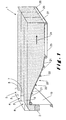
- FIG. 1 illustrates schematically the principles of a Maxfoam machine which has been adjusted to function in accordance with the process according to the invention.
- the foaming machine comprises a trough 2 which has been divided by means of two partition walls 3 into three trough sections, namely a first or middlemost trough section 4 and a second 5 and a third trough section 6 each on an opposite side of the first trough section 4.
- a first 7, a second 8 and respectively a third foamable polyurethane reaction mixture 9 is introduced in the bottom of each of the different trough sections.
- the first reaction mixture 7, fed in the first trough section 4 is different from the second and the third reaction mixtures.
- the second and the third reaction mixtures may however be the same so that symmetrical multi-zone mattresses can be cut out of the foam block.
- the first foamable reaction mixture is prepared in a first mixing head 10 which has a polyol component feed line 11 and an isocyanate component feed line 12 and is connected with a pipe 13 to the first trough section 1.
- the second and third reaction mixtures (which are the same in this example) are prepared in a second mixing head 14 which has a polyol component feed line 15 and an isocyanate component feed line 16 and is connected with pipes 17 and 18 to the second 5 and the third trough sections 6.
- the reaction mixtures arriving underneath in the trough sections are liquid and remain in the trough sections at least until they start to rise to produce a foam.
- the rising reactions mixtures 7, 8, 9 flow subsequently over the forward edges of the trough sections onto a bottom sheet 19.
- This bottom sheet 19 slides downward over a fall plate 20 made up of four to seven sections 21 which are hinged together at pivot points 22.
- the pivot points 22 can be lowered or raised to change the configuration of the fall-plate sections 21 to match the rise profile of the foamable reaction mixtures.
- the foam which has been produced thereon arrives on a conveyer 23 transporting the foam, at a predetermined velocity v, in a direction 24 to a cutting unit (not illustrated).
- the thus produced blocks 1 are usually substantially rectangular and have a width W larger than 1 m, in particular larger than 1.5 m and a height larger than 0.7 m.
- the width W is for example equal to 2 or 2.1 m so that it is possible to cut mattresses having a length of 1.9 m, 2 m or optionally 2.1 m in the transverse direction out of these blocks.
- the width W of the block may vary somewhat over the height of the mattress, in which case the average width W should be larger than the above indicated limits.
- the length of the blocks is greater than 5 m, and may in practice even reach 50 or 60 m.
- the portion 25 produced from the first reaction mixture 7 has an average width W 1
- the portion 26 produced from the second reaction mixture 8 an average width w 2
- the portion 27 produced from the third reaction mixture 8 an average width w 3 .
- the different portions of the foam block have further respectively a density D 1 , D 2 and D 3 . These densities may be different or the same. If they are the same, the foams produced from the different reaction mixtures may differ in colour, hardness or other physical or chemical properties.
- rise profile For each reaction mixture a rise profile is established.
- the second and the third reaction mixtures 8, 9 are identical, only two rise profiles have to be established.
- These rise profiles indicate the rise height of the foamable reaction mixture (expressed as a percentage of the total rise) as a function of the time after the mixing of the reaction components.
- the first part of the graph is the so-called “cream time”, i.e. the time between the mixing of the foam ingredients and the beginning of the foam rise.
- the second part of the graph is then the so-called "rise time”.
- Figure 8 illustrates the rise profiles of two reaction mixtures which have a very similar rise profile so that they can be used together in the process according to the invention
- Figure 9 illustrates the rise profiles of two reaction mixtures which are so different that they cannot be used together in the process according to the invention.
- the volumes V 1 , V 2 and V 3 of the different trough sections are selected in such a manner that, when leaving the trough sections and coming into contact with one another, the neighbouring reaction mixtures have risen to respectively a first average height (h 1 ) and a second average height (h 2 ), which differ less than 2 cm, preferably less than 1 cm, from one another.
- the volumes V 1 , V 2 , V 3 , V 4 and V 5 of the different trough sections are selected in such a manner that the differences between the heights of the reaction mixtures which come into contact with one another upon leaving the trough sections, namely the differences between h 1 and h 2 , h 1 and h 3 , h 2 and h 4 , and h 3 and h 5 , are smaller than 2 cm and preferably smaller than 1 cm. If the height of one rising reaction mixture is not large enough, the volume of the corresponding trough section should be increased.
- these reaction mixtures are formulated to have such a rise profile, that when rising further to at least 70% of said average height (H), any difference between the average heights of the neighbouring rising reaction mixtures, determined in a direction perpendicular to the travelling direction 24 of the foam and assuming a vertical interface between the rising reaction mixtures, is smaller than 5 cm and preferably even smaller than 3 cm.
- Figure 9 illustrates the rise profiles of reaction mixtures which cannot be used together in the process according to the invention. Indeed, when the slowest rising reaction mixture has risen to 70% of its total rise height, the fastest reaction mixture has already risen to about 98% of its total rise height. Even for a block having only a height of 70 cm, this corresponds to a difference of about 19 cm. For the reaction mixtures having the rise profiles illustrated in Figure 8, the differences between these rise profiles are so small that, even when making higher foam block, the actual difference in rise height is always smaller than 5 cm, and in particular smaller than 3 cm.
- the partition walls may be situated entirely within the trough or may extend, as illustrated in Figures 1 and 2, from the trough over a short distance above the fall plate.
- the partition wall or walls 3 in the trough 2 preferably separate the rising reaction mixtures at least until they have risen to 1 %, preferably to 2% and more preferably to 3% of their total rise height. However, they preferably separate the rising reaction mixtures at the most until they have risen to 20%, preferably to 15% and more preferably to 10% of their total rise height. This can be determined easily by determining the time the reaction mixtures need to flow from the mix heads 10, 14 to the end of the partition walls 3 and to determine on the rise profiles the extent to which they have already risen at that time (percentage of their total rise height).
- the process according to the invention enables to produce large foam blocks comprising two or more longitudinal portions made of a different polyurethane foam. These blocks are in particular suited to cut entire mattresses out of these blocks. These mattresses may in particular be three or five zoned mattresses.
- Figure 6 illustrates a cross-section of a foam block for producing five zone mattresses.
- the first 25, the fourth 28 and the fifth foam portions 29 are preferably made of a first foamable polyurethane reaction mixture whilst the second 26 and the third foam portions 27 are preferably made of a second foamable polyurethane reaction mixture.
- the first reaction mixture is preferably formulated to produce a polyurethane foam which is softer than the polyurethane foam produced from the second reaction mixture.
- interface lines i.e. the lines between the different foam regions seen in different cross-sections of the foam blocks
- These interface lines 30 may be straight or curved. If they are curved, a linear line 31 can be drawn through the respective interface line 30 so that the surface area 32 between the interface line 30 and this linear line 31 is minimised. In practice, this can be done easily by a linear regression analysis.
- the process according to the invention enables to manufacture foam blocks wherein the straight interface lines 30 and/or the linear lines 31 drawn through the curved interface lines, form an angle ( ⁇ ) of between 80° and 90°, in particular between 85° and 90°, with the bottom surface of the block.
- the interface between the different foam regions can be controlled in such a manner that, in the cross-sectional areas of the foam block between a height of 0.05 * H and a height of 0.95*H measured from the bottom surface of the block, the interface lines 30 are either straight in different cross-sections of the block or are curved, in which case any distance between the interface line 30 and said linear line 31, measured in a direction parallel to the bottom surface of the block is smaller than 5 cm and preferably smaller than 3 cm.
Landscapes
- Casting Or Compression Moulding Of Plastics Or The Like (AREA)
- Mattresses And Other Support Structures For Chairs And Beds (AREA)
Applications Claiming Priority (2)
| Application Number | Priority Date | Filing Date | Title |
|---|---|---|---|
| NL1023916A NL1023916C2 (nl) | 2003-07-14 | 2003-07-14 | Werkwijze voor het vervaardigen van een kunststof schuimlichaam, inrichting voor het vervaardigen van kunststof schuimlichamen, alsmede een schuimlichaam. |
| NL1023916 | 2003-07-14 |
Publications (1)
| Publication Number | Publication Date |
|---|---|
| EP1508422A1 true EP1508422A1 (de) | 2005-02-23 |
Family
ID=34056988
Family Applications (1)
| Application Number | Title | Priority Date | Filing Date |
|---|---|---|---|
| EP04103077A Withdrawn EP1508422A1 (de) | 2003-07-14 | 2004-06-30 | Verfahren zur kontinuierlichen Herstellung von Polyurethan-Blockschaum |
Country Status (2)
| Country | Link |
|---|---|
| EP (1) | EP1508422A1 (de) |
| NL (1) | NL1023916C2 (de) |
Cited By (3)
| Publication number | Priority date | Publication date | Assignee | Title |
|---|---|---|---|---|
| CN110982030A (zh) * | 2019-11-26 | 2020-04-10 | 沈阳鲜众聚氨酯有限公司 | 一种一步法制备轻质聚氨酯半硬泡的连续生产方法 |
| KR20200045285A (ko) * | 2018-10-22 | 2020-05-04 | (주) 디유티코리아 | 폴리우레탄의 스트랜드 발포체의 연속 제조장치 |
| EP3680082A4 (de) * | 2017-09-08 | 2021-08-11 | Dut Korea Co., Ltd | Verfahren zur herstellung einer schaumstoffmatratze mit mehreren härtegraden und mehreren elastizitätsgraden durch prozess des kontinuierlichen aufschäumens und damit hergestellte schaumstoffmatratze |
Citations (3)
| Publication number | Priority date | Publication date | Assignee | Title |
|---|---|---|---|---|
| US3786122A (en) * | 1970-09-01 | 1974-01-15 | Unifoam Ag | Method for the continuous production of a foamed polyurethane slab involving flow from a vessel over a weir structure |
| US4073839A (en) * | 1976-04-19 | 1978-02-14 | The Goodyear Tire & Rubber Company | Method of zone pouring foam products |
| ES2138904A1 (es) * | 1997-05-28 | 2000-01-16 | Betere Fab Lucia Antonio | Procedimiento de moldeado de colchones para uso personalizado de los mismos. |
Family Cites Families (2)
| Publication number | Priority date | Publication date | Assignee | Title |
|---|---|---|---|---|
| DE2631145C2 (de) * | 1976-07-10 | 1981-09-24 | Bayer Ag, 5090 Leverkusen | Verfahren und Vorrichtung zum Auftragen einer Schicht eines flüssigen, schäumfähigen Reaktionsgemisches auf eine kontinuierlich geförderte Unterlage |
| NL1017380C2 (nl) * | 2001-02-16 | 2002-08-19 | Corus Technology B V | Werkwijze en inrichting voor het produceren van een sandwichpaneel, en aldus vervaardigd sandwichpaneel. |
-
2003
- 2003-07-14 NL NL1023916A patent/NL1023916C2/nl not_active IP Right Cessation
-
2004
- 2004-06-30 EP EP04103077A patent/EP1508422A1/de not_active Withdrawn
Patent Citations (3)
| Publication number | Priority date | Publication date | Assignee | Title |
|---|---|---|---|---|
| US3786122A (en) * | 1970-09-01 | 1974-01-15 | Unifoam Ag | Method for the continuous production of a foamed polyurethane slab involving flow from a vessel over a weir structure |
| US4073839A (en) * | 1976-04-19 | 1978-02-14 | The Goodyear Tire & Rubber Company | Method of zone pouring foam products |
| ES2138904A1 (es) * | 1997-05-28 | 2000-01-16 | Betere Fab Lucia Antonio | Procedimiento de moldeado de colchones para uso personalizado de los mismos. |
Cited By (3)
| Publication number | Priority date | Publication date | Assignee | Title |
|---|---|---|---|---|
| EP3680082A4 (de) * | 2017-09-08 | 2021-08-11 | Dut Korea Co., Ltd | Verfahren zur herstellung einer schaumstoffmatratze mit mehreren härtegraden und mehreren elastizitätsgraden durch prozess des kontinuierlichen aufschäumens und damit hergestellte schaumstoffmatratze |
| KR20200045285A (ko) * | 2018-10-22 | 2020-05-04 | (주) 디유티코리아 | 폴리우레탄의 스트랜드 발포체의 연속 제조장치 |
| CN110982030A (zh) * | 2019-11-26 | 2020-04-10 | 沈阳鲜众聚氨酯有限公司 | 一种一步法制备轻质聚氨酯半硬泡的连续生产方法 |
Also Published As
| Publication number | Publication date |
|---|---|
| NL1023916C2 (nl) | 2005-01-17 |
Similar Documents
| Publication | Publication Date | Title |
|---|---|---|
| US4073839A (en) | Method of zone pouring foam products | |
| EP2051818B1 (de) | Vorrichtung zum aufbringen eines viskosen gemisches auf eine fläche sowie verfahren zur herstellung eines isolationselements | |
| EP2167295B1 (de) | Verfahren und vorrichtung zur herstellung von platten mit melier-wirkung | |
| US4216181A (en) | Process for applying a layer of a liquid foamable reaction mixture to a continuously moving shaping support | |
| US8177541B2 (en) | Gypsum board forming device with improved slurry spread | |
| PL77832B1 (en) | Method for the continuous production of a foamed polyurethane slab involving flow from a vessel over a weir structure[us3786122a] | |
| JPH07164454A (ja) | ポリウレタンスラブストック発泡体の連続製造用の方法およびその装置 | |
| US3325573A (en) | Manufacture of foam material | |
| US4255105A (en) | Equipment for the continuous production of foam boards | |
| US4986744A (en) | Apparatus for manufacturing multi-layered concrete roof tiles | |
| NZ199749A (en) | Forming polyurethane foam;foam moves upwards between upwardly moving webs | |
| US8100680B2 (en) | Apparatus for manufacturing floor mat using double conveyor system | |
| CA1160011A (en) | Method and apparatus for the preparation of foamed structures | |
| JPH0811140A (ja) | フォーム材ブロックもしくはフォーム材ウェブを連続製造するための方法および装置 | |
| US3812227A (en) | Method of producing a flat top slab of foamed polyurethane | |
| EP0472574B1 (de) | Verfahren zur herstellung geschäumter gegenstände mit bereichen verschiedener härte | |
| US3887670A (en) | Apparatus for and method of producing continuous foamed plastic bunstock | |
| US4005958A (en) | Apparatus for continuous production of rectangular cross-sectioned foamed plastic bunstock | |
| US4128611A (en) | Continuous process and apparatus for producing foamed polymer bunstock having a substantially rectangular cross-section | |
| US20080145544A1 (en) | Method and Device for Producing Polyurethane Foam Slab Stock | |
| JP2001505834A (ja) | 多層フォーム製品の製造法 | |
| US4102621A (en) | Apparatus for producing polyurethane foam buns of varying heights | |
| US4260353A (en) | Apparatus for producing rectangular blocks of foamed resins | |
| US4207279A (en) | Process and apparatus for continuous production of polyurethane foam | |
| WO1985000775A1 (en) | Method and plant for producing products of synthetic foam |
Legal Events
| Date | Code | Title | Description |
|---|---|---|---|
| PUAI | Public reference made under article 153(3) epc to a published international application that has entered the european phase |
Free format text: ORIGINAL CODE: 0009012 |
|
| AK | Designated contracting states |
Kind code of ref document: A1 Designated state(s): AT BE BG CH CY CZ DE DK EE ES FI FR GB GR HU IE IT LI LU MC NL PL PT RO SE SI SK TR |
|
| AX | Request for extension of the european patent |
Extension state: AL HR LT LV MK |
|
| AKX | Designation fees paid | ||
| REG | Reference to a national code |
Ref country code: DE Ref legal event code: 8566 |
|
| STAA | Information on the status of an ep patent application or granted ep patent |
Free format text: STATUS: THE APPLICATION IS DEEMED TO BE WITHDRAWN |
|
| 18D | Application deemed to be withdrawn |
Effective date: 20050824 |