EP1508498A2 - Système de direction pour un véhicule avec un dispositif de direction assistée - Google Patents
Système de direction pour un véhicule avec un dispositif de direction assistée Download PDFInfo
- Publication number
- EP1508498A2 EP1508498A2 EP04103626A EP04103626A EP1508498A2 EP 1508498 A2 EP1508498 A2 EP 1508498A2 EP 04103626 A EP04103626 A EP 04103626A EP 04103626 A EP04103626 A EP 04103626A EP 1508498 A2 EP1508498 A2 EP 1508498A2
- Authority
- EP
- European Patent Office
- Prior art keywords
- steering
- steering system
- power
- pump
- motor vehicle
- Prior art date
- Legal status (The legal status is an assumption and is not a legal conclusion. Google has not performed a legal analysis and makes no representation as to the accuracy of the status listed.)
- Granted
Links
Images
Classifications
-
- B—PERFORMING OPERATIONS; TRANSPORTING
- B62—LAND VEHICLES FOR TRAVELLING OTHERWISE THAN ON RAILS
- B62D—MOTOR VEHICLES; TRAILERS
- B62D5/00—Power-assisted or power-driven steering
- B62D5/06—Power-assisted or power-driven steering fluid, i.e. using a pressurised fluid for most or all the force required for steering a vehicle
- B62D5/065—Power-assisted or power-driven steering fluid, i.e. using a pressurised fluid for most or all the force required for steering a vehicle characterised by specially adapted means for varying pressurised fluid supply based on need, e.g. on-demand, variable assist
-
- B—PERFORMING OPERATIONS; TRANSPORTING
- B62—LAND VEHICLES FOR TRAVELLING OTHERWISE THAN ON RAILS
- B62D—MOTOR VEHICLES; TRAILERS
- B62D5/00—Power-assisted or power-driven steering
- B62D5/008—Changing the transfer ratio between the steering wheel and the steering gear by variable supply of energy, e.g. by using a superposition gear
-
- B—PERFORMING OPERATIONS; TRANSPORTING
- B62—LAND VEHICLES FOR TRAVELLING OTHERWISE THAN ON RAILS
- B62D—MOTOR VEHICLES; TRAILERS
- B62D5/00—Power-assisted or power-driven steering
- B62D5/06—Power-assisted or power-driven steering fluid, i.e. using a pressurised fluid for most or all the force required for steering a vehicle
- B62D5/09—Power-assisted or power-driven steering fluid, i.e. using a pressurised fluid for most or all the force required for steering a vehicle characterised by means for actuating valves
-
- B—PERFORMING OPERATIONS; TRANSPORTING
- B62—LAND VEHICLES FOR TRAVELLING OTHERWISE THAN ON RAILS
- B62D—MOTOR VEHICLES; TRAILERS
- B62D6/00—Arrangements for automatically controlling steering depending on driving conditions sensed and responded to, e.g. control circuits
- B62D6/008—Control of feed-back to the steering input member, e.g. simulating road feel in steer-by-wire applications
Definitions
- the invention relates to a steering system for a particular two-lane Motor vehicle with a steering handle for setting a hand moment of a Driver of the motor vehicle to a steering gear, which for adjusting a Radlenkwinkels used on the motor vehicle, a power steering device for additional initiation of an amount variable servo torque on the Steering gear and a superposition steering device for superimposing an im Amount of variable overlay angle on the steering gear.
- the Invention the use of such a steering system in a vehicle, in particular a motor vehicle.
- a torque overlay can make power steering, for example, in which with the help of a servo motor to the steering gear of the steering system additional servo torque is initiated.
- additional servo torque is initiated.
- the overlay remains in the overlay, the assignment between the Angle of the steering handle and the angle of the vehicle wheels obtained.
- the servo torque is, for example, with a hydraulic synchronizing cylinder generated, which is supplied by means of a power steering pump with hydraulic fluid.
- a hydraulic synchronizing cylinder generated, which is supplied by means of a power steering pump with hydraulic fluid.
- Differences are in such power steering systems systems with hydraulic open center (“open center steering system") and systems with hydraulic closed center (“closed center steering system”).
- open center steering system hydraulic open center
- closed center steering system For systems with hydraulic open center is a load-free open steering assistance valve provided by which the Hydraulic fluid persist and in particular without a steering turn is circulated.
- In systems with hydraulically closed center is a Power steering pump controlled according to demand.
- the invention is based on the object a series-capable steering system with full To provide steer-by-wire functionality in which a cost-effective manner free and independent control of a wheel steering angle and a manual torque possible are.
- the object is according to the invention with a steering system of the aforementioned Art solved, in which with the superposition steering the function "control of the wheel steering angle "and with the power steering device the” control of the Handmomentes "is executed
- the invention utilizes existing steering systems in known steering systems and leads these specifically new and coordinated functions of the Steering and simulating steering torque too. While in known Steering systems using the power steering device moving vehicle wheels is supported, according to the invention, the power steering device for generating used a experiencable for the driver hand moment.
- the steering angle of the Vehicle wheels are adjusted according to the invention by means of the steering handle, wherein over the superposition steering arbitrary Radlenkwinkel be superimposed can.
- the invention is based on a detailed analysis of the disadvantages of known Steering Systems:
- Known rack-and-pinion steering systems especially open-center steering systems, allow neither a free and independent regulation of a Radlenkwinkels, yet a free and independent control of a hand moment.
- rack-and-pinion power steering reduces fuel consumption even comparatively high even with energy-efficient power steering pumps.
- Known Electric power steering also does not allow free and independent Regulation of a wheel steering angle.
- electro-hydraulic Power steering systems do not allow independent control of wheel steering angles and Manual torque. They also have a limited capacity.
- the Overlay steering device with a superposition gear while maintaining a mechanical coupling between the steering handle and the steering gear designed.
- overlay steering is that of the driver adjusted hand steering angle superimposed on an additional steering angle.
- Mechanical coupling is especially in the event of a failure of the externally controlled Functions of the steering system according to the invention from safety-related Reasons desirable.
- the power steering device according to the invention is advantageous with one of a Drive unit of the motor vehicle driven pump provided. alternative or additionally, one driven by a separate electric motor Lenk Anlagenpumpe be provided.
- the flow of the Pump can be regulated as needed.
- Such needs-based regulation can be particularly advantageous by means of a coupling between the pump and Drive unit, a by-pass valve, a suction control and / or a Flow rate adjustment done.
- the power steering device should also be advantageous with one of a pump supplied pressure accumulator be provided, so that strong pressure fluctuations are avoided and the steering system, for example, at a standstill of Drive unit of the motor vehicle, at least over a certain period of time as desired to be operated. For example, you can use this function after parking the motor vehicle and parking it Drive motor still the wheels are steered in straight ahead position.
- Shutting off the servo drive can be done in various advantageous ways, e.g. With an adjustable directional valve with low leakage in neutral or with a rotary valve with low leakage in neutral position. Especially advantageous is the use of a poppet valve, which then as electrical adjustable seat valve with or without hydraulic pilot control or as seat valve can be designed with electrically adjustable hydraulic pilot control.
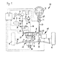
- Fig. 1 is a steering system 10 for a further not illustrated motor vehicle illustrated in the form of a passenger car.
- the steering system 10 is a steering handle 12 in the form of a steering wheel of a driver of the motor vehicle actuated. It is basically of the driver a hand angle and a manual torque transmitted to a steering gear 14, of which operated from a rack or a steering linkage 16 and thus steerable wheels 18 of the motor vehicle are moved.
- the steering system 10 is provided with a hydraulic power steering device 20, in which at the steering linkage 16 a synchronizing cylinder 22 with a first and a second chamber 24 or 26 is provided for hydraulic fluid. Between Chambers 24 and 26, a displaceably mounted piston 28 is arranged, which with the steering linkage 16 is coupled force-transmitting. In a connection line between the chambers 24 and 26 a pressure measuring device 30 is arranged, to determine the differential pressure between the chambers 24 and 26.
- first hydraulic line 32 From the first chamber 24 is a first hydraulic line 32 and from the second chamber 26, a second hydraulic line 34 to a Electromagnetically remotely controllable 4/4-way valve 36 out.
- 4/4-way valve 36 At the 4/4-way valve 36 are also a third hydraulic line 38 and a fourth hydraulic line 40 connected.
- This hydraulic line 40 is at a Reservoir 42 out while on the line 38 by means of a power steering pump 44 in the form of a constant pump or a variable displacement pump as needed hydraulic pressure can be generated.
- the power steering pump 44 is to a remotely controllable to be operated clutch 46 of a drive unit 48 in the form of an internal combustion engine of the Motor vehicle driven.
- the power steering pump 44 then sucks from the top mentioned reservoir 42 Hydaulikfluid and promotes this by a Check valve 50 to an electromagnetically remotely controllable shut-off valve 52nd Before the shut-off valve 52 branches a hydraulic line to a pressure accumulator 54 from, on which further a pressure sensor 56 is arranged.
- a Pressure accumulator 54 Before the shut-off valve 52 branches a hydraulic line to a pressure accumulator 54 from, on which further a pressure sensor 56 is arranged.
- When closed Shut-off valve 52 is therefore mainly the pressure accumulator 54 with hydraulic fluid supplied while open shut-off valve 52 in the third line 38 pressure provided.
- a Relief valve 58 is arranged, which by an associated hydraulic Line leads to the fourth line 40 and thus to the reservoir 42.
- a Overlay steering device 60 is provided, in particular by means of a Overlay gear 62 is formed.
- the superposition gear 62 is in a steering column 64 between the steering handle 12 and the steering gear 14th interposed and is driven by an electric motor 66.
- an angle measuring device 68 and a torque measuring device 70 and a electronic control unit 72 is provided.
- the controller 72 is dashed over lines shown in particular with the measuring devices 68 and 70, the Pressure measuring device 30, the pressure sensor 56 and the 4/4-way valve 36 and the shut-off valve 52 operatively connected.
- Steering system 10 is to do with the superposition steering system 60 on the Basis of the determined at the measuring devices 68 and 70 angle and Torque values as well as on the basis of further dynamic driving parameters of the controlling motor vehicle with the control unit 72 a required steering angle predetermined.
- the steering angle is then by appropriate influence on the Overlay steering device 60 and their superposition gear 62 set.
- the driver of the vehicle from the set wheel steering angle independent hand moment in the form of a support or counter torque to pretend is by the controller 72 and the power steering device 20 and their synchronizing cylinder 22 generates a force on the steering gear 14, which is then transmitted via the steering column 64 as a manual torque to the driver.
Landscapes
- Engineering & Computer Science (AREA)
- Chemical & Material Sciences (AREA)
- Combustion & Propulsion (AREA)
- Transportation (AREA)
- Mechanical Engineering (AREA)
- Steering Control In Accordance With Driving Conditions (AREA)
- Power Steering Mechanism (AREA)
Applications Claiming Priority (6)
| Application Number | Priority Date | Filing Date | Title |
|---|---|---|---|
| DE10337635 | 2003-08-16 | ||
| DE10337635 | 2003-08-16 | ||
| DE2003137954 DE10337954A1 (de) | 2003-08-19 | 2003-08-19 | Hilfskraftunterstütztes Lenksystem für ein Kraftfahrzeug, mit hydraulischer offener Mitte |
| DE10337954 | 2003-08-19 | ||
| DE10351768A DE10351768A1 (de) | 2003-08-16 | 2003-11-06 | Lenksystem für ein Kraftfahrzeug mit einer Servolenkeinrichtung |
| DE10351768 | 2003-11-06 |
Publications (3)
| Publication Number | Publication Date |
|---|---|
| EP1508498A2 true EP1508498A2 (fr) | 2005-02-23 |
| EP1508498A3 EP1508498A3 (fr) | 2005-05-11 |
| EP1508498B1 EP1508498B1 (fr) | 2007-04-04 |
Family
ID=34068678
Family Applications (1)
| Application Number | Title | Priority Date | Filing Date |
|---|---|---|---|
| EP04103626A Expired - Lifetime EP1508498B1 (fr) | 2003-08-16 | 2004-07-28 | Système de direction pour un véhicule avec un dispositif de direction assistée |
Country Status (2)
| Country | Link |
|---|---|
| EP (1) | EP1508498B1 (fr) |
| DE (1) | DE502004003374D1 (fr) |
Cited By (5)
| Publication number | Priority date | Publication date | Assignee | Title |
|---|---|---|---|---|
| EP1584539A3 (fr) * | 2004-04-07 | 2005-11-16 | AGCO GmbH | Système de direction hydro-statique |
| FR2891794A1 (fr) * | 2005-10-12 | 2007-04-13 | Peugeot Citroen Automobiles Sa | Dispositif d'ajout d'angle de braquage des roues directrices d'un vehicule automobile |
| WO2007134888A1 (fr) * | 2006-05-18 | 2007-11-29 | Zf Lenksysteme Gmbh | Système de direction pour véhicule |
| CN102700605A (zh) * | 2012-05-30 | 2012-10-03 | 潍柴动力股份有限公司 | 一种混合动力车液压助力转向系统及控制方法 |
| WO2014199021A1 (fr) * | 2013-06-12 | 2014-12-18 | Université De Valenciennes Et Du Hainaut-Cambrésis | Système de direction pour véhicule |
Families Citing this family (1)
| Publication number | Priority date | Publication date | Assignee | Title |
|---|---|---|---|---|
| DE202011005545U1 (de) * | 2011-03-09 | 2013-06-21 | TAKATA Aktiengesellschaft | Lenkrad für ein Kraftfahrzeug |
Family Cites Families (5)
| Publication number | Priority date | Publication date | Assignee | Title |
|---|---|---|---|---|
| DE4409928A1 (de) * | 1994-03-23 | 1995-09-28 | Bosch Gmbh Robert | Hydraulischer Stellantrieb für die Achslenkung eines Kraftfahrzeuges |
| DE10152704A1 (de) * | 2001-10-19 | 2003-07-17 | Mercedes Benz Lenkungen Gmbh | Elektrische Kraftfahrzeugservolenkung mit Überlagerungsgetriebe |
| DE10160716A1 (de) * | 2001-12-11 | 2003-06-18 | Mercedes Benz Lenkungen Gmbh | Lenkung mit angetriebenem Umlaufgetriebe zur Erzeugung eines bestimmten Handmoments am Lenkrad |
| DE10210368A1 (de) * | 2002-03-08 | 2003-09-25 | Daimler Chrysler Ag | Lenkwellenstrang |
| DE10245975A1 (de) * | 2002-10-02 | 2004-04-22 | Zf Lenksysteme Gmbh | Hilfskraftlenkung mit hydraulischer Hilfskraftunterstützung |
-
2004
- 2004-07-28 DE DE200450003374 patent/DE502004003374D1/de not_active Expired - Lifetime
- 2004-07-28 EP EP04103626A patent/EP1508498B1/fr not_active Expired - Lifetime
Cited By (5)
| Publication number | Priority date | Publication date | Assignee | Title |
|---|---|---|---|---|
| EP1584539A3 (fr) * | 2004-04-07 | 2005-11-16 | AGCO GmbH | Système de direction hydro-statique |
| FR2891794A1 (fr) * | 2005-10-12 | 2007-04-13 | Peugeot Citroen Automobiles Sa | Dispositif d'ajout d'angle de braquage des roues directrices d'un vehicule automobile |
| WO2007134888A1 (fr) * | 2006-05-18 | 2007-11-29 | Zf Lenksysteme Gmbh | Système de direction pour véhicule |
| CN102700605A (zh) * | 2012-05-30 | 2012-10-03 | 潍柴动力股份有限公司 | 一种混合动力车液压助力转向系统及控制方法 |
| WO2014199021A1 (fr) * | 2013-06-12 | 2014-12-18 | Université De Valenciennes Et Du Hainaut-Cambrésis | Système de direction pour véhicule |
Also Published As
| Publication number | Publication date |
|---|---|
| EP1508498B1 (fr) | 2007-04-04 |
| EP1508498A3 (fr) | 2005-05-11 |
| DE502004003374D1 (de) | 2007-05-16 |
Similar Documents
| Publication | Publication Date | Title |
|---|---|---|
| DE102007004369B4 (de) | Fahrzeuglenksystem | |
| EP1508494B1 (fr) | Système de direction assistée pour véhicule, avec centre ouvert hydraulique | |
| DE2851773A1 (de) | Hydraulische lenkeinrichtung mit rueckwirkung auf die betaetigungseinrichtung | |
| EP1251059B1 (fr) | Procédé de commande d'un système de direction assistée | |
| DE10060832A1 (de) | Fremdkraft-Lenkeinrichtung | |
| EP1508498B1 (fr) | Système de direction pour un véhicule avec un dispositif de direction assistée | |
| EP2421741B1 (fr) | Système de direction de véhicule du type à commande électrique | |
| DE19935073A1 (de) | Steer-by-wire-Lenkung mit hydraulischem Druckspeicher | |
| DE10351768A1 (de) | Lenksystem für ein Kraftfahrzeug mit einer Servolenkeinrichtung | |
| EP1447307B1 (fr) | Procédé pour déterminer le débit de fluide de la direction et dispositif de direction hydraulique avec amplification de débit | |
| DE102004051194A1 (de) | Lenksystem für Fahrzeuge | |
| DE102004038936C5 (de) | Hydraulische Servolenkung und Verfahren zum Betrieb einer hydraulischen Servolenkung | |
| WO2002012052A1 (fr) | Direction de vehicule | |
| DE10250300A1 (de) | Servo-Lenkanlage | |
| EP2018309B1 (fr) | Systeme de direction pour vehicule | |
| EP1508499B1 (fr) | Système de direction pour un véhicule avec un dispositif de direction assistée | |
| DE19929428A1 (de) | Elektrohydraulisches Lenksystem für Kraftfahrzeuge | |
| DE10320846A1 (de) | Lenkungsvorrichtung für Kraftfahrzeuge | |
| EP1737722B1 (fr) | Systeme de direction assistee hydraulique a centre ouvert et son procede de fonctionnement | |
| DE102006014194B4 (de) | Hydrauliksystem zur Versorgung eines Aktuators in einem Kraftfahrzeug | |
| EP1812275B1 (fr) | Direction assistee hydraulique | |
| DE10048697A1 (de) | Steer-by-Wire-Lenkanlage mit Zahnstangen-Hydrolenksteller | |
| EP1848624A1 (fr) | Systeme de direction electrohydraulique de vehicule presentant une caracteristique de pression lineaire | |
| DE10060374A1 (de) | Steer-by-Wire-Lenkung mit hydraulischem Feedback-Aktuator | |
| WO2007090577A1 (fr) | Dispositif de direction assistée hydraulique |
Legal Events
| Date | Code | Title | Description |
|---|---|---|---|
| PUAI | Public reference made under article 153(3) epc to a published international application that has entered the european phase |
Free format text: ORIGINAL CODE: 0009012 |
|
| AK | Designated contracting states |
Kind code of ref document: A2 Designated state(s): AT BE BG CH CY CZ DE DK EE ES FI FR GB GR HU IE IT LI LU MC NL PL PT RO SE SI SK TR |
|
| AX | Request for extension of the european patent |
Extension state: AL HR LT LV MK |
|
| PUAL | Search report despatched |
Free format text: ORIGINAL CODE: 0009013 |
|
| AK | Designated contracting states |
Kind code of ref document: A3 Designated state(s): AT BE BG CH CY CZ DE DK EE ES FI FR GB GR HU IE IT LI LU MC NL PL PT RO SE SI SK TR |
|
| AX | Request for extension of the european patent |
Extension state: AL HR LT LV MK |
|
| RIC1 | Information provided on ipc code assigned before grant |
Ipc: 7B 62D 5/04 B Ipc: 7B 62D 5/09 B Ipc: 7B 62D 5/00 A Ipc: 7B 62D 5/065 B Ipc: 7B 62D 5/06 B |
|
| 17P | Request for examination filed |
Effective date: 20050907 |
|
| AKX | Designation fees paid |
Designated state(s): DE FR GB IT |
|
| GRAP | Despatch of communication of intention to grant a patent |
Free format text: ORIGINAL CODE: EPIDOSNIGR1 |
|
| GRAS | Grant fee paid |
Free format text: ORIGINAL CODE: EPIDOSNIGR3 |
|
| GRAA | (expected) grant |
Free format text: ORIGINAL CODE: 0009210 |
|
| AK | Designated contracting states |
Kind code of ref document: B1 Designated state(s): DE FR GB IT |
|
| REG | Reference to a national code |
Ref country code: GB Ref legal event code: FG4D Free format text: NOT ENGLISH |
|
| GBT | Gb: translation of ep patent filed (gb section 77(6)(a)/1977) |
Effective date: 20070410 |
|
| REF | Corresponds to: |
Ref document number: 502004003374 Country of ref document: DE Date of ref document: 20070516 Kind code of ref document: P |
|
| ET | Fr: translation filed | ||
| PLBE | No opposition filed within time limit |
Free format text: ORIGINAL CODE: 0009261 |
|
| STAA | Information on the status of an ep patent application or granted ep patent |
Free format text: STATUS: NO OPPOSITION FILED WITHIN TIME LIMIT |
|
| 26N | No opposition filed |
Effective date: 20080107 |
|
| REG | Reference to a national code |
Ref country code: FR Ref legal event code: PLFP Year of fee payment: 13 |
|
| PGFP | Annual fee paid to national office [announced via postgrant information from national office to epo] |
Ref country code: IT Payment date: 20160727 Year of fee payment: 13 |
|
| PGFP | Annual fee paid to national office [announced via postgrant information from national office to epo] |
Ref country code: FR Payment date: 20160722 Year of fee payment: 13 |
|
| REG | Reference to a national code |
Ref country code: FR Ref legal event code: ST Effective date: 20180330 |
|
| PG25 | Lapsed in a contracting state [announced via postgrant information from national office to epo] |
Ref country code: FR Free format text: LAPSE BECAUSE OF NON-PAYMENT OF DUE FEES Effective date: 20170731 |
|
| PG25 | Lapsed in a contracting state [announced via postgrant information from national office to epo] |
Ref country code: IT Free format text: LAPSE BECAUSE OF NON-PAYMENT OF DUE FEES Effective date: 20170728 |
|
| PGFP | Annual fee paid to national office [announced via postgrant information from national office to epo] |
Ref country code: GB Payment date: 20220725 Year of fee payment: 19 Ref country code: DE Payment date: 20220621 Year of fee payment: 19 |
|
| P01 | Opt-out of the competence of the unified patent court (upc) registered |
Effective date: 20230427 |
|
| REG | Reference to a national code |
Ref country code: DE Ref legal event code: R119 Ref document number: 502004003374 Country of ref document: DE |
|
| GBPC | Gb: european patent ceased through non-payment of renewal fee |
Effective date: 20230728 |
|
| PG25 | Lapsed in a contracting state [announced via postgrant information from national office to epo] |
Ref country code: DE Free format text: LAPSE BECAUSE OF NON-PAYMENT OF DUE FEES Effective date: 20240201 Ref country code: GB Free format text: LAPSE BECAUSE OF NON-PAYMENT OF DUE FEES Effective date: 20230728 |