EP1508505A2 - Fahrzeug-Fahrregler - Google Patents
Fahrzeug-Fahrregler Download PDFInfo
- Publication number
- EP1508505A2 EP1508505A2 EP04255036A EP04255036A EP1508505A2 EP 1508505 A2 EP1508505 A2 EP 1508505A2 EP 04255036 A EP04255036 A EP 04255036A EP 04255036 A EP04255036 A EP 04255036A EP 1508505 A2 EP1508505 A2 EP 1508505A2
- Authority
- EP
- European Patent Office
- Prior art keywords
- vehicle
- control device
- driving control
- automatic
- driving
- Prior art date
- Legal status (The legal status is an assumption and is not a legal conclusion. Google has not performed a legal analysis and makes no representation as to the accuracy of the status listed.)
- Granted
Links
- 230000008859 change Effects 0.000 claims description 4
- 230000002159 abnormal effect Effects 0.000 abstract description 13
- 238000010586 diagram Methods 0.000 description 7
- 230000014509 gene expression Effects 0.000 description 5
- 238000004891 communication Methods 0.000 description 4
- 238000000034 method Methods 0.000 description 4
- 238000001514 detection method Methods 0.000 description 3
- 239000000284 extract Substances 0.000 description 2
- 239000004973 liquid crystal related substance Substances 0.000 description 2
- 230000007246 mechanism Effects 0.000 description 2
Images




Classifications
-
- B—PERFORMING OPERATIONS; TRANSPORTING
- B60—VEHICLES IN GENERAL
- B60T—VEHICLE BRAKE CONTROL SYSTEMS OR PARTS THEREOF; BRAKE CONTROL SYSTEMS OR PARTS THEREOF, IN GENERAL; ARRANGEMENT OF BRAKING ELEMENTS ON VEHICLES IN GENERAL; PORTABLE DEVICES FOR PREVENTING UNWANTED MOVEMENT OF VEHICLES; VEHICLE MODIFICATIONS TO FACILITATE COOLING OF BRAKES
- B60T8/00—Arrangements for adjusting wheel-braking force to meet varying vehicular or ground-surface conditions, e.g. limiting or varying distribution of braking force
- B60T8/17—Using electrical or electronic regulation means to control braking
- B60T8/1755—Brake regulation specially adapted to control the stability of the vehicle, e.g. taking into account yaw rate or transverse acceleration in a curve
- B60T8/17557—Brake regulation specially adapted to control the stability of the vehicle, e.g. taking into account yaw rate or transverse acceleration in a curve specially adapted for lane departure prevention
-
- B—PERFORMING OPERATIONS; TRANSPORTING
- B62—LAND VEHICLES FOR TRAVELLING OTHERWISE THAN ON RAILS
- B62D—MOTOR VEHICLES; TRAILERS
- B62D1/00—Steering controls, i.e. means for initiating a change of direction of the vehicle
- B62D1/24—Steering controls, i.e. means for initiating a change of direction of the vehicle not vehicle-mounted
- B62D1/28—Steering controls, i.e. means for initiating a change of direction of the vehicle not vehicle-mounted non-mechanical, e.g. following a line or other known markers
- B62D1/286—Systems for interrupting non-mechanical steering due to driver intervention
-
- B—PERFORMING OPERATIONS; TRANSPORTING
- B60—VEHICLES IN GENERAL
- B60T—VEHICLE BRAKE CONTROL SYSTEMS OR PARTS THEREOF; BRAKE CONTROL SYSTEMS OR PARTS THEREOF, IN GENERAL; ARRANGEMENT OF BRAKING ELEMENTS ON VEHICLES IN GENERAL; PORTABLE DEVICES FOR PREVENTING UNWANTED MOVEMENT OF VEHICLES; VEHICLE MODIFICATIONS TO FACILITATE COOLING OF BRAKES
- B60T2201/00—Particular use of vehicle brake systems; Special systems using also the brakes; Special software modules within the brake system controller
- B60T2201/08—Lane monitoring; Lane Keeping Systems
-
- B—PERFORMING OPERATIONS; TRANSPORTING
- B60—VEHICLES IN GENERAL
- B60T—VEHICLE BRAKE CONTROL SYSTEMS OR PARTS THEREOF; BRAKE CONTROL SYSTEMS OR PARTS THEREOF, IN GENERAL; ARRANGEMENT OF BRAKING ELEMENTS ON VEHICLES IN GENERAL; PORTABLE DEVICES FOR PREVENTING UNWANTED MOVEMENT OF VEHICLES; VEHICLE MODIFICATIONS TO FACILITATE COOLING OF BRAKES
- B60T2201/00—Particular use of vehicle brake systems; Special systems using also the brakes; Special software modules within the brake system controller
- B60T2201/08—Lane monitoring; Lane Keeping Systems
- B60T2201/083—Lane monitoring; Lane Keeping Systems using active brake actuation
-
- B—PERFORMING OPERATIONS; TRANSPORTING
- B60—VEHICLES IN GENERAL
- B60T—VEHICLE BRAKE CONTROL SYSTEMS OR PARTS THEREOF; BRAKE CONTROL SYSTEMS OR PARTS THEREOF, IN GENERAL; ARRANGEMENT OF BRAKING ELEMENTS ON VEHICLES IN GENERAL; PORTABLE DEVICES FOR PREVENTING UNWANTED MOVEMENT OF VEHICLES; VEHICLE MODIFICATIONS TO FACILITATE COOLING OF BRAKES
- B60T2201/00—Particular use of vehicle brake systems; Special systems using also the brakes; Special software modules within the brake system controller
- B60T2201/08—Lane monitoring; Lane Keeping Systems
- B60T2201/087—Lane monitoring; Lane Keeping Systems using active steering actuation
-
- B—PERFORMING OPERATIONS; TRANSPORTING
- B60—VEHICLES IN GENERAL
- B60T—VEHICLE BRAKE CONTROL SYSTEMS OR PARTS THEREOF; BRAKE CONTROL SYSTEMS OR PARTS THEREOF, IN GENERAL; ARRANGEMENT OF BRAKING ELEMENTS ON VEHICLES IN GENERAL; PORTABLE DEVICES FOR PREVENTING UNWANTED MOVEMENT OF VEHICLES; VEHICLE MODIFICATIONS TO FACILITATE COOLING OF BRAKES
- B60T2210/00—Detection or estimation of road or environment conditions; Detection or estimation of road shapes
- B60T2210/30—Environment conditions or position therewithin
- B60T2210/36—Global Positioning System [GPS]
-
- B—PERFORMING OPERATIONS; TRANSPORTING
- B60—VEHICLES IN GENERAL
- B60W—CONJOINT CONTROL OF VEHICLE SUB-UNITS OF DIFFERENT TYPE OR DIFFERENT FUNCTION; CONTROL SYSTEMS SPECIALLY ADAPTED FOR HYBRID VEHICLES; ROAD VEHICLE DRIVE CONTROL SYSTEMS FOR PURPOSES NOT RELATED TO THE CONTROL OF A PARTICULAR SUB-UNIT
- B60W30/00—Purposes of road vehicle drive control systems not related to the control of a particular sub-unit, e.g. of systems using conjoint control of vehicle sub-units
- B60W30/08—Active safety systems predicting or avoiding probable or impending collision or attempting to minimise its consequences
- B60W30/09—Taking automatic action to avoid collision, e.g. braking and steering
Definitions
- the present invention relates to a driving control device for controlling automatic driving of a vehicle by controlling the vehicle speed and automatic steering corresponding to a planned route based upon the set planning route, the current position of the vehicle on the planning route, and the current route of the vehicle.
- GPS Global Positioning System
- Japanese Unexamined Patent Application Publication No. 10-76964 wherein information with regard to the road ahead of the vehicle (painted line on the road) is detected with a CCD camera, and the steering angle is determined based upon determination results of the moving direction of the vehicle in order to automatically control a steering device.
- the system determines whether any abnormal situation occurs and whether the automatic driving mode can be cancelled or not. In this case, the automatic driving is maintained until the system makes a determination that the automatic driving mode can be cancelled from the time of the system making a determination that the automatic driving mode cannot be cancelled.
- the present invention has been made in order to solve the aforementioned problems, and accordingly, it is an object thereof to provide a driving control device for detecting abnormal situations during automatic driving with high precision based upon the control error and the intent of the user so as to control driving of the vehicle according to the intent of the user.
- a driving control device for a vehicle comprises: planning-route setting means for setting a planning route along which the vehicle is to be driven; vehicle-position computing means for computing the position of the vehicle; vehicle-direction estimating means for estimating the direction of the vehicle; and driving control means for controlling automatic driving of the vehicle based upon the vehicle position, the vehicle direction, and the planning route, and the driving control means stop driving control of the vehicle in the event that the differential value of the distance between the future position of the vehicle ahead of the current position thereof and the planning route exceeds a predetermined threshold, and the steering torque exceeds a predetermined threshold.
- a GPS known as an RTK (Real-Time Kinematic) GPS is employed. That is to say, the information (data such as satellite-orbit information for performing positioning calculation and so forth) from artificial satellites (GPS satellites) 1 orbiting the Earth is received by a base station 2 and a vehicle 3 serving as a moving station.
- RTK Real-Time Kinematic
- the base station 2 is installed at a position which has been measured beforehand with sufficient precision, and principally includes a GPS antenna 2a, a GPS receiver 2b, and a wireless communication device 2c.
- the base station 2 transmits the phase information with regard to the radio wave from the GPS satellites 1, the pseudo range, and the position coordinates of the base station 2, to a point which is to be measured, i.e., the vehicle 3 as the moving station, using the wireless communication device 2c.
- the data transmitted from the base station 2 to the vehicle 3 includes: error correction data; pseudo-range correction data; and the position coordinates of the base station 2.
- the vehicle 3 includes a GPS antenna 3a, a GPS receiver 3b, and a wireless communication device 3c.
- the GPS receiver 3b calculates the position (position coordinates) of the vehicle with high precision (e.g., margin of error of 1 to 5 cm) in real time by analyzing the error correction data, the pseudo-range correction data, and the position coordinates of the base station 2, received from the base station 2 (data received through the wireless communication device 3c) and the information directly received from the GPS satellites 1.
- the GPS receiver 3b has a function as vehicle-position detecting means for detecting the position of the vehicle.
- the vehicle 3 includes a control device 3d having functions of vehicle-direction estimating means, planning-route setting means, and driving control means.
- the control device 3d is connected to the GPS receiver 3b through an unshown serial-CAN converter or the like for receiving the information with regard to the current position of the vehicle.
- the control device 3d is connected to sensors such as a speed sensor 3e for detecting the speed V of the vehicle, a steering-angle sensor 3f for detecting the steering angle ⁇ H, a steering torque sensor 3g for detecting steering torque TH applied from the user, and so forth, and a main switch 3h for switching to the automatic-driving control mode.
- control device 3d of the vehicle 3 includes an unshown storage medium such as a hard disk, CD, DVD, or the like, which has map information stored therein necessary for the automatic-driving control.
- the map information is suitably displayed on a liquid crystal display 3i mounted on a dash board thereof, for example.
- the current vehicle position and the optimum route from the current position to the destination are calculated and displayed on a map shown on the liquid crystal display 3i.
- the calculated optimum route is set as a planning route (formed of a node line) along which the vehicle is to be driven.
- control device 3d of the vehicle 3 is connected to actuators for performing automatic-driving control, such as an electric throttle control device 3j, a brake control device 3k, and an electric power steering control device 31.
- control of the vehicle speed is executed in the automatic-driving control mode, whereby the target vehicle speed is determined.
- the control device 3d outputs signals to the electric throttle control device 3j so as to drive a throttle 3m such that the vehicle is accelerated or decelerated in order to maintain the target vehicle speed. Furthermore, in the event that deceleration of the vehicle must be made beyond a predetermined deceleration, the control device 3d outputs signals to the brake control device 3k so as to operate an automatic brake.
- control device 3d detects any abnormal situation of automatic driving (a situation wherein the user requests canceling of automatic driving) during diagnostic processing according to an automatic-driving diagnostic program
- the control device 3d outputs signals to the brake control device 3k so as to drive the automatic brake such that deceleration of the vehicle is made with a predetermined deceleration.
- Step 101 the control device 3d reads the required parameters.
- the flow proceeds to S102, where the control device 3d extracts the previous position of the vehicle, approximately the length of the vehicle (e.g., 5 m) behind the current position, from vehicle-position-history information, and estimates the direction of the vehicle to be the direction passing through the current position of the vehicle and the previous position, 5 m behind the current position.
- the control device 3d extracts the previous position of the vehicle, approximately the length of the vehicle (e.g., 5 m) behind the current position, from vehicle-position-history information, and estimates the direction of the vehicle to be the direction passing through the current position of the vehicle and the previous position, 5 m behind the current position.
- control device 3d extracts the node on the planning route nearest to the current position of the vehicle.
- a predetermined viewing time e.g. 1.5 sec.
- the flow proceeds to S105, where the control device 3d determines a node on the planning route, approximately the viewing distance calculated in S104 ahead of the current position of the vehicle, and sets the node thus determined as a node toward which the vehicle is to be driven.
- control device 3d computes the lateral deviation of the direction of the vehicle from the node toward which the vehicle is to be driven, as the node deviation ⁇ D.
- Gp represents a proportional gain
- Gd represents a differential gain
- Kp is a proportional gain
- Kd is a differential gain
- Ki is an integral gain
- the control device 3d reads required parameters in S201, and computes the radius of curvature R of the planning route in S202. For example, the control device 3d computes the radius of curvature R by calculating the radius of the circle passing through the three nodes on the planning route. Note that the control device 3d may select: the node toward which the vehicle is to be driven, and the nodes adjacent to the aforementioned node, as shown in Fig.
- control device 3d selects the node toward which the vehicle is to be driven, and the nodes adjacent to the nearest node.
- the control device 3d selects three nodes of P1(x1, y1), P2(x2, y2), and P3(x3, y3), in the coordinate space of X and Y.
- the X axis represents the lateral direction of the vehicle 3
- the Y axis represents the longitudinal direction thereof.
- Sa represents the area of the triangle P1-P2-P3, and is calculated by Expression (4) described below.
- Sa ( ⁇ • ( ⁇ - A) • ( ⁇ - B) • ( ⁇ - C)) 1/2
- ⁇ represents (A + B + C)/2.
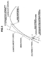
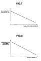
- the control device 3d determines a change history of the target node deviation ⁇ D. Namely, a deviation threshold ⁇ Dc for being compared with the differential value (d ⁇ D/dt) of the target node deviation ⁇ D is determined. Note that the target node deviation ⁇ D changes from ⁇ D1 to ⁇ D3 through ⁇ D2 along the planning route as shown in Fig. 6. The greater the radius of curvature R is, the smaller the deviation threshold ⁇ Dc is set to be, as shown in the relation in Fig. 7.
- the flow proceeds to S204, where the control device 3d determines a steering torque threshold Tc for being compared with the absolute value
- the flow proceeds to S205, where the control device 3d makes a comparison between the differential value (d ⁇ D/dt) of the target node deviation ⁇ D and the deviation threshold ⁇ Dc.
- the control device 3d has determined that the differential value (d ⁇ D/dt) of the target node deviation ⁇ D is less than the deviation threshold ⁇ Dc (i.e., (d ⁇ D/dt) ⁇ ⁇ Dc)
- the following processing according to the program is skipped.
- the control device 3d makes a comparison between the absolute value
- the flow proceeds to S208, where the control device 3d outputs signals to the electric power steering control device 31 so as to cancel automatic steering, whereby the system enters a normal power steering mode. Subsequently, the flow proceeds to S209, where the control device 3d cancels the automatic-driving control mode, and turns off the main switch 3h.
- the flow proceeds to S210, where the control device 3d determines whether or not the main switch 3h is turned on again. In the event that determination has been made that the main switch 3h is off, the flow returns to S209, whereby the system maintains the normal power steering mode. Upon the user turning on the main switch 3h, the flow skips this loop so that the system enters the automatic-driving control mode.
- the system may determine unintentional steering actions of the user to be an abnormal situation of driving control.
- the system determines that the user requests cancellation of the automatic driving (e.g., a case wherein the user avoids an obstacle ahead of the vehicle), and the system detects this situation as an abnormal situation, thereby enabling driving control matching the intent of the user.
- the automatic driving e.g., a case wherein the user avoids an obstacle ahead of the vehicle
- the present invention is not restricted to the aforementioned arrangement.
- the system includes a CCD camera for taking images of the road ahead of the vehicle, and painted lines on the left and the right sides of the road in the images are detected with known image recognition, and a planning route along which the vehicle is to be driven is set along a line on the middle portion between the left and right painted lines, or on a line a predetermined distance from either thereof.
- the system computes the position of the vehicle based upon the distance between one of the painted lines and the vehicle 3, and estimates the direction of the vehicle based upon change in the vehicle position over time. Furthermore, in the same way as with the above-described embodiment, the system calculates the differential value of the distance deviation of the future position of the vehicle, a predetermined distance ahead of the current position of the vehicle 3, from the planning route. Only in the event that the calculated differential value of the distance is equal to or greater than the deviation threshold ADc, and the absolute value ITHI of the steering torque TH is equal to or greater than the steering torque threshold Tc, the system cancels the automatic-driving control mode.
- An arrangement having such a configuration employing an image recognition technique using a CCD camera has the same advantages as with the above-described embodiment.
- the present invention enables precise detection of abnormal situations during automatic driving, giving consideration to the control error and the intent of the user, thereby enabling driving control matching the intent of the user.
Landscapes
- Engineering & Computer Science (AREA)
- Transportation (AREA)
- Mechanical Engineering (AREA)
- Chemical & Material Sciences (AREA)
- Combustion & Propulsion (AREA)
- Steering Control In Accordance With Driving Conditions (AREA)
- Power Steering Mechanism (AREA)
Applications Claiming Priority (2)
| Application Number | Priority Date | Filing Date | Title |
|---|---|---|---|
| JP2003297998A JP4435519B2 (ja) | 2003-08-21 | 2003-08-21 | 車両の走行制御装置 |
| JP2003297998 | 2003-08-21 |
Publications (3)
| Publication Number | Publication Date |
|---|---|
| EP1508505A2 true EP1508505A2 (de) | 2005-02-23 |
| EP1508505A3 EP1508505A3 (de) | 2009-09-30 |
| EP1508505B1 EP1508505B1 (de) | 2013-01-30 |
Family
ID=34056255
Family Applications (1)
| Application Number | Title | Priority Date | Filing Date |
|---|---|---|---|
| EP04255036A Expired - Lifetime EP1508505B1 (de) | 2003-08-21 | 2004-08-20 | Fahrzeug-Fahrregler |
Country Status (3)
| Country | Link |
|---|---|
| US (1) | US7177760B2 (de) |
| EP (1) | EP1508505B1 (de) |
| JP (1) | JP4435519B2 (de) |
Cited By (5)
| Publication number | Priority date | Publication date | Assignee | Title |
|---|---|---|---|---|
| EP1864889A2 (de) | 2006-06-07 | 2007-12-12 | Jtekt Corporation | Fahrzeuglenkungssystem |
| WO2014178445A1 (en) * | 2013-05-01 | 2014-11-06 | Toyota Jidosha Kabushiki Kaisha | Driving support apparatus and driving support method |
| DE102005049071B4 (de) * | 2005-10-13 | 2015-04-09 | Robert Bosch Gmbh | LKS-System mit I-Regler |
| WO2016116242A1 (de) * | 2015-01-22 | 2016-07-28 | Volkswagen Aktiengesellschaft | Lenksystem für ein automatisiertes fahren eines kraftfahrzeuges |
| EP3020616A4 (de) * | 2013-07-08 | 2016-08-03 | Nissan Motor | Fahrzeuglenksteuerungsvorrichtung und fahrzeuglenksteuerungsverfahren |
Families Citing this family (33)
| Publication number | Priority date | Publication date | Assignee | Title |
|---|---|---|---|---|
| JP4807728B2 (ja) * | 2005-05-17 | 2011-11-02 | 富士重工業株式会社 | 車両の走行制御装置 |
| JP2007132747A (ja) * | 2005-11-09 | 2007-05-31 | Xanavi Informatics Corp | ナビゲーションシステム及び情報取得方法 |
| JP4587050B2 (ja) * | 2006-06-13 | 2010-11-24 | 株式会社ジェイテクト | 車両用操舵装置 |
| US8509982B2 (en) | 2010-10-05 | 2013-08-13 | Google Inc. | Zone driving |
| KR20120053713A (ko) * | 2010-11-18 | 2012-05-29 | 에스엘 주식회사 | 차량용 카메라의 제어 장치 및 방법 |
| DE102010054066A1 (de) * | 2010-12-10 | 2012-06-14 | GM Global Technology Operations LLC | Verfahren zum Betreiben eines Sensors eines Fahrzeugs und Fahrerassistenzsystem für ein Fahrzeug |
| US9333975B2 (en) | 2011-02-05 | 2016-05-10 | Ford Global Technologies, Llc | Method and system to detect and mitigate customer dissatisfaction with performance of automatic mode selection system |
| US8965633B2 (en) * | 2011-09-02 | 2015-02-24 | GM Global Technology Operations LLC | System and method for speed adaptive steering override detection during automated lane centering |
| KR101405679B1 (ko) * | 2011-10-11 | 2014-06-13 | 현대자동차주식회사 | 차량 위치 정보 기반 비정상 운전 판정 및 경보 시스템 |
| US8718861B1 (en) * | 2012-04-11 | 2014-05-06 | Google Inc. | Determining when to drive autonomously |
| CN104334430A (zh) * | 2012-05-23 | 2015-02-04 | 丰田自动车株式会社 | 驾驶支援控制装置 |
| US8793046B2 (en) | 2012-06-01 | 2014-07-29 | Google Inc. | Inferring state of traffic signal and other aspects of a vehicle's environment based on surrogate data |
| US9633564B2 (en) | 2012-09-27 | 2017-04-25 | Google Inc. | Determining changes in a driving environment based on vehicle behavior |
| US8949016B1 (en) | 2012-09-28 | 2015-02-03 | Google Inc. | Systems and methods for determining whether a driving environment has changed |
| JP6278565B2 (ja) | 2014-08-11 | 2018-02-14 | 本田技研工業株式会社 | 自動運転車両制御装置 |
| US9321461B1 (en) | 2014-08-29 | 2016-04-26 | Google Inc. | Change detection using curve alignment |
| US9248834B1 (en) | 2014-10-02 | 2016-02-02 | Google Inc. | Predicting trajectories of objects based on contextual information |
| DE112016002177T5 (de) | 2015-05-14 | 2018-01-25 | Honda Motor Co., Ltd. | Automatische Fahrtsteuerungsvorrichtung |
| MX390330B (es) * | 2015-07-21 | 2025-03-20 | Nissan Motor | Dispositivo de plan de conduccion, dispositivo de apoyo de viaje, y metodo de plan de conduccion. |
| JP7314874B2 (ja) * | 2015-11-04 | 2023-07-26 | トヨタ自動車株式会社 | 自動運転システム、自動運転装置、自動運転方法 |
| FR3050161B1 (fr) * | 2016-04-13 | 2018-04-06 | Renault S.A.S | Dispositif de suivi de trajectoire d’un vehicule |
| DE102016219757A1 (de) * | 2016-10-11 | 2018-04-12 | Volkswagen Aktiengesellschaft | Ausweichunterstützung für ein Fahrzeug |
| CN107264534B (zh) * | 2017-05-23 | 2019-07-09 | 北京理工大学 | 基于驾驶员经验模型的智能驾驶控制系统和方法、车辆 |
| JP6683178B2 (ja) | 2017-06-02 | 2020-04-15 | トヨタ自動車株式会社 | 自動運転システム |
| JP6568559B2 (ja) * | 2017-09-13 | 2019-08-28 | 株式会社Subaru | 車両の走行制御装置 |
| JP6655116B2 (ja) | 2018-03-29 | 2020-02-26 | 株式会社Subaru | 車両の運転支援システム |
| JP6691568B2 (ja) | 2018-03-29 | 2020-04-28 | 株式会社Subaru | 運転支援システム |
| US12016255B2 (en) * | 2019-07-05 | 2024-06-25 | Deere & Company | Methods and apparatus to control vehicle steering |
| DE102019217922B4 (de) * | 2019-11-20 | 2023-08-03 | Robert Bosch Gmbh | Verfahren zum Betrieb eines Fahrzeugs |
| EP4321405A4 (de) | 2021-04-09 | 2024-06-12 | Nissan Motor Co., Ltd. | Antriebssteuerungsverfahren für ein fahrzeug und antriebssteuerungsvorrichtung |
| CN113469648A (zh) * | 2021-06-25 | 2021-10-01 | 广州得尔塔影像技术有限公司 | 测试流程控制方法、系统、可读存储介质及控制终端 |
| CN115042780B (zh) * | 2022-05-25 | 2025-09-09 | 江铃汽车股份有限公司 | 一种横向辅助驾驶系统接管方法及系统 |
| JP7661987B2 (ja) | 2023-02-01 | 2025-04-15 | トヨタ自動車株式会社 | 車両制御システム |
Citations (1)
| Publication number | Priority date | Publication date | Assignee | Title |
|---|---|---|---|---|
| EP1063149A2 (de) | 1999-06-25 | 2000-12-27 | Honda Giken Kogyo Kabushiki Kaisha | Kraftfahrzeug- Lenkungssteuersystem |
Family Cites Families (16)
| Publication number | Priority date | Publication date | Assignee | Title |
|---|---|---|---|---|
| US5610815A (en) * | 1989-12-11 | 1997-03-11 | Caterpillar Inc. | Integrated vehicle positioning and navigation system, apparatus and method |
| JPH04273301A (ja) * | 1991-02-28 | 1992-09-29 | Toyota Motor Corp | 車両用自動運転装置 |
| GB9317983D0 (en) | 1993-08-28 | 1993-10-13 | Lucas Ind Plc | A driver assistance system for a vehicle |
| US5854987A (en) * | 1995-02-22 | 1998-12-29 | Honda Giken Kogyo Kabushiki Kaisha | Vehicle steering control system using navigation system |
| JP3605885B2 (ja) * | 1995-06-13 | 2004-12-22 | 日産自動車株式会社 | 車両の自動操舵装置 |
| JP3647538B2 (ja) * | 1996-02-12 | 2005-05-11 | 本田技研工業株式会社 | 車両操舵装置 |
| JP3622329B2 (ja) * | 1996-03-08 | 2005-02-23 | スズキ株式会社 | 車両操舵装置 |
| JP3728823B2 (ja) * | 1996-09-03 | 2005-12-21 | 日産自動車株式会社 | 車両用走行制御装置 |
| JP3166635B2 (ja) * | 1996-11-14 | 2001-05-14 | トヨタ自動車株式会社 | 車両の操舵制御装置 |
| US6282478B1 (en) * | 1997-07-10 | 2001-08-28 | Aisin Seiki Kabushiki Kaisha | Travelling direction correction apparatus |
| US6134491A (en) * | 1997-09-13 | 2000-10-17 | Honda Giken Kogyo Kabushiki Kaisha | Steering control system for vehicle |
| DE59809476D1 (de) * | 1997-11-03 | 2003-10-09 | Volkswagen Ag | Autonomes Fahrzeug und Verfahren zur Steuerung eines autonomen Fahrzeuges |
| US5926082A (en) | 1997-12-17 | 1999-07-20 | Caterpillar Inc. | Solenoid stator assembly |
| JP3731997B2 (ja) * | 1997-12-26 | 2006-01-05 | 光洋精工株式会社 | 車両のステアリング装置 |
| JP2001310719A (ja) * | 2000-04-27 | 2001-11-06 | Nissan Motor Co Ltd | 車線逸脱防止装置 |
| JP3783562B2 (ja) * | 2000-12-28 | 2006-06-07 | 日産自動車株式会社 | 車両の走行制御装置 |
-
2003
- 2003-08-21 JP JP2003297998A patent/JP4435519B2/ja not_active Expired - Fee Related
-
2004
- 2004-08-20 US US10/923,428 patent/US7177760B2/en not_active Expired - Lifetime
- 2004-08-20 EP EP04255036A patent/EP1508505B1/de not_active Expired - Lifetime
Patent Citations (1)
| Publication number | Priority date | Publication date | Assignee | Title |
|---|---|---|---|---|
| EP1063149A2 (de) | 1999-06-25 | 2000-12-27 | Honda Giken Kogyo Kabushiki Kaisha | Kraftfahrzeug- Lenkungssteuersystem |
Cited By (11)
| Publication number | Priority date | Publication date | Assignee | Title |
|---|---|---|---|---|
| DE102005049071B4 (de) * | 2005-10-13 | 2015-04-09 | Robert Bosch Gmbh | LKS-System mit I-Regler |
| EP1864889A2 (de) | 2006-06-07 | 2007-12-12 | Jtekt Corporation | Fahrzeuglenkungssystem |
| EP1864889A3 (de) * | 2006-06-07 | 2008-09-03 | Jtekt Corporation | Fahrzeuglenkungssystem |
| US7516003B2 (en) | 2006-06-07 | 2009-04-07 | Jtekt Corporation | Vehicle steering system |
| WO2014178445A1 (en) * | 2013-05-01 | 2014-11-06 | Toyota Jidosha Kabushiki Kaisha | Driving support apparatus and driving support method |
| CN105163994A (zh) * | 2013-05-01 | 2015-12-16 | 丰田自动车株式会社 | 驾驶支持装置和驾驶支持方法 |
| CN105163994B (zh) * | 2013-05-01 | 2017-09-29 | 丰田自动车株式会社 | 驾驶支持装置和驾驶支持方法 |
| EP3020616A4 (de) * | 2013-07-08 | 2016-08-03 | Nissan Motor | Fahrzeuglenksteuerungsvorrichtung und fahrzeuglenksteuerungsverfahren |
| WO2016116242A1 (de) * | 2015-01-22 | 2016-07-28 | Volkswagen Aktiengesellschaft | Lenksystem für ein automatisiertes fahren eines kraftfahrzeuges |
| CN107107948A (zh) * | 2015-01-22 | 2017-08-29 | 大众汽车有限公司 | 用于机动车的自动驾驶的转向系统 |
| US10059371B2 (en) | 2015-01-22 | 2018-08-28 | Volkswagen Aktiengesellschaft | Steering system for an automated driving process of a motor vehicle |
Also Published As
| Publication number | Publication date |
|---|---|
| EP1508505A3 (de) | 2009-09-30 |
| EP1508505B1 (de) | 2013-01-30 |
| JP4435519B2 (ja) | 2010-03-17 |
| US20050043867A1 (en) | 2005-02-24 |
| JP2005067322A (ja) | 2005-03-17 |
| US7177760B2 (en) | 2007-02-13 |
Similar Documents
| Publication | Publication Date | Title |
|---|---|---|
| EP1508505B1 (de) | Fahrzeug-Fahrregler | |
| US7164985B2 (en) | Vehicle-direction estimating device, and driving control device including the vehicle-direction estimating device | |
| EP1818682B1 (de) | Positionsberechnungsgerät | |
| JP5082295B2 (ja) | 地図データ提供装置 | |
| EP1542109B1 (de) | Steuerungsvorrichtung zur Führung eines Fahrzeuges | |
| US11608059B2 (en) | Method and apparatus for method for real time lateral control and steering actuation assessment | |
| JP2019532292A (ja) | 車両位置特定の自律走行車両 | |
| US6545638B2 (en) | Correcting a prior dead reckoning determined position measurement using GPS when GPS is later acquired | |
| GB2413884A (en) | Curve warning system | |
| JP2019184566A (ja) | 車両および車両位置推定装置 | |
| KR102244761B1 (ko) | 자율주행차량에서 측위정보에 대한 신뢰성정보 제공 방법 및 그 장치 | |
| EP1203966A2 (de) | Positionsbestimmung | |
| US10488202B1 (en) | System and method of use for self-contained vehicular navigation system | |
| JP2007218848A (ja) | 移動体用位置情報取得装置 | |
| JP7414683B2 (ja) | 自車位置推定装置及び自車位置推定方法 | |
| WO2024196627A1 (en) | Localization using position coordination of road signs | |
| KR20170024329A (ko) | 추측 항법과 gps를 이용한 복합 항법 시스템 및 그 방법 | |
| JP2022098635A (ja) | 自車位置信頼度演算装置、自車位置信頼度演算方法、車両制御装置、及び車両制御方法 | |
| JPH0739961B2 (ja) | 位置検出装置 | |
| US12292290B2 (en) | Vehicle localization based on pose corrections from remote vehicles in parking garages | |
| US20250189317A1 (en) | A device and method for assisting in navigating an autonomous vehicle along a route | |
| US20250381985A1 (en) | Travel assistance device and travel assistance method | |
| KR20130057114A (ko) | 학습을 이용한 자립 항법 시스템 및 그 방법 | |
| JP2025099942A (ja) | 自己位置推定装置、衛星通信システム、自己位置推定方法 | |
| CN120513404A (zh) | 自身位置获取装置 |
Legal Events
| Date | Code | Title | Description |
|---|---|---|---|
| PUAI | Public reference made under article 153(3) epc to a published international application that has entered the european phase |
Free format text: ORIGINAL CODE: 0009012 |
|
| AK | Designated contracting states |
Kind code of ref document: A2 Designated state(s): AT BE BG CH CY CZ DE DK EE ES FI FR GB GR HU IE IT LI LU MC NL PL PT RO SE SI SK TR |
|
| AX | Request for extension of the european patent |
Extension state: AL HR LT LV MK |
|
| RIC1 | Information provided on ipc code assigned before grant |
Ipc: B62D 6/00 20060101AFI20060602BHEP Ipc: B60W 10/04 20060101ALI20060602BHEP Ipc: B60W 10/20 20060101ALI20060602BHEP Ipc: B62D 15/02 20060101ALI20060602BHEP Ipc: B60W 50/02 20060101ALI20060602BHEP Ipc: B60W 10/18 20060101ALI20060602BHEP Ipc: B60W 30/12 20060101ALI20060602BHEP |
|
| PUAL | Search report despatched |
Free format text: ORIGINAL CODE: 0009013 |
|
| AK | Designated contracting states |
Kind code of ref document: A3 Designated state(s): AT BE BG CH CY CZ DE DK EE ES FI FR GB GR HU IE IT LI LU MC NL PL PT RO SE SI SK TR |
|
| AX | Request for extension of the european patent |
Extension state: AL HR LT LV MK |
|
| 17P | Request for examination filed |
Effective date: 20100326 |
|
| AKX | Designation fees paid |
Designated state(s): DE |
|
| R17P | Request for examination filed (corrected) |
Effective date: 20100326 |
|
| 17Q | First examination report despatched |
Effective date: 20100817 |
|
| GRAP | Despatch of communication of intention to grant a patent |
Free format text: ORIGINAL CODE: EPIDOSNIGR1 |
|
| RIN1 | Information on inventor provided before grant (corrected) |
Inventor name: KUDO, SHINYA |
|
| GRAS | Grant fee paid |
Free format text: ORIGINAL CODE: EPIDOSNIGR3 |
|
| GRAA | (expected) grant |
Free format text: ORIGINAL CODE: 0009210 |
|
| AK | Designated contracting states |
Kind code of ref document: B1 Designated state(s): DE |
|
| REG | Reference to a national code |
Ref country code: DE Ref legal event code: R081 Ref document number: 602004040917 Country of ref document: DE Owner name: SUBARU CORPORATION, JP Free format text: FORMER OWNER: FUJI JUKOGYO K.K., TOKIO/TOKYO, JP |
|
| REG | Reference to a national code |
Ref country code: DE Ref legal event code: R096 Ref document number: 602004040917 Country of ref document: DE Effective date: 20130328 |
|
| PLBE | No opposition filed within time limit |
Free format text: ORIGINAL CODE: 0009261 |
|
| STAA | Information on the status of an ep patent application or granted ep patent |
Free format text: STATUS: NO OPPOSITION FILED WITHIN TIME LIMIT |
|
| 26N | No opposition filed |
Effective date: 20131031 |
|
| REG | Reference to a national code |
Ref country code: DE Ref legal event code: R097 Ref document number: 602004040917 Country of ref document: DE Effective date: 20131031 |
|
| REG | Reference to a national code |
Ref country code: DE Ref legal event code: R082 Ref document number: 602004040917 Country of ref document: DE Representative=s name: W.P.THOMPSON & CO., GB Ref country code: DE Ref legal event code: R081 Ref document number: 602004040917 Country of ref document: DE Owner name: SUBARU CORPORATION, JP Free format text: FORMER OWNER: FUJI JUKOGYO K.K., TOKIO/TOKYO, JP |
|
| PGFP | Annual fee paid to national office [announced via postgrant information from national office to epo] |
Ref country code: DE Payment date: 20190822 Year of fee payment: 16 |
|
| REG | Reference to a national code |
Ref country code: DE Ref legal event code: R119 Ref document number: 602004040917 Country of ref document: DE |
|
| PG25 | Lapsed in a contracting state [announced via postgrant information from national office to epo] |
Ref country code: DE Free format text: LAPSE BECAUSE OF NON-PAYMENT OF DUE FEES Effective date: 20210302 |