EP1508542B1 - Dispositif pour transporter des produits abrasifs en vrac - Google Patents
Dispositif pour transporter des produits abrasifs en vrac Download PDFInfo
- Publication number
- EP1508542B1 EP1508542B1 EP20040019651 EP04019651A EP1508542B1 EP 1508542 B1 EP1508542 B1 EP 1508542B1 EP 20040019651 EP20040019651 EP 20040019651 EP 04019651 A EP04019651 A EP 04019651A EP 1508542 B1 EP1508542 B1 EP 1508542B1
- Authority
- EP
- European Patent Office
- Prior art keywords
- conduit
- inner tube
- support
- circumferential surface
- outer tube
- Prior art date
- Legal status (The legal status is an assumption and is not a legal conclusion. Google has not performed a legal analysis and makes no representation as to the accuracy of the status listed.)
- Expired - Lifetime
Links
- 239000000463 material Substances 0.000 claims description 13
- 239000003365 glass fiber Substances 0.000 claims description 5
- 238000007789 sealing Methods 0.000 claims description 5
- 238000003466 welding Methods 0.000 description 3
- 238000005299 abrasion Methods 0.000 description 2
- 238000010276 construction Methods 0.000 description 2
- 239000004033 plastic Substances 0.000 description 2
- 229920003023 plastic Polymers 0.000 description 2
- 229910001060 Gray iron Inorganic materials 0.000 description 1
- 239000004698 Polyethylene Substances 0.000 description 1
- 229910000831 Steel Inorganic materials 0.000 description 1
- 239000002131 composite material Substances 0.000 description 1
- 230000003111 delayed effect Effects 0.000 description 1
- 230000001419 dependent effect Effects 0.000 description 1
- 238000005516 engineering process Methods 0.000 description 1
- 238000003780 insertion Methods 0.000 description 1
- 230000037431 insertion Effects 0.000 description 1
- 238000004519 manufacturing process Methods 0.000 description 1
- 239000002184 metal Substances 0.000 description 1
- 229910052751 metal Inorganic materials 0.000 description 1
- 238000000034 method Methods 0.000 description 1
- -1 polyethylene Polymers 0.000 description 1
- 229920000573 polyethylene Polymers 0.000 description 1
- 230000001737 promoting effect Effects 0.000 description 1
- 239000010453 quartz Substances 0.000 description 1
- 238000010079 rubber tapping Methods 0.000 description 1
- VYPSYNLAJGMNEJ-UHFFFAOYSA-N silicon dioxide Inorganic materials O=[Si]=O VYPSYNLAJGMNEJ-UHFFFAOYSA-N 0.000 description 1
- 239000010959 steel Substances 0.000 description 1
- 230000008646 thermal stress Effects 0.000 description 1
- 238000004073 vulcanization Methods 0.000 description 1
Images
Classifications
-
- B—PERFORMING OPERATIONS; TRANSPORTING
- B65—CONVEYING; PACKING; STORING; HANDLING THIN OR FILAMENTARY MATERIAL
- B65G—TRANSPORT OR STORAGE DEVICES, e.g. CONVEYORS FOR LOADING OR TIPPING, SHOP CONVEYOR SYSTEMS OR PNEUMATIC TUBE CONVEYORS
- B65G53/00—Conveying materials in bulk through troughs, pipes or tubes by floating the materials or by flow of gas, liquid or foam
- B65G53/34—Details
- B65G53/52—Adaptations of pipes or tubes
- B65G53/523—Wear protection
Definitions
- the invention relates to a device for conveying abrasive bulk goods with reduced conveying speed according to the preamble of claim 1.
- connection cost of such a delivery line is high.
- the delivery line must be sealingly connected to the flange body, so that a "pieced" delivery line results, because in the region of the delivery line different, the conveyed promotional, lateral surfaces are present.
- this results in unwanted joints that are exposed to the Spülabrasion, resulting in rapid wear of the line.
- the invention has the object of providing a device of the type mentioned in such a way that wear by abrasive bulk materials such as cut glass fiber at the many distance-dependent valve mounting points of a bypass-controlled pneumatic conveying line can be reduced acceptable.
- the invention is characterized by the technical teaching of claim 1.
- the actual mounting sleeve sits with its O-ring-sealed saddle on the radius of the outer tube and is formund with a simple Blechspannschelle non-positive, centered by the valve seat, without welding to the outer tube connected.
- An essential advantage of the invention is that now maintained in its hardness and continuous delivery line is maintained. It is dispensed with a "pieced" delivery line in which various wall materials are joined together.
- the delivery line according to the invention is an existing, for example in 6-m pieces conveyor line, which is characterized in that it consists of two nested tubes, wherein the inner tube is highly hardened, while the outer tube surrounding the inner tube has a normal hardness.
- valve carrier which sits flush with a saddle on the outer surface of the delivery line, and in this area, the base sits with a radially and / or axially directed seal on the valve carrier sealingly.
- the saddle of the valve carrier is also sealed again on the outer circumference of the outer tube.
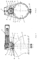
- the delivery line 1 according to FIGS. 1 and 2 consists of two tubes 2, 3 joined into one another.
- the inner tube 2 is made of a highly hardened material and is surrounded on its outer periphery by an outer tube 3.
- the thermal load during insertion of the recess 4 is controlled so that the hardness of the inner tube 2 is not changed.
- the recess 4 is designed with such high precision that the base 6 forming the lower part of the bypass valve 5 fits into the recess 4 with a positive fit and as tight as possible without play.
- the front, projecting into the inner tube 2 end face of the base 6 must be flush with the inner circumference of the inner tube 2. There must be no projections, recesses or other flow interruptions.
- the pocket 15 becomes flatter the larger the diameter of the delivery line 1 is.
- a check valve 7 is arranged in a conventional manner. It is important, however, that the base 6 also consists of a highly hardened material so that its surfaces facing the inner tube 2 can not be damaged by abrasion.
- valve disk of the check valve 7 is made of a hardened material.
- the valve body 8 of the bypass valve 5 is connected to the base 6 in a conventional manner.
- a ring-encircling seal 13 is arranged radially inside the valve carrier 9, sealingly seated on the base 6 with an associated flange enlarged diameter.
- valve carrier 9 forms a fitting to the outer circumference of the outer tube 3 saddle 10, on which a further annular seal 14 is arranged.
- the entire structure is attached to a, the entire conveyor line 1 surrounding clamp 11, which is tightened with a screw 12.
Landscapes
- Engineering & Computer Science (AREA)
- Mechanical Engineering (AREA)
- Air Transport Of Granular Materials (AREA)
- Sliding Valves (AREA)
Claims (16)
- Dispositif pour l'acheminement pneumatique à vitesse réduite d'abrasifs en vrac, comprenant une conduite d'acheminement (1) formée de deux tubes (2, 3) emboîtés axialement l'un dans l'autre, à savoir un tube intérieur (2) situé radialement à l'intérieur et un tube extérieur (3) situé radialement à l'extérieur (3), le tube intérieur (2) présentant une dureté mécanique supérieure à celle du tube extérieur (3), l'intérieur de la conduite d'acheminement (1) étant apte à être relié par une soupape de dérivation (5) à une conduite externe ou à un récipient externe de manière étanche à l'air, et la soupape de dérivation (5) présentant une tête de clapet antiretour (7) qui s'applique de manière étanche dans un socle (6),
caractérisé en ce que le socle (6) de la soupape de dérivation (5) est introduit quasiment sans jeu et par complémentarité de forme dans un creux (4) qui traverse les deux tubes (2, 3), et il est prévu une étanchéité pneumatique entre l'enveloppe extérieure du socle (6) et l'intérieur de la conduite d'acheminement (1), à l'extérieur du creux (4), et en ce que les côtés frontaux du socle (6) et de la tête de clapet antiretour (7) qui sont tournés vers l'intérieur de la conduite d'acheminement (1) sont trempés et se terminent au moins partiellement au ras de l'enveloppe intérieure du tube intérieur (2), mais ne pénètrent pas à l'intérieur de la conduite d'acheminement (1). - Dispositif selon la revendication 1, caractérisé en ce que la soupape de dérivation (5) est prévue pour l'introduction de matières de charge comme par exemple des fibres de verre.
- Dispositif selon la revendication 1 ou 2, caractérisé en ce que le creux (4) est à peu près perpendiculaire à l'axe longitudinal des tubes (2, 3).
- Dispositif selon les revendications 1 à 3, caractérisé en ce que le tube intérieur (2) et le tube extérieur (3) présentent des axes longitudinaux coaxiaux ou parallèles.
- Dispositif selon les revendications 1 à 4, caractérisé en ce que le tube intérieur (2) est trempé et le tube extérieur (3) présente une dureté normale.
- Dispositif selon les revendications 1 à 5, caractérisé en ce que l'étanchéité entre l'enveloppe extérieure du socle (6) et l'intérieur de la conduite d'acheminement (1) est réalisée à l'aide d'un joint (13) qui est posé directement sur la surface latérale extérieure du tube extérieur (3).
- Dispositif selon les revendications 1 à 5, caractérisé en ce que l'étanchéité entre l'enveloppe extérieure du socle (6) et l'intérieur de la conduite d'acheminement (1) est réalisée à l'aide d'un joint (13) qui est posé sur un support de soupape (9) lui-même posé par l'intermédiaire d'un autre joint (14) sur la surface latérale extérieure du tube extérieur (3).
- Dispositif selon la revendication 7, caractérisé en ce que le support de soupape (9) s'applique avec sa pièce d'appui (10) au ras de la surface latérale extérieure du tube extérieur (3) et le joint circulaire (14) est disposé dans la zone de la pièce d'appui (10).
- Dispositif selon la revendication 7 ou 8, caractérisé en ce que le joint circulaire (13) se trouve entre deux collerettes circulaires du socle (6) et du support de soupape (9) qui s'étendent à peu près axialement par rapport à l'axe longitudinal de la conduite d'acheminement (1).
- Dispositif selon les revendications 1 à 9, caractérisé en ce que la soupape de dérivation (5) est fixée de manière amovible à la conduite d'acheminement (1).
- Dispositif selon la revendication 10, caractérisé en ce que la soupape de dérivation (5) est fixée à la conduite d'acheminement (1) grâce à un collier de serrage (11) qui entoure sur sa circonférence toute la conduite d'acheminement (1) et une partie au moins de la soupape (5).
- Dispositif selon les revendications 1 à 11, caractérisé en ce que la vitesse pour l'acheminement des abrasifs en vrac à vitesse réduite dans la conduite (1) est inférieure à 10 m/s.
- Dispositif selon les revendications 1 à 12, caractérisé en ce que le creux (4) prévu dans le tube extérieur (3) et le tube intérieur (2) est réalisé à l'aide d'un jet d'eau à haute pression ou d'un laser, avec une faible contrainte thermique.
- Dispositif selon les revendications 1 à 13, caractérisé en ce que le côté frontal du socle (6) et le côté frontal de la tête de clapet antiretour (7) se trouvent, vus en section transversale, uniquement à l'intérieur de la matière du tube intérieur (2) et ne pénètrent pas dans la matière du tube extérieur (3).
- Dispositif selon les revendications 1 à 14, caractérisé en ce que la forme du côté frontal du socle (6) qui pénètre dans la conduite d'acheminement (1) est adaptée à la forme de l'enveloppe intérieure du tube intérieur (2), et a donc une forme partiellement circulaire, en section transversale de la conduite (1), ce qui ne forme pas de poche (15).
- Dispositif selon les revendications 1 à 15, caractérisé en ce que le tube intérieur trempé (2) et les côtés frontaux trempés du socle (6) et de la tête de soupape (7) ont à peu près la même dureté mécanique.
Applications Claiming Priority (2)
| Application Number | Priority Date | Filing Date | Title |
|---|---|---|---|
| DE10338853 | 2003-08-20 | ||
| DE2003138853 DE10338853B4 (de) | 2003-08-20 | 2003-08-20 | Vorrichtung zum Fördern von abrasiven Schüttgütern |
Publications (3)
| Publication Number | Publication Date |
|---|---|
| EP1508542A2 EP1508542A2 (fr) | 2005-02-23 |
| EP1508542A3 EP1508542A3 (fr) | 2005-03-23 |
| EP1508542B1 true EP1508542B1 (fr) | 2006-10-11 |
Family
ID=34042255
Family Applications (1)
| Application Number | Title | Priority Date | Filing Date |
|---|---|---|---|
| EP20040019651 Expired - Lifetime EP1508542B1 (fr) | 2003-08-20 | 2004-08-19 | Dispositif pour transporter des produits abrasifs en vrac |
Country Status (2)
| Country | Link |
|---|---|
| EP (1) | EP1508542B1 (fr) |
| DE (2) | DE10338853B4 (fr) |
Families Citing this family (1)
| Publication number | Priority date | Publication date | Assignee | Title |
|---|---|---|---|---|
| AT505872B1 (de) | 2007-10-12 | 2010-05-15 | Wittmann Kunststoffgeraete | Materialabscheider für fördersysteme |
Family Cites Families (7)
| Publication number | Priority date | Publication date | Assignee | Title |
|---|---|---|---|---|
| DE758917C (de) * | 1940-09-15 | 1954-06-21 | Daimler Benz Ag | Sicherheitsventil mit metallischen, konischen Dichtungsflaechen fuer Druckbehaelter |
| DE1018826B (de) * | 1956-05-11 | 1957-11-07 | Gewerkschaft Reuss | Blasversatzrohr od. dgl. |
| DE2737536C2 (de) * | 1977-08-19 | 1979-07-12 | Waeschle Maschinenfabrik Gmbh, 7980 Ravensburg | Anlage zum pneumatischen Fördern von Schüttgütern |
| US4313699A (en) * | 1980-01-31 | 1982-02-02 | Dynamic Air Inc. | Quick mount high pressure booster valves |
| DE3435907A1 (de) * | 1984-09-29 | 1986-04-10 | AVT Anlagen- und Verfahrenstechnik GmbH, 7981 Vogt | Verfahren und einrichtung zum pneumatischen und hydraulischen transport von feststoffen durch rohrleitungen |
| DE3437560A1 (de) * | 1984-10-12 | 1986-04-17 | Wäschle Maschinenfabrik GmbH, 7980 Ravensburg | Anlage zum pneumatischen foerdern von schuettguetern |
| DE3722911C1 (de) * | 1987-07-10 | 1988-09-29 | Waeschle Maschf Gmbh | Anlage zum pneumatischen Foerdern von Schuettguetern |
-
2003
- 2003-08-20 DE DE2003138853 patent/DE10338853B4/de not_active Expired - Fee Related
-
2004
- 2004-08-19 DE DE200450001712 patent/DE502004001712D1/de not_active Expired - Lifetime
- 2004-08-19 EP EP20040019651 patent/EP1508542B1/fr not_active Expired - Lifetime
Also Published As
| Publication number | Publication date |
|---|---|
| EP1508542A3 (fr) | 2005-03-23 |
| DE10338853A1 (de) | 2005-03-24 |
| DE10338853B4 (de) | 2005-12-15 |
| DE502004001712D1 (de) | 2006-11-23 |
| EP1508542A2 (fr) | 2005-02-23 |
Similar Documents
| Publication | Publication Date | Title |
|---|---|---|
| EP2179949A2 (fr) | Fermeture à accouplement ainsi que module de fixation et dispositif d'accrochage, chacun comportant ladite fermeture à accouplement | |
| DE29504332U1 (de) | Rohr zum Feststofftransport | |
| DE102007051436A1 (de) | Verbindungssystem für doppelwandige Rohre | |
| DE4221175A1 (de) | Verbindungssystem für Rohrleitungen | |
| DE3206570C2 (fr) | ||
| DE2801378C2 (de) | Rohrleitungsmolch | |
| EP1508542B1 (fr) | Dispositif pour transporter des produits abrasifs en vrac | |
| AT390779B (de) | Anlage zum pneumatischen foerdern von schuettguetern | |
| DE102013003401A1 (de) | Flachdichtung für Flanschverbindungen | |
| DE10100128A1 (de) | Anordnung zum Verbinden von zwei Rohren | |
| DE3719585A1 (de) | Loesbare sowie nichtloesbare dichte verbindung zweier benachbarter rohrleitungen | |
| EP1635094B1 (fr) | Vanne | |
| DE4207029A1 (de) | Foerderrohrleitung fuer schuettgut mit schallschutz | |
| DE60221513T2 (de) | Verfahren zur herstellung eines mit flansch versehenen elements und ein mit flansch versehenes element | |
| DE2933695A1 (de) | Winkelbeweglicher rollbalg, insbesondere zur abdichtung von drehgelenkkupplungen | |
| EP2843283A1 (fr) | Système de convoyeur de succion | |
| EP1647507B1 (fr) | Dispositif de transport de matières solides dans un conduit | |
| EP0741847B1 (fr) | Corps d'appareil de robinetterie | |
| DE19855795B4 (de) | Schneidringverschraubung für Druckmittel-Rohrleitungen | |
| EP0077058A1 (fr) | Robinet à boisseau sphérique | |
| DE19749142A1 (de) | Absperrarmatur mit einem drehbeweglichen Absperrglied und einem diesem zugeordneten metallischen Sitzring | |
| DE4318831C2 (de) | Kupplungsvorrichtung für Rohre | |
| DE828095C (de) | Rohr zur Foerderung stueckigen Gutes, insbesondere Blasversatz- und Spuelversatzrohr | |
| EP1215436A2 (fr) | Racleur pour conduite | |
| DE3138355A1 (de) | Armatur fuer ein aus zwei metallrohren bestehendes leitungsrohr |
Legal Events
| Date | Code | Title | Description |
|---|---|---|---|
| PUAI | Public reference made under article 153(3) epc to a published international application that has entered the european phase |
Free format text: ORIGINAL CODE: 0009012 |
|
| PUAL | Search report despatched |
Free format text: ORIGINAL CODE: 0009013 |
|
| AK | Designated contracting states |
Kind code of ref document: A2 Designated state(s): AT BE BG CH CY CZ DE DK EE ES FI FR GB GR HU IE IT LI LU MC NL PL PT RO SE SI SK TR |
|
| AX | Request for extension of the european patent |
Extension state: AL HR LT LV MK |
|
| AK | Designated contracting states |
Kind code of ref document: A3 Designated state(s): AT BE BG CH CY CZ DE DK EE ES FI FR GB GR HU IE IT LI LU MC NL PL PT RO SE SI SK TR |
|
| AX | Request for extension of the european patent |
Extension state: AL HR LT LV MK |
|
| 17P | Request for examination filed |
Effective date: 20050618 |
|
| AKX | Designation fees paid |
Designated state(s): BE DE FR IT NL |
|
| GRAP | Despatch of communication of intention to grant a patent |
Free format text: ORIGINAL CODE: EPIDOSNIGR1 |
|
| GRAS | Grant fee paid |
Free format text: ORIGINAL CODE: EPIDOSNIGR3 |
|
| GRAA | (expected) grant |
Free format text: ORIGINAL CODE: 0009210 |
|
| AK | Designated contracting states |
Kind code of ref document: B1 Designated state(s): BE DE FR IT NL |
|
| PG25 | Lapsed in a contracting state [announced via postgrant information from national office to epo] |
Ref country code: IT Free format text: LAPSE BECAUSE OF FAILURE TO SUBMIT A TRANSLATION OF THE DESCRIPTION OR TO PAY THE FEE WITHIN THE PRESCRIBED TIME-LIMIT;WARNING: LAPSES OF ITALIAN PATENTS WITH EFFECTIVE DATE BEFORE 2007 MAY HAVE OCCURRED AT ANY TIME BEFORE 2007. THE CORRECT EFFECTIVE DATE MAY BE DIFFERENT FROM THE ONE RECORDED. Effective date: 20061011 Ref country code: NL Free format text: LAPSE BECAUSE OF FAILURE TO SUBMIT A TRANSLATION OF THE DESCRIPTION OR TO PAY THE FEE WITHIN THE PRESCRIBED TIME-LIMIT Effective date: 20061011 |
|
| REF | Corresponds to: |
Ref document number: 502004001712 Country of ref document: DE Date of ref document: 20061123 Kind code of ref document: P |
|
| NLV1 | Nl: lapsed or annulled due to failure to fulfill the requirements of art. 29p and 29m of the patents act | ||
| EN | Fr: translation not filed | ||
| PLBE | No opposition filed within time limit |
Free format text: ORIGINAL CODE: 0009261 |
|
| STAA | Information on the status of an ep patent application or granted ep patent |
Free format text: STATUS: NO OPPOSITION FILED WITHIN TIME LIMIT |
|
| 26N | No opposition filed |
Effective date: 20070712 |
|
| BERE | Be: lapsed |
Owner name: MOTAN MATERIALS HANDLING G.M.B.H. Effective date: 20070831 |
|
| PG25 | Lapsed in a contracting state [announced via postgrant information from national office to epo] |
Ref country code: FR Free format text: LAPSE BECAUSE OF FAILURE TO SUBMIT A TRANSLATION OF THE DESCRIPTION OR TO PAY THE FEE WITHIN THE PRESCRIBED TIME-LIMIT Effective date: 20070601 |
|
| PG25 | Lapsed in a contracting state [announced via postgrant information from national office to epo] |
Ref country code: BE Free format text: LAPSE BECAUSE OF NON-PAYMENT OF DUE FEES Effective date: 20070831 |
|
| PG25 | Lapsed in a contracting state [announced via postgrant information from national office to epo] |
Ref country code: FR Free format text: LAPSE BECAUSE OF FAILURE TO SUBMIT A TRANSLATION OF THE DESCRIPTION OR TO PAY THE FEE WITHIN THE PRESCRIBED TIME-LIMIT Effective date: 20061011 |
|
| PGFP | Annual fee paid to national office [announced via postgrant information from national office to epo] |
Ref country code: DE Payment date: 20200824 Year of fee payment: 17 |
|
| REG | Reference to a national code |
Ref country code: DE Ref legal event code: R119 Ref document number: 502004001712 Country of ref document: DE |
|
| PG25 | Lapsed in a contracting state [announced via postgrant information from national office to epo] |
Ref country code: DE Free format text: LAPSE BECAUSE OF NON-PAYMENT OF DUE FEES Effective date: 20220301 |