EP1508545A1 - Aufzugsanlage mit belastungsabhängigem Tragmittelfixpunkt - Google Patents
Aufzugsanlage mit belastungsabhängigem Tragmittelfixpunkt Download PDFInfo
- Publication number
- EP1508545A1 EP1508545A1 EP04017606A EP04017606A EP1508545A1 EP 1508545 A1 EP1508545 A1 EP 1508545A1 EP 04017606 A EP04017606 A EP 04017606A EP 04017606 A EP04017606 A EP 04017606A EP 1508545 A1 EP1508545 A1 EP 1508545A1
- Authority
- EP
- European Patent Office
- Prior art keywords
- elevator car
- elevator
- guide rail
- support means
- suspension
- Prior art date
- Legal status (The legal status is an assumption and is not a legal conclusion. Google has not performed a legal analysis and makes no representation as to the accuracy of the status listed.)
- Granted
Links
Images


Classifications
-
- B—PERFORMING OPERATIONS; TRANSPORTING
- B66—HOISTING; LIFTING; HAULING
- B66B—ELEVATORS; ESCALATORS OR MOVING WALKWAYS
- B66B7/00—Other common features of elevators
- B66B7/06—Arrangements of ropes or cables
- B66B7/062—Belts
-
- B—PERFORMING OPERATIONS; TRANSPORTING
- B66—HOISTING; LIFTING; HAULING
- B66B—ELEVATORS; ESCALATORS OR MOVING WALKWAYS
- B66B7/00—Other common features of elevators
- B66B7/06—Arrangements of ropes or cables
- B66B7/10—Arrangements of ropes or cables for equalising rope or cable tension
Definitions
- the invention relates to an elevator system with Wippvoriques according to the preamble of claim 1 and a rocking device according to the preamble of claim 11.
- suspension means are in the range of Fixed counterweight, carry a counterweight, become an upper (drive) disc deflected and then run in the form of a loop under the elevator car through and are on the other side of the elevator car fixed.
- This fixation is also known as the cabin side Tragstofffix
- fixation in the area the counterweight as a counterweight side suspension point referred to as.
- the cabin-side suspension element fixing points to provide on a guide rail 5, the vertical guidance of an elevator car serves.
- This kind of Attachment loads the guide rail 5 and leads to a bending moment acting on the rail 5.
- Fig. 1A a variant is shown, in which the Cabin-side suspension element fixed point 1 asymmetric at the Guide rail 5 is fixed.
- the suspension means (not in FIGS. 1A to 1E) attract with a force F1 the suspension point 1. This results in a bending moment, which acts on the guide rail 5.
- a variant is shown in which a cabin-side Tragstofffixtician 2 is provided, on the one hand on the guide rail 5 and on the other hand at a point 2.1 is supported against a shaft wall.
- Advantageous in This variant is the bending moment-free force in the rail 5, on the other hand, is the fact that it is when lowering the elevator shaft, or at temperature-related Expansions of the rail 5 to a misalignment can come.
- the wall of the elevator shaft burdened by the type of suspension shown.
- Fig. 1C a variant is shown in which a cabin-side Tragstofffixtician 3 is provided, the at a Shaft wall is supported, without the guide rail. 5 to communicate.
- This type of suspension leads to a high wall load.
- the Tragstofffixtician 4 can also on one side to a Guide rail 5 and on the other side in one Wall recess 7 of the elevator shaft 6 be supported, as in Fig. 1D shown.
- the support in the wall niche 7 is form-fitting.
- An advantage of this variant is the BiegemomentMap force introduction into the rail 5, disadvantageous on the other hand, the fact that, if the Elevator shaft, or at temperature-related expansions the rail 5 can come to a misalignment.
- the wall of the elevator shaft by the type shown Suspension loaded.
- the support means fixed point 8 on both sides in Wall niches 7 of the elevator shaft 6 to be stored. It comes to no load on the guide rail 5, but the whole Load must be carried through the walls of the shaft 6.
- the luffing device requires no Support or fixation on one of the walls of a lift shaft.
- the luffing device allows one Compensation, if the suspension means minor differences in length if the design has smaller overall asymmetries should or should it over time come a different elongation of the support means should.
- a reaction - for example an emergency stop - to be triggered.
- FIG. 2 A first embodiment of a lift according to The invention is shown in FIG. 2 in a schematic perspective view shown.
- a machine room Elevator system 20 shown comprising a lift shaft or "without a box”.
- the present invention relates to a machine room less Elevator installation 20, the elevator car 13 and at least a first guide rail 15 for vertically guiding the Elevator car 13 includes.
- the first guide rail 15 is shown in Fig. 2 only by a dashed line.
- It two support means 22 are provided, which are substantially parallel to each other.
- the front suspension means with 22.1 and the rear suspension means 22.2 where this for better distinction is necessary.
- At the cabin side End of the support means 22 are the same in the first area Tragstofffixand 29 via a rocker 30 at the Guide rail 15 fixed.
- Each of the support means 22.1 and 22.2 undermines the elevator car 13, wraps around a Traction sheave 12, which before a drive (not in Fig.
- the suspension element 22 carries the counterweight 18 in that the support means 22 to counterweight rollers 21 revolve and at the counterweight end in the Area second support means fixed points 28 are fixed.
- the Slinging of the elevator car 13 takes place at the shown embodiment with Kabinentragrollen 17.1 and Guide rollers 17.2, which are each designed in pairs.
- the said rocker device 30 has two arms and is indicated in Fig. 2 only schematically. It is mechanical like that attached to the guide rail 15 that a rocking motion the rocking device 30 is possible about an axis in the Substantially perpendicular to the guide rail 15 extends. On Each of the two arms of the rocker 30 is ever one the suspension center points provided.
- the rocker device 30 allows for uneven load on the two suspension elements 22.1 and 22.2 a rocking motion by a length compensation is done automatically. Is it coming to a Tragstoffbruch one of the support means, so the luffing device 30 suddenly loaded unbalanced what a Rocking movement of the rocker 30 in one direction caused.
- This rocking motion can either by means of a Button or a non-contact switch detected be used to interrupt the driving of the elevator system, or the luffing device 30 can mechanically into a Speed limiter intervene to stop a brake trigger. It may also alternatively or additionally Warning signal to be triggered. More details on this will be described later.
- FIG. 3 remove Details of a similar embodiment are shown in FIG. 3 remove.
- the reference numeral 11 is a
- the drive 10 has an on a traction sheave shaft 25th acting drive shaft 24, which is parallel to the counterweight side Wall 13.1 of the elevator car 13 aligned is and carries at least one traction sheave 26.
- the drive 10 and the traction sheave shaft 25 with at least one Traction sheave 12 are mounted on a machine carrier 23, located on the two counterweight guide rails 18.1 supported and mechanically connected to these. It is also possible on the drive 10 and the above elements or to be attached to the guide rail 15, the left of the elevator car 13 is arranged. Alternatively you can Drive 10 and the said elements on the counterweight guide rails 18.1 and the guide rails 15 supported his.
- a brake unit 27 be arranged, the braking of the elevator car 13th allows.
- the brake unit 27 is in Fig. 3 only by Dashed lines indicated because they are behind the drive 10th sitting.
- Fig. 3 are the counterweight-side suspension element fixing points 28 of the suspension element 22 attached in the area below the machine carrier 23.
- this attachment is done by means of screws about which the position of the support means end individually can be adjusted. This can be done an adjustment be that allows the luffing device 30 in a predefined location, for example a horizontal position too bring.
- the two support means 22 (22.1 and 22.2) are substantially parallel to each other.
- the suspension elements 22 run along the left Side wall 13.1 of the elevator car 13 down and then at least partially around the cabin roll 17.1 around guided. This type of suspension is called as Underslinging.
- the support means 22 are guided upward, where each of the Supporting means 22 in the area of the cabin-side suspension element fixing points 29 is attached to an arm of a rocker 30.
- suspension is synonymous with any kind of To understand ropes and means that are suitable for Elevator car 13 and the counterweight 18 to carry and to move.
- the suspension means are Flat or V-ribbed belt. It may be related to the invention but also steel or plastic ropes with round cross-section used as a suspension element.
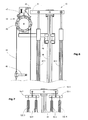
- Fig. 4 is a specific embodiment of the inventive Rocker 30 shown.
- the rocker device 30 includes a first arm 30.1 and a second arm 30.2.
- these arms 30.1 and 30.2 are preferably not necessarily symmetrical with respect to a rotation axis 30.3 arranged, in the example shown perpendicular to the plane of the drawing runs.
- the axis of rotation 30.3 is on or on the Guide rail 15 stored.
- Each of the two arms 30.1 and 30.2 has attachment points 30.4 and 30.5, the Attachment of the support means 22.1 and 22.2 serve. Important is only that the attachment points 30.4 and 30.5 are arranged symmetrically with respect to the axis of rotation 30.3.
- the attachment of the Support means 22.1 and 22.2 by means of rods 31.1, 31.2, the in the upper part are designed as eyelets 31.3, 31.4.
- the Eyelets 31.3, 31.4 sit on axles 30.7, 30.8, or the like. They are clamping or screwing 22.3 and 22.4 provided, which are the ends of flat or V-ribbed belts 22.1, 22.2 record and fix.
- the support means to V-ribbed belts 22.1, 22.2 as you can see from the parallel can recognize running lines, which the ribs of the To represent belts.
- the round bars 31.1, 31.2 can be designed as threaded spindles to turn by turning Round bars 31.1, 31.2 the position of the arms of the rocking device 30 to be able to adjust.
- the rocker 30 is also in a position shown that it occupies when the support means 22.1 shorter is as the support means 22.2. This position of the rocker 30 is shown by dashed lines.
- the Unequal length of the support means 22.1, and 22.2 results a rocking movement about the axis 30.3, the ß by the angle can be quantified.
- On the guide rail 15 can optionally a stop 36 for the arms of the rocking device 30th be provided.
- an optional Device 32 shown in a rocking motion, the over exceeds a limit, the elevator system 20 turns off and / or the elevator car (13) brakes and / or a warning signal triggers.
- This device 32 will be simplified herein referred to as a limiting device. It can become Example to act a button, the two contacts electrically conductively connects as long as the rocker 30th is in an angular range that is smaller than ⁇ ⁇ .
- the tipping device 30 retards the angular range ⁇ ⁇ above or below - for example, due to different Wearer or when breaking a suspension - so the button interrupts the electrically conductive connection.
- the button can be part of the usual be present at elevators existing safety circuit.
- a button can also be a berckenungsokoer Switch can be used.
- a berckenungsokoer Switch can be used.
- a tilt sensor or tilt switch used in the area of the rocker 30 so is arranged that when a too large Deflection of the rocker 30 triggered a reaction becomes.
- FIG. 5 shows a section that runs through an inventive rocker device 30 and guide rail 15.
- Fig. 5 serves to explain the geometric arrangement of a preferred embodiment.
- the luffing device 30 is arranged and designed so that it is supported on the centroid P of the guide rail 15 so that a connecting line X between two support means extends through this centroid.
- the distance a of the two axes 30.7 and 30.8, which symbolize the force application positions of the support means, from the point P is the same for both arms 30.1 and 30.2.
- the two axes 30.7 and 30.8 are indicated in Fig. 5 by dashed lines.
- the connection of the support means with the arms of the rocking device is designed according to the invention so that it allows at least small rotational movements.
- the luffing device can perform corresponding rocking movements of the different support means elongation.
- the rotational movement can be achieved by the attachment of the support means on the arms 30.1, 30.2 of the luffing device 30 by means of eyelets 31.3, 31.4 and axes 30.7, 30.8 is executed.
- secondary rockers can also be provided, which are connected via axes with the arms 30.1, 30.2 of the luffing device. These secondary rockers can perform small rocking movements with respect to the rocker.
- Another embodiment is characterized in that the rods 31.1, 31.2 are flexible and connected at their upper ends in the region of the eyelets fixed to the arms of the Wippvorraum. The flexibility of the rods 31.1, 31.2 gives the necessary freedom of movement.
- FIG. 6 Shown in Fig. 6 is a schematic arrangement which, similar to the limiting device 32, triggers a response when the rocking motion exceeds a threshold. If the deflection of the arms of the luffing device 40 by large differences in length of the support means 42.1, 42.2 or due to a Tragstoffbruchs exceeds a certain limit, the blocking pendulum 47 of a pendulum speed limiter 43 of known type is forced into blocking position by the arm 41. Such speed limiters 43 are used to limit the speed of elevator cars.
- a closed rope 44 namely a so-called speed limiter rope is used as auxiliary rope.
- This speed limiter cable 44 travels around a pulley 45 of the speed limiter 43 mounted in the elevator shaft at the top and around a tension pulley mounted at the bottom in the hoistway (not shown in FIG. 6).
- the overspeed governor 44 is connected to the elevator car via a catcher trip lever 46, which is not shown in FIG. If the speed of the elevator car exceeds a certain limit speed, then the pulley 45 of the speed limiter 43 and with it the speed limiter cable 44 are blocked by the blocking pendulum 47, whereby the braked speed limiter cable 44 actuates the safety gear release lever 46 moving with the moving elevator car so that triggers a mounted on the elevator car safety device triggers.
- the safety gear can be triggered when the deflection of the arms of the rocker 40 by large differences in length of the support means 42.1, 42.2 or due to a Tragstoffbruchs exceeds a certain limit.
- the arm 41 of the rocker 40 actuates either directly or via a lever 50, the blocking pendulum 47 and thereby causes the above-described blocking of the speed limiter 43 and the triggering of the safety brake.
- the rocker 40 is supported on the guide rail 48 from.
- the speed limiter 43 can be carried by the guide rail 48 via a mechanical connection 49.
- the limiting device 32 (FIG. 4) can also be electrical, e.g. via a solenoid, the speed limiter Trigger according to FIG. 6.
- the luffing device 30 is mounted so that its rocking movements are slightly damped. Thus, short load fluctuations, for example due to vibrations of the elevator car 13, can be damped. Additionally or alternatively, means may be provided which as Stop for the luffing device 30; 40 serve. In Fig. 6 serving for this purpose adjustable stop screws 60 are shown.
- Embodiments with 4, 6 or more support means 52.1 - 52.4 can be designed so that in each case two of the suspension means 52.1, 52.2 and 52.3, 52.4 in pairs on a luffing device 55.1 and 55.2 are attached. Two such rockers 55.1 and 55.2 are then together again at a parent Rocker 55.3 suspended, as shown schematically in Fig. 7 is shown. The entire rocking device is supported turn on the guide rail 51 from.
- Another embodiment is characterized in that the support means also on the counterweight side at the are fixed there guide rail.
Landscapes
- Lift-Guide Devices, And Elevator Ropes And Cables (AREA)
Abstract
Description
Es zeigen
- Fig. 1A bis 1E
- verschiedene Varianten bekannter Aufhängungen für ein Tragmittel;
- Fig. 2
- eine schematische Ansicht einer ersten Aufzugsanlage gemäss Erfindung;
- Fig. 3
- eine schematische Schnittansicht einer weiteren Aufzugsanlage gemäss Erfindung;
- Fig. 4
- Details einer Wippvorrichtung gemäss Erfindung;
- Fig. 5
- eine Schnittdarstellung einer Wippvorrichtung gemäss Erfindung;
- Fig. 6
- eine schematische Ansicht einer Wippvorrichtung mit Begrenzungsvorrichtung, gemäss Erfindung;
- Fig. 7
- eine schematische Ansicht einer Wippvorrichtung für 4 Tragmittel, gemäss Erfindung.
Die Verbindung der Tragmittel mit den Armen der Wippvorrichtung ist gemäss Erfindung so ausgeführt, dass sie zumindest kleine Drehbewegungen zulässt. Dies ist notwendig, da die Tragmittel jeweils vertikal nach unten gerichtet sind, die Wippvorrichtung jedoch der unterschiedlichen Tragmittellängung entsprechende Wippbewegungen ausführen kann. Wie in Fig. 4 gezeigt, kann die Drehbewegbarkeit erreicht werden, indem die Befestigung der Tragmittel an den Armen 30.1, 30.2 der Wippvorrichtung 30 mittels Ösen 31.3, 31.4 und Achsen 30.7, 30.8 ausgeführt ist. Anstatt der Ösen, können aber auch Sekundärwippen vorgesehen werden, die über Achsen mit den Armen 30.1, 30.2 der Wippvorrichtung verbunden sind. Diese Sekundärwippen können kleine Wippbewegungen in Bezug auf die Wippvorrichtung ausführen. Eine andere Ausführungsform zeichnet sich dadurch aus, dass die Stäbe 31.1, 31.2 flexibel ausgeführt und an ihren oberen Enden im Bereich der Ösen fest mit den Armen der Wippvorrichtung verbunden sind. Die Flexibilität der Stäbe 31.1, 31.2 gibt die notwendige Bewegungsfreiheit.
Solche Geschwindigkeitsbegrenzer 43 werden zur Begrenzung der Geschwindigkeit von Aufzugskabinen eingesetzt. Hierbei wird als Hilfsseil ein geschlossenes Seil 44, nämlich ein so genanntes Geschwindigkeitsbegrenzerseil verwendet. Dieses Geschwindigkeitsbegrenzerseil 44 läuft um eine Seilrolle 45 des oben in dem Aufzugsschacht angebrachten Geschwindigkeitsbegrenzers 43 und um eine unten im Aufzugsschacht angebrachte Spannrolle (nicht in Fig. 6 gezeigt). Das Geschwindigkeitsbegrenzerseil 44 ist über einen Fangvorrichtungs-Auslösehebel 46 mit der Aufzugskabine verbunden, die nicht in Fig. 6 gezeigt ist. Übersteigt die Geschwindigkeit der Aufzugskabine eine gewisse Grenzgeschwindigkeit, so wird durch das Blockierpendel 47 in bekannter Weise die Seilrolle 45 des Geschwindigkeitsbegrenzers 43 und mit dieser das Geschwindigkeitsbegrenzerseil 44 blockiert, wodurch das gebremste Geschwindigkeitsbegrenzerseil 44 den sich mit der fahrenden Aufzugskabine bewegenden Fangvorrichtungs-Auslösehebel 46 betätigt und damit eine an der Aufzugskabine angebrachte Fangvorrichtung auslöst.
Wie in Fig. 6 gezeigt, stützt sich die Wippvorrichtung 40 auf der Führungsschiene 48 ab. Der Geschwindigkeitsbegrenzer 43 kann über eine mechanische Verbindung 49 von der Führungsschiene 48 getragen werden.
Anschlag für die Wippvorrichtung 30; 40 dienen. In Fig. 6 sind diesem Zweck dienende einstellbare Anschlagschrauben 60 gezeigt.
Claims (13)
- Aufzugsanlage (20) mitdadurch gekennzeichnet, dass eine Wippvorrichtung (30; 40) mit zwei Armen (30.1, 30.2) an der Führungsschiene (15; 48; 51) befestigt ist, die so ausgebildet ist, dass eine Wippbewegung der Arme (30.1, 30.2) möglich ist, wobei an jedem der beiden Arme (30.1, 30.2) ein der ersten Seite der Aufzugskabine zugeordneter Tragmittelfixpunkte (29) vorgesehen ist und die Wippvorrichtung (30; 40) durch die Wippbewegung ungleichmässige Belastung der beiden Tragmittel (22; 42.1, 42.2; 52.1 - 52.4) verhindert.einer Aufzugskabine (13),einer auf einer ersten Seite der Aufzugskabine vorhandenen Führungsschiene (15; 48; 51) zum vertikalen Führen der Aufzugskabine (13)mehreren im Wesentlichen parallel zueinander verlaufenden Tragmitteln (22; 42.1, 42.2; 52.1 - 52.4), die ein auf der ersten oder der dieser gegenüberliegenden Seite der Aufzugskabine (13) installiertes Gegengewicht (18) tragen und die Aufzugskabine (13) unterschlingen, wobei jedes der Tragmittel (22; 42.1, 42.2; 52.1 - 52.4) mit einem Ende auf der ersten Seite und mit dem anderen Ende auf der gegenüberliegenden Seite der Aufzugskabine an dort jeweils vorhandenen Tragmittelfixpunkten (28, 29) befestigt ist,
- Aufzugsanlage (20) nach Anspruch 1, dadurch gekennzeichnet, dass eine zweite Führungsschiene (15) zum vertikalen Führen der Aufzugskabine (13) vorhanden ist, die vorzugsweise einen Antrieb 10 abstützt, der seitlich oberhalb der Aufzugskabine (13) angeordnet ist.
- Aufzugsanlage (20) nach Anspruch 2, dadurch gekennzeichnet, dass die Tragmittel (22.1, 22.2; 42.1, 42.2; 52.1 - 52.4) im Wesentlichen symmetrisch in Bezug auf eine sich zwischen der ersten und zweiten Führungsschiene (15; 48; 51) erstreckenden Ebene ausgelegt sind.
- Aufzugsanlage (20) nach Anspruch 2, dadurch gekennzeichnet, dass Flach- oder Keilrippenriemen als Tragmittel (22; 42.1, 42.2; 52.1 - 52.4) dienen, wobei die Tragmittel die Aufzugskabine (13) im Form einer 2:1-Unterschlingung tragen.
- Aufzugsanlage (20) nach Anspruch 2, dadurch gekennzeichnet, dass eine gradzahlige Gesamtzahl an Tragmitteln (22; 42.1, 42.2; 52.1 - 52.4) eingesetzt wird, wobei die Hälfte der Gesamtzahl an Tragmitteln (22; 42.1, 42.2; 52.1 - 52.4) auf einer Seite und die andere Hälfte der Gesamtzahl an Tragmitteln (22; 42.1, 42.2; 52.1 - 52.4) auf der anderen Seite der ersten und zweiten Führungsschiene (15; 48; 51) angeordnet sind.
- Aufzugsanlage (20) nach Anspruch 1, dadurch gekennzeichnet, dass das Gegengewicht (18) seitlich der Aufzugskabine (13) durch zwei Gegengewichts-Führungsschienen (18.1) geführt wird.
- Aufzugsanlage (20) nach Anspruch 1, dadurch gekennzeichnet, dass ein Anschlag (36) vorgesehen ist, um die Wippbewegung mechanisch zu begrenzen.
- Aufzugsanlage (20) nach einem der Ansprüche 2, 3 oder 4,
dadurch gekennzeichnet, dass die Wippvorrichtung (30; 40) derart auf oder an einem oberen Ende der ersten Führungsschiene (15; 48; 51) abgestützt ist, dass vertikal abwärts gerichteten Zugkräfte (F1, F2), die durch die Tragmittel (22.1, 22.2) auf die Wippvorrichtung (30; 40) wirken, im Bereich des Flächenschwerpunkts (P) des Querschnitts der ersten Führungsschiene (15; 48; 51) in diese eingeleitet werden. - Aufzugsanlage (20) nach einem der Ansprüche 2 bis 6,
dadurch gekennzeichnet, dass die Wippvorrichtung (30; 40) mit einer Begrenzungsvorrichtung (32; 41) verbunden ist, die bei einer Wippbewegung, die über einen Grenzwert hinausgeht, den Antrieb 10 der Aufzugsanlage (20) abstellt und/oder die Aufzugskabine (13) bremst und/oder ein Warnsignal auslöst. - Aufzugsanlage (20) nach Anspruch 9, dadurch gekennzeichnet, dass die Begrenzungsvorrichtung (41) mechanisch oder elektrisch mit einem Geschwindigkeitsbegrenzer (43) der Aufzugsanlage (20) in Wechselwirkung steht, um die Aufzugskabine (13) über eine Fangvorrichtung (44, 46) zu bremsen.
- Wippvorrichtung (30; 40), die dazu ausgelegt ist in einer Aufzugsanlage (20) verwendet zu werden, diedadurch gekennzeichnet, dass die Wippvorrichtung zur Montage an oder auf der Führungsschiene (15; 48; 51) vorbereitet ist, und zwei Arme (30.1, 30.2) aufweist, die Befestigungsmittel (22.3, 22.4, 30.7, 30.8, 31.1, 31.2, 31.3, 31.4) zum bewegbaren Befestigen eines Tragmittels (22.1, 22.2) aufweisen, welche das Ende der Tragmittel (22.1, 22.2) aufnehmen und fixieren und wobei die Befestigungsmittel (22.3, 22.4, 30.7, 30.8, 31.1, 31.2, 31.3, 31.4) symmetrisch in Bezug auf eine Drehachse (30.3) angeordnet sind.eine Aufzugskabine (13),mindestens eine auf einer ersten Seite der Aufzugskabine angeordnete erste Führungsschiene (15; 48; 51) zum vertikalen Führen der Aufzugskabine (13), undmehrere im Wesentlichen parallel zueinander verlaufende Tragmittel (22; 42.1, 42.2; 52.1 - 52.4) aufweist, die ein auf der ersten Seite der Aufzugskabine (13) installiertes Gegengewicht (18) tragen und die Aufzugskabine (13) unterschlingen, wobei jedes der Tragmittel (22; 42.1, 42.2; 52.1 - 52.4) mit einem Ende auf der ersten Seite und mit dem anderen Ende auf der gegenüberliegenden Seite der Aufzugskabine an dort jeweils vorhandenen Tragmittelfixpunkten (28, 29) befestigt ist,
- Wippvorrichtung (30; 40) nach Anspruch 11, dadurch gekennzeichnet, dass sie eine Begrenzungsvorrichtung (41) umfasst, die mechanisch oder elektrisch mit einem Geschwindigkeitsbegrenzer (43) koppelbar ist, um einen Antrieb 10 der Aufzugsanlage (20) abzustellen und/oder die Aufzugskabine (13) zu bremsen, falls die Wippvorrichtung (40) eine Wippbewegung macht, die über einen Grenzwert hinausgeht.
- Wippvorrichtung (30; 40) nach Anspruch 11, dadurch gekennzeichnet, dass die Befestigungsmittel Klemm- oder Schraubvorrichtungen (22.3, 22.4) umfassen.
Priority Applications (1)
| Application Number | Priority Date | Filing Date | Title |
|---|---|---|---|
| EP04017606.7A EP1508545B1 (de) | 2003-08-12 | 2004-07-26 | Aufzugsanlage mit belastungsabhängigem Tragmittelfixpunkt |
Applications Claiming Priority (3)
| Application Number | Priority Date | Filing Date | Title |
|---|---|---|---|
| EP03405591A EP1510493A1 (de) | 2003-08-12 | 2003-08-12 | Aufzugsanlage mit belastungsabhängigem Tragmittelfixpunkt |
| EP03405591 | 2003-08-12 | ||
| EP04017606.7A EP1508545B1 (de) | 2003-08-12 | 2004-07-26 | Aufzugsanlage mit belastungsabhängigem Tragmittelfixpunkt |
Publications (2)
| Publication Number | Publication Date |
|---|---|
| EP1508545A1 true EP1508545A1 (de) | 2005-02-23 |
| EP1508545B1 EP1508545B1 (de) | 2015-12-23 |
Family
ID=34066524
Family Applications (1)
| Application Number | Title | Priority Date | Filing Date |
|---|---|---|---|
| EP04017606.7A Expired - Lifetime EP1508545B1 (de) | 2003-08-12 | 2004-07-26 | Aufzugsanlage mit belastungsabhängigem Tragmittelfixpunkt |
Country Status (1)
| Country | Link |
|---|---|
| EP (1) | EP1508545B1 (de) |
Cited By (7)
| Publication number | Priority date | Publication date | Assignee | Title |
|---|---|---|---|---|
| EP3124421A1 (de) | 2015-07-28 | 2017-02-01 | Inventio AG | Tragmittelaufhängvorrichtung mit asymmetrischer wippvorrichtung für eine aufzuganlage |
| EP3124422A1 (de) | 2015-07-28 | 2017-02-01 | Inventio AG | Aufzuganlage mit ungleichmässiger lastverteilung an mehreren über eine tragmittelaufhängvorrichtung befestigten tragmitteln |
| EP3124424A1 (de) | 2015-07-28 | 2017-02-01 | Inventio AG | Tragmittelaufhängvorrichtung mit umlenkrollen aufweisender wippvorrichtung für eine aufzuganlage |
| EP3124423A1 (de) | 2015-07-28 | 2017-02-01 | Inventio AG | Tragmittelaufhängvorrichtung mit zweistufiger wippvorrichtung mit langen unteren haltearmen für eine aufzuganlage |
| CN116969369A (zh) * | 2023-09-22 | 2023-10-31 | 沈阳蓝光驱动技术有限公司 | 一种电梯曳引机制动装置 |
| EP4349760A1 (de) * | 2022-10-05 | 2024-04-10 | TK Elevator Innovation and Operations GmbH | Auswuchtvorrichtung für aufhängungsmittel |
| CN119117871A (zh) * | 2024-11-15 | 2024-12-13 | 昆山市飞鹏金属工业有限公司 | 一种电梯方向导引对重导轨架 |
Citations (2)
| Publication number | Priority date | Publication date | Assignee | Title |
|---|---|---|---|---|
| EP0987212A2 (de) * | 1998-09-14 | 2000-03-22 | Kabushiki Kaisha Toshiba | TREIBSCHEIBENAUFZUG mit Kabelkupplungen zur Befestigung von Kabelenden an Führungschienen |
| EP1123891A2 (de) * | 2000-02-09 | 2001-08-16 | Otis Elevator Company | Befestigung für Aufzugsseilende |
-
2004
- 2004-07-26 EP EP04017606.7A patent/EP1508545B1/de not_active Expired - Lifetime
Patent Citations (2)
| Publication number | Priority date | Publication date | Assignee | Title |
|---|---|---|---|---|
| EP0987212A2 (de) * | 1998-09-14 | 2000-03-22 | Kabushiki Kaisha Toshiba | TREIBSCHEIBENAUFZUG mit Kabelkupplungen zur Befestigung von Kabelenden an Führungschienen |
| EP1123891A2 (de) * | 2000-02-09 | 2001-08-16 | Otis Elevator Company | Befestigung für Aufzugsseilende |
Cited By (8)
| Publication number | Priority date | Publication date | Assignee | Title |
|---|---|---|---|---|
| EP3124421A1 (de) | 2015-07-28 | 2017-02-01 | Inventio AG | Tragmittelaufhängvorrichtung mit asymmetrischer wippvorrichtung für eine aufzuganlage |
| EP3124422A1 (de) | 2015-07-28 | 2017-02-01 | Inventio AG | Aufzuganlage mit ungleichmässiger lastverteilung an mehreren über eine tragmittelaufhängvorrichtung befestigten tragmitteln |
| EP3124424A1 (de) | 2015-07-28 | 2017-02-01 | Inventio AG | Tragmittelaufhängvorrichtung mit umlenkrollen aufweisender wippvorrichtung für eine aufzuganlage |
| EP3124423A1 (de) | 2015-07-28 | 2017-02-01 | Inventio AG | Tragmittelaufhängvorrichtung mit zweistufiger wippvorrichtung mit langen unteren haltearmen für eine aufzuganlage |
| EP4349760A1 (de) * | 2022-10-05 | 2024-04-10 | TK Elevator Innovation and Operations GmbH | Auswuchtvorrichtung für aufhängungsmittel |
| CN116969369A (zh) * | 2023-09-22 | 2023-10-31 | 沈阳蓝光驱动技术有限公司 | 一种电梯曳引机制动装置 |
| CN116969369B (zh) * | 2023-09-22 | 2024-01-09 | 沈阳蓝光驱动技术有限公司 | 一种电梯曳引机制动装置 |
| CN119117871A (zh) * | 2024-11-15 | 2024-12-13 | 昆山市飞鹏金属工业有限公司 | 一种电梯方向导引对重导轨架 |
Also Published As
| Publication number | Publication date |
|---|---|
| EP1508545B1 (de) | 2015-12-23 |
Similar Documents
| Publication | Publication Date | Title |
|---|---|---|
| EP2421785B1 (de) | Betriebszustandsüberwachung von tragmitteln in einer aufzugsanlage | |
| EP0554712B1 (de) | Seilspannsystem für Aufzüge | |
| EP1953108B1 (de) | Aufzug und Verfahren zur Überwachung dieses Aufzuges | |
| EP2560909B1 (de) | Betriebszustandsüberwachung von tragmitteln in einer aufzugsanlage | |
| EP2227429B1 (de) | Aufzugsanlage mit zwei aufzugskabinen | |
| EP1700811B1 (de) | Aufzuganlage | |
| DE19906073C2 (de) | Vorrichtung zum Verhindern unkontrollierter Beschleunigungen eines Fahrkorbs einer Aufzugsanlage | |
| WO2012004268A1 (de) | Überwachung von tragmitteln in einer aufzugsanlage | |
| EP2632839A1 (de) | Aufzuganlage | |
| EP2928805B1 (de) | Doppeldecker-aufzug mit verstellbarer interkabinendistanz | |
| DE102012016336A1 (de) | Geschwindigkeitsbegrenzer für ein Aufzugsystem | |
| EP1508545B1 (de) | Aufzugsanlage mit belastungsabhängigem Tragmittelfixpunkt | |
| EP3119713A1 (de) | Aufzug mit unterseilspannvorrichtung | |
| EP1510493A1 (de) | Aufzugsanlage mit belastungsabhängigem Tragmittelfixpunkt | |
| EP0787676A1 (de) | Sicherheitseinrichtung | |
| DE69020005T2 (de) | Luftspalteinrichtung für linearen Ringmotor. | |
| EP1918238B1 (de) | Aufzug mit zwei übereinander liegenden Aufzugskabinen in einem Schacht | |
| WO2021148456A1 (de) | Hebevorrichtung zum steuerbaren heben einer nutzlast innerhalb eines aufzugschachts | |
| DE10319731B4 (de) | Aufzug | |
| EP3227216A1 (de) | Aufzuganlage | |
| EP4452814A1 (de) | Bremsvorrichtung für eine aufzugkabine und deren verwendung in einer aufzuganlage und verfahren | |
| EP4271640B1 (de) | Aufhängevorrichtung und deren verwendung in einer aufzugsanlage und verfahren | |
| EP3578495A1 (de) | Aufzuganlage mit einer selbstspannenden seilartigen kompensationsgewichtsanordnung | |
| EP3020674B1 (de) | Servicelift | |
| DE10034511C1 (de) | Maschinenraumloser Seilaufzug |
Legal Events
| Date | Code | Title | Description |
|---|---|---|---|
| PUAI | Public reference made under article 153(3) epc to a published international application that has entered the european phase |
Free format text: ORIGINAL CODE: 0009012 |
|
| AK | Designated contracting states |
Kind code of ref document: A1 Designated state(s): AT BE BG CH CY CZ DE DK EE ES FI FR GB GR HU IE IT LI LU MC NL PL PT RO SE SI SK TR |
|
| AX | Request for extension of the european patent |
Extension state: AL HR LT LV MK |
|
| 17P | Request for examination filed |
Effective date: 20050822 |
|
| AKX | Designation fees paid |
Designated state(s): AT BE BG CH CY CZ DE DK EE ES FI FR GB GR HU IE IT LI LU MC NL PL PT RO SE SI SK TR |
|
| REG | Reference to a national code |
Ref country code: HK Ref legal event code: DE Ref document number: 1074828 Country of ref document: HK |
|
| GRAP | Despatch of communication of intention to grant a patent |
Free format text: ORIGINAL CODE: EPIDOSNIGR1 |
|
| INTG | Intention to grant announced |
Effective date: 20150716 |
|
| GRAS | Grant fee paid |
Free format text: ORIGINAL CODE: EPIDOSNIGR3 |
|
| GRAA | (expected) grant |
Free format text: ORIGINAL CODE: 0009210 |
|
| AK | Designated contracting states |
Kind code of ref document: B1 Designated state(s): AT BE BG CH CY CZ DE DK EE ES FI FR GB GR HU IE IT LI LU MC NL PL PT RO SE SI SK TR |
|
| REG | Reference to a national code |
Ref country code: GB Ref legal event code: FG4D Free format text: NOT ENGLISH |
|
| REG | Reference to a national code |
Ref country code: CH Ref legal event code: EP |
|
| REG | Reference to a national code |
Ref country code: IE Ref legal event code: FG4D Free format text: LANGUAGE OF EP DOCUMENT: GERMAN |
|
| REG | Reference to a national code |
Ref country code: AT Ref legal event code: REF Ref document number: 766461 Country of ref document: AT Kind code of ref document: T Effective date: 20160115 |
|
| REG | Reference to a national code |
Ref country code: DE Ref legal event code: R096 Ref document number: 502004015086 Country of ref document: DE |
|
| REG | Reference to a national code |
Ref country code: SE Ref legal event code: TRGR |
|
| REG | Reference to a national code |
Ref country code: ES Ref legal event code: FG2A Ref document number: 2565231 Country of ref document: ES Kind code of ref document: T3 Effective date: 20160401 |
|
| REG | Reference to a national code |
Ref country code: NL Ref legal event code: FP |
|
| PG25 | Lapsed in a contracting state [announced via postgrant information from national office to epo] |
Ref country code: GR Free format text: LAPSE BECAUSE OF FAILURE TO SUBMIT A TRANSLATION OF THE DESCRIPTION OR TO PAY THE FEE WITHIN THE PRESCRIBED TIME-LIMIT Effective date: 20160324 |
|
| REG | Reference to a national code |
Ref country code: FR Ref legal event code: PLFP Year of fee payment: 13 |
|
| PG25 | Lapsed in a contracting state [announced via postgrant information from national office to epo] |
Ref country code: CZ Free format text: LAPSE BECAUSE OF FAILURE TO SUBMIT A TRANSLATION OF THE DESCRIPTION OR TO PAY THE FEE WITHIN THE PRESCRIBED TIME-LIMIT Effective date: 20151223 |
|
| PG25 | Lapsed in a contracting state [announced via postgrant information from national office to epo] |
Ref country code: RO Free format text: LAPSE BECAUSE OF FAILURE TO SUBMIT A TRANSLATION OF THE DESCRIPTION OR TO PAY THE FEE WITHIN THE PRESCRIBED TIME-LIMIT Effective date: 20151223 Ref country code: PL Free format text: LAPSE BECAUSE OF FAILURE TO SUBMIT A TRANSLATION OF THE DESCRIPTION OR TO PAY THE FEE WITHIN THE PRESCRIBED TIME-LIMIT Effective date: 20151223 Ref country code: PT Free format text: LAPSE BECAUSE OF FAILURE TO SUBMIT A TRANSLATION OF THE DESCRIPTION OR TO PAY THE FEE WITHIN THE PRESCRIBED TIME-LIMIT Effective date: 20160426 Ref country code: SK Free format text: LAPSE BECAUSE OF FAILURE TO SUBMIT A TRANSLATION OF THE DESCRIPTION OR TO PAY THE FEE WITHIN THE PRESCRIBED TIME-LIMIT Effective date: 20151223 Ref country code: EE Free format text: LAPSE BECAUSE OF FAILURE TO SUBMIT A TRANSLATION OF THE DESCRIPTION OR TO PAY THE FEE WITHIN THE PRESCRIBED TIME-LIMIT Effective date: 20151223 |
|
| REG | Reference to a national code |
Ref country code: DE Ref legal event code: R097 Ref document number: 502004015086 Country of ref document: DE |
|
| PGFP | Annual fee paid to national office [announced via postgrant information from national office to epo] |
Ref country code: NL Payment date: 20160720 Year of fee payment: 13 |
|
| PLBE | No opposition filed within time limit |
Free format text: ORIGINAL CODE: 0009261 |
|
| STAA | Information on the status of an ep patent application or granted ep patent |
Free format text: STATUS: NO OPPOSITION FILED WITHIN TIME LIMIT |
|
| PG25 | Lapsed in a contracting state [announced via postgrant information from national office to epo] |
Ref country code: DK Free format text: LAPSE BECAUSE OF FAILURE TO SUBMIT A TRANSLATION OF THE DESCRIPTION OR TO PAY THE FEE WITHIN THE PRESCRIBED TIME-LIMIT Effective date: 20151223 |
|
| PGFP | Annual fee paid to national office [announced via postgrant information from national office to epo] |
Ref country code: GB Payment date: 20160721 Year of fee payment: 13 Ref country code: IT Payment date: 20160725 Year of fee payment: 13 Ref country code: FI Payment date: 20160713 Year of fee payment: 13 |
|
| 26N | No opposition filed |
Effective date: 20160926 |
|
| PGFP | Annual fee paid to national office [announced via postgrant information from national office to epo] |
Ref country code: AT Payment date: 20160721 Year of fee payment: 13 Ref country code: SE Payment date: 20160720 Year of fee payment: 13 |
|
| PG25 | Lapsed in a contracting state [announced via postgrant information from national office to epo] |
Ref country code: BE Free format text: LAPSE BECAUSE OF NON-PAYMENT OF DUE FEES Effective date: 20160731 |
|
| PGFP | Annual fee paid to national office [announced via postgrant information from national office to epo] |
Ref country code: ES Payment date: 20160715 Year of fee payment: 13 |
|
| REG | Reference to a national code |
Ref country code: HK Ref legal event code: WD Ref document number: 1074828 Country of ref document: HK |
|
| PG25 | Lapsed in a contracting state [announced via postgrant information from national office to epo] |
Ref country code: SI Free format text: LAPSE BECAUSE OF FAILURE TO SUBMIT A TRANSLATION OF THE DESCRIPTION OR TO PAY THE FEE WITHIN THE PRESCRIBED TIME-LIMIT Effective date: 20151223 |
|
| PG25 | Lapsed in a contracting state [announced via postgrant information from national office to epo] |
Ref country code: MC Free format text: LAPSE BECAUSE OF FAILURE TO SUBMIT A TRANSLATION OF THE DESCRIPTION OR TO PAY THE FEE WITHIN THE PRESCRIBED TIME-LIMIT Effective date: 20151223 |
|
| REG | Reference to a national code |
Ref country code: IE Ref legal event code: MM4A |
|
| REG | Reference to a national code |
Ref country code: FR Ref legal event code: PLFP Year of fee payment: 14 |
|
| PG25 | Lapsed in a contracting state [announced via postgrant information from national office to epo] |
Ref country code: IE Free format text: LAPSE BECAUSE OF NON-PAYMENT OF DUE FEES Effective date: 20160726 |
|
| PG25 | Lapsed in a contracting state [announced via postgrant information from national office to epo] |
Ref country code: LU Free format text: LAPSE BECAUSE OF NON-PAYMENT OF DUE FEES Effective date: 20160726 |
|
| REG | Reference to a national code |
Ref country code: NL Ref legal event code: MM Effective date: 20170801 |
|
| REG | Reference to a national code |
Ref country code: SE Ref legal event code: EUG |
|
| REG | Reference to a national code |
Ref country code: AT Ref legal event code: MM01 Ref document number: 766461 Country of ref document: AT Kind code of ref document: T Effective date: 20170726 |
|
| GBPC | Gb: european patent ceased through non-payment of renewal fee |
Effective date: 20170726 |
|
| PG25 | Lapsed in a contracting state [announced via postgrant information from national office to epo] |
Ref country code: FI Free format text: LAPSE BECAUSE OF NON-PAYMENT OF DUE FEES Effective date: 20170726 Ref country code: SE Free format text: LAPSE BECAUSE OF NON-PAYMENT OF DUE FEES Effective date: 20170727 Ref country code: GB Free format text: LAPSE BECAUSE OF NON-PAYMENT OF DUE FEES Effective date: 20170726 Ref country code: NL Free format text: LAPSE BECAUSE OF NON-PAYMENT OF DUE FEES Effective date: 20170801 |
|
| PG25 | Lapsed in a contracting state [announced via postgrant information from national office to epo] |
Ref country code: AT Free format text: LAPSE BECAUSE OF NON-PAYMENT OF DUE FEES Effective date: 20170726 Ref country code: CY Free format text: LAPSE BECAUSE OF FAILURE TO SUBMIT A TRANSLATION OF THE DESCRIPTION OR TO PAY THE FEE WITHIN THE PRESCRIBED TIME-LIMIT Effective date: 20151223 Ref country code: HU Free format text: LAPSE BECAUSE OF FAILURE TO SUBMIT A TRANSLATION OF THE DESCRIPTION OR TO PAY THE FEE WITHIN THE PRESCRIBED TIME-LIMIT; INVALID AB INITIO Effective date: 20040726 |
|
| PG25 | Lapsed in a contracting state [announced via postgrant information from national office to epo] |
Ref country code: TR Free format text: LAPSE BECAUSE OF FAILURE TO SUBMIT A TRANSLATION OF THE DESCRIPTION OR TO PAY THE FEE WITHIN THE PRESCRIBED TIME-LIMIT Effective date: 20151223 |
|
| REG | Reference to a national code |
Ref country code: FR Ref legal event code: PLFP Year of fee payment: 15 |
|
| PG25 | Lapsed in a contracting state [announced via postgrant information from national office to epo] |
Ref country code: BG Free format text: LAPSE BECAUSE OF FAILURE TO SUBMIT A TRANSLATION OF THE DESCRIPTION OR TO PAY THE FEE WITHIN THE PRESCRIBED TIME-LIMIT Effective date: 20151223 |
|
| PG25 | Lapsed in a contracting state [announced via postgrant information from national office to epo] |
Ref country code: IT Free format text: LAPSE BECAUSE OF NON-PAYMENT OF DUE FEES Effective date: 20170726 |
|
| REG | Reference to a national code |
Ref country code: ES Ref legal event code: FD2A Effective date: 20181030 |
|
| PG25 | Lapsed in a contracting state [announced via postgrant information from national office to epo] |
Ref country code: ES Free format text: LAPSE BECAUSE OF NON-PAYMENT OF DUE FEES Effective date: 20170727 |
|
| PGFP | Annual fee paid to national office [announced via postgrant information from national office to epo] |
Ref country code: DE Payment date: 20190719 Year of fee payment: 16 Ref country code: FR Payment date: 20190719 Year of fee payment: 16 |
|
| PGFP | Annual fee paid to national office [announced via postgrant information from national office to epo] |
Ref country code: CH Payment date: 20190719 Year of fee payment: 16 |
|
| REG | Reference to a national code |
Ref country code: DE Ref legal event code: R119 Ref document number: 502004015086 Country of ref document: DE |
|
| REG | Reference to a national code |
Ref country code: CH Ref legal event code: PL |
|
| PG25 | Lapsed in a contracting state [announced via postgrant information from national office to epo] |
Ref country code: FR Free format text: LAPSE BECAUSE OF NON-PAYMENT OF DUE FEES Effective date: 20200731 Ref country code: LI Free format text: LAPSE BECAUSE OF NON-PAYMENT OF DUE FEES Effective date: 20200731 Ref country code: CH Free format text: LAPSE BECAUSE OF NON-PAYMENT OF DUE FEES Effective date: 20200731 |
|
| PG25 | Lapsed in a contracting state [announced via postgrant information from national office to epo] |
Ref country code: DE Free format text: LAPSE BECAUSE OF NON-PAYMENT OF DUE FEES Effective date: 20210202 |