EP1508645A2 - Dispositif pour accoupler et découpler les bouts des conduits hydrauliques - Google Patents
Dispositif pour accoupler et découpler les bouts des conduits hydrauliques Download PDFInfo
- Publication number
- EP1508645A2 EP1508645A2 EP04019329A EP04019329A EP1508645A2 EP 1508645 A2 EP1508645 A2 EP 1508645A2 EP 04019329 A EP04019329 A EP 04019329A EP 04019329 A EP04019329 A EP 04019329A EP 1508645 A2 EP1508645 A2 EP 1508645A2
- Authority
- EP
- European Patent Office
- Prior art keywords
- coupling
- carriage
- movable
- pressure
- housing
- Prior art date
- Legal status (The legal status is an assumption and is not a legal conclusion. Google has not performed a legal analysis and makes no representation as to the accuracy of the status listed.)
- Ceased
Links
Images



Classifications
-
- E—FIXED CONSTRUCTIONS
- E02—HYDRAULIC ENGINEERING; FOUNDATIONS; SOIL SHIFTING
- E02F—DREDGING; SOIL-SHIFTING
- E02F3/00—Dredgers; Soil-shifting machines
- E02F3/04—Dredgers; Soil-shifting machines mechanically-driven
- E02F3/28—Dredgers; Soil-shifting machines mechanically-driven with digging tools mounted on a dipper- or bucket-arm, i.e. there is either one arm or a pair of arms, e.g. dippers, buckets
- E02F3/36—Component parts
- E02F3/3604—Devices to connect tools to arms, booms or the like
- E02F3/3609—Devices to connect tools to arms, booms or the like of the quick acting type, e.g. controlled from the operator seat
- E02F3/3663—Devices to connect tools to arms, booms or the like of the quick acting type, e.g. controlled from the operator seat hydraulically-operated
-
- E—FIXED CONSTRUCTIONS
- E02—HYDRAULIC ENGINEERING; FOUNDATIONS; SOIL SHIFTING
- E02F—DREDGING; SOIL-SHIFTING
- E02F3/00—Dredgers; Soil-shifting machines
- E02F3/04—Dredgers; Soil-shifting machines mechanically-driven
- E02F3/28—Dredgers; Soil-shifting machines mechanically-driven with digging tools mounted on a dipper- or bucket-arm, i.e. there is either one arm or a pair of arms, e.g. dippers, buckets
- E02F3/36—Component parts
- E02F3/3604—Devices to connect tools to arms, booms or the like
- E02F3/3609—Devices to connect tools to arms, booms or the like of the quick acting type, e.g. controlled from the operator seat
- E02F3/3654—Devices to connect tools to arms, booms or the like of the quick acting type, e.g. controlled from the operator seat with energy coupler, e.g. coupler for hydraulic or electric lines, to provide energy to drive(s) mounted on the tool
-
- E—FIXED CONSTRUCTIONS
- E02—HYDRAULIC ENGINEERING; FOUNDATIONS; SOIL SHIFTING
- E02F—DREDGING; SOIL-SHIFTING
- E02F9/00—Component parts of dredgers or soil-shifting machines, not restricted to one of the kinds covered by groups E02F3/00 - E02F7/00
- E02F9/20—Drives; Control devices
- E02F9/22—Hydraulic or pneumatic drives
- E02F9/2264—Arrangements or adaptations of elements for hydraulic drives
- E02F9/2267—Valves or distributors
-
- E—FIXED CONSTRUCTIONS
- E02—HYDRAULIC ENGINEERING; FOUNDATIONS; SOIL SHIFTING
- E02F—DREDGING; SOIL-SHIFTING
- E02F9/00—Component parts of dredgers or soil-shifting machines, not restricted to one of the kinds covered by groups E02F3/00 - E02F7/00
- E02F9/20—Drives; Control devices
- E02F9/22—Hydraulic or pneumatic drives
- E02F9/2264—Arrangements or adaptations of elements for hydraulic drives
- E02F9/2271—Actuators and supports therefor and protection therefor
-
- E—FIXED CONSTRUCTIONS
- E02—HYDRAULIC ENGINEERING; FOUNDATIONS; SOIL SHIFTING
- E02F—DREDGING; SOIL-SHIFTING
- E02F9/00—Component parts of dredgers or soil-shifting machines, not restricted to one of the kinds covered by groups E02F3/00 - E02F7/00
- E02F9/20—Drives; Control devices
- E02F9/22—Hydraulic or pneumatic drives
- E02F9/2264—Arrangements or adaptations of elements for hydraulic drives
- E02F9/2275—Hoses and supports therefor and protection therefor
Definitions
- the invention is directed to a device for coupling and decoupling the terminal ends of pressure medium lines, in particular of hydraulic lines, with a stationary and a movable on a movable carriage coupling half, the movable in uncoupling and / or uncoupling position is, in particular on tool quick change devices of construction or agricultural machinery.
- Coupling devices of this type are on tool quick-change devices present to when changing a hydraulic operated tool, the hydraulic supply to connect or disconnect the tool. Corresponding devices have to survive many dome and uncouple operations and always ensure a safe function. Furthermore they have to be robust to the harsh environmental conditions in the construction or agricultural environment and the existing there To be able to withstand pollution etc.
- DE-201 17 130-U1 describes a quick-change coupling for hydraulic hoses, by means of a guide sleeve and a separately attached lever tool two coupling halves a hydraulic clutch pushed each other and locked or unlocked.
- this object is achieved according to the invention in that the Slide through a piston / cylinder unit movable and in the coupling position by the pressure piston whose Pressure maintained by a pilot operated pressure relief valve is, in the locked position is fixable.
- the detachable Locking means serve the coupling halves in coupled state to hold without having an extra holding device necessary is. This can be done, for example a spring-loaded snap connection with cap sleeve or something similar happened.
- the invention provided that the hydraulic line couplings without own separating fuse, like a ball fuse od. Like., Are formed.
- the coupling halves each in one Housing are arranged, wherein such a housing the Coupling halves against damage and dirt protects and simplifies operation. Also can several couplings on a carriage for coupling a Be provided plurality of hydraulic lines.
- the releasable locking means communicate with the carriage and / or housing and by the displacement of the carriage from the coupled are movable in the decoupled position.
- a further advantageous embodiment of the device is characterized in that each locking means in Form of self-locking snap-action coupling with cap sleeve designed to solve the lock and the Coupling sleeve form-fitting with the carriage and / or housing connected is.
- Snap couplings with cap sleeve make a special appropriate type for the device, since it by itself remain in the coupled state and by pulling back the cap sleeve the respective coupling halves except Intervention can be brought.
- the coupling is easy postpone to the second half and remain there until they by retracting the housing and the consequent Pull back the cap sleeve is uncoupled and together of the carriage can be withdrawn.
- the power transmission means as the carriage moving and the clutch in the Closed position holding threaded screw is formed.
- the threaded screw stabilizes the coupling in the coupled state, thus increasing the stability the connection in addition.
- a particularly advantageous embodiment of the device is characterized in that a housing and / or at least a coupling half is spring-loaded.
- a spring bearing tolerances when pushing together balanced in the connection, so that in any case ensures a secure reaching the dome position is without jamming etc. can occur.
- spring suspension only in one plane or alternatively to install in two levels. This will then also a wear compensation of the coupling elements achieved by the despite of the regular operation decreasing dimensional accuracy of the components always a clean Guiding the coupling halves to each other is possible.
- the carriage can according to the invention by means of round or Guide rails sliding sleeves slidably mounted be.
- Such storage of the sliding carriage with possibly housing elements thereon is robust and cost-effective.
- By the possibility of guide rails higher demands can be made on the dimensional accuracy u. Like. Achieve.
- the carriage having a passage receiving a lever.
- a fixed passage receiving for example in the form of an eye or an eyelet, through which the lever is inserted and in a corresponding, fixed receptacle engages the body.
- the coupling halves and / or Housing they have surrounding protective sleeves.
- Such Sleeves offer further protection of the coupling halves before the ambient conditions in the field of application, so that they are protected from the ingress of dirt, moisture and especially protected against mechanical damage are.
- FIGS. 1 to 3 show first embodiment, so that all reference numerals for this first embodiment is preceded by a "1”.
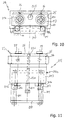
- Figs. 4 to 11 show further embodiments, wherein all reference numbers preceded by the number "2”.
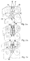
- Figs. 1a to 1c are areas of a not shown excavator boom on the one hand and a tool, e.g. a spoon, on the other hand reproduced, with the invention, generally with 11 designated device are equipped.
- Stem and bucket are with quick-change elements, in Fig.
- the moving coupling halves 18 are on one Carriage 112 possibly interchangeably attached, which is shown in the figures is not shown in detail, wherein the carriage means a piston / cylinder unit 113, 114 from a disengaged position (Fig. 2a) in a coupling position (Fig. 2b) are movable.
- the actuating cylinder 113 moves the generally designated 112 Carriage on which the protective sleeves 110 with internal Coupling halves 18 are mounted. There are Push rods 115 pushed out provided in the center holes 116 on the holder of the protective sleeves 111 to the Orientation intervene, as is the case in particular Fig. 2b shows.
- the connection A for the actuating cylinder is in Fig. 2a denoted by 117, the terminal B with 118th
- Fig. 3 is still simplified, the hydraulic control the piston-cylinder unit 113, 114 reproduced with the Pressure control valve 119 used according to the invention.
- the coupling device 21 consists of two parts, a fixed part 22 and a movable one Part 23.
- the fixed part 22 is located at one not shown in detail, hydraulically driven and can be coupled by means of a quick-change device Tool.
- the movable part 23 of the device 21 is on a quick-change device of a construction or agricultural machine arranged.
- the fixed coupling part 22 has a Case frame 24, in which a receiving block 25 by means a plurality of upper and lower side arranged spring elements 26 is spring-mounted. Inside the recording box 25, two hydraulic coupling elements 27 are arranged. They have a substantially cylindrical shape front side arranged coupling stub 28 and circumferential Grooves 29 on.
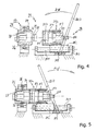
- the second half of the coupling device 21 consists of a Base frame 210 with two cylindrical slide rods 211. On the slide rods 211 is by means of two sliding bushes 212, a carriage 213a with a housing body 213 slidably stored. Inside there are two second Coupling halves 214, each with a cylindrical coupling receptacle 215 and each one cap sleeve 216 with it arranged spring-loaded retaining balls 217. Further for example, the carriage 213a has a passage 218 at the rear on, wherein in the bottom of the bottom part 210 a corresponding Blind hole 219 is provided. Through the eyelet 218 is a lever 220 Maschinenckbar, as shown in FIGS. 4 and 5 is shown.
- FIGS. 4 and 5 The function of the device shown in FIGS. 4 and 5 is the following: First, with a no closer shown tool quick-change device to be coupled Tool picked up and fixed to the boom connected to the construction machine. Following this are the two parts 22 and 23 of the coupling device 21 in the position, as shown in Fig. 4.
- the uncoupling process is as follows: The lever 220 is again through the passage receiving 218 of the carriage 213a inserted into the blind hole 219 of the base body 210 and moved in the direction of the arrow shown in Fig. 5. there Through the housing body 213, the cap sleeve 216th pulled away from the fixed coupling part 27, so that the spring-loaded retaining balls 217 from the circumferential groove 29 slip out. So get the two coupling halves 27 and 214 disengaged and the carriage 213 a can by the further movement of the lever 220 in the completely decoupled Position to be moved. This takes place simultaneously for all parallel couplings.
- the tool can be used with the quick-change device be released and replaced by another.
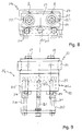
- FIG Figs. 8 and 9 An alternative embodiment of a device 21a is shown in FIG Figs. 8 and 9 are shown.
- the device 21a in turn has a fixed coupling part 22 and a displaceable coupling part 23, the arrangement of which substantially corresponds to that described above.
- a rotatably mounted threaded rod 221 which in a corresponding Thread passing hole 222 in the housing body 213 intervenes.
- the function of the device 21a corresponds the one described above, except that the effect of the displacement movement no longer by the lever 220, but is effected by the threaded rod 221.
- the housing body 213 has a continuous bore 224 through which a threaded screw 225 pushed through which is in a corresponding thread 226 in the receiving block 25 engages.
Landscapes
- Engineering & Computer Science (AREA)
- Mining & Mineral Resources (AREA)
- Civil Engineering (AREA)
- General Engineering & Computer Science (AREA)
- Structural Engineering (AREA)
- Mechanical Engineering (AREA)
- Quick-Acting Or Multi-Walled Pipe Joints (AREA)
- Agricultural Machines (AREA)
- Lifting Devices For Agricultural Implements (AREA)
Applications Claiming Priority (4)
| Application Number | Priority Date | Filing Date | Title |
|---|---|---|---|
| DE20312899U DE20312899U1 (de) | 2003-08-21 | 2003-08-21 | Vorrichtung zum Kuppeln und Entkuppeln der Anschlußenden von Druckmittelleitungen |
| DE20312899U | 2003-08-21 | ||
| DE202004004632U | 2004-03-25 | ||
| DE200420004632 DE202004004632U1 (de) | 2004-03-25 | 2004-03-25 | Vorrichtung zum Kuppeln und Entkuppeln der Anschlußenden von Druckmittelleitungen |
Publications (2)
| Publication Number | Publication Date |
|---|---|
| EP1508645A2 true EP1508645A2 (fr) | 2005-02-23 |
| EP1508645A3 EP1508645A3 (fr) | 2006-09-06 |
Family
ID=34066419
Family Applications (1)
| Application Number | Title | Priority Date | Filing Date |
|---|---|---|---|
| EP04019329A Ceased EP1508645A3 (fr) | 2003-08-21 | 2004-08-14 | Dispositif pour accoupler et découpler les bouts des conduits hydrauliques |
Country Status (1)
| Country | Link |
|---|---|
| EP (1) | EP1508645A3 (fr) |
Cited By (4)
| Publication number | Priority date | Publication date | Assignee | Title |
|---|---|---|---|---|
| FR2886320A1 (fr) * | 2005-05-27 | 2006-12-01 | Jean Paul Antiga | Dispositif pour raccorder les flexibles d'un godet orientable aux prises d'alimentation d'une pelle hydraulique |
| EP1895058A3 (fr) * | 2006-08-30 | 2008-12-17 | Faster S.p.A. | Dispositif de travail avec des moyens de couplage pour la fixation dudit dispositif à un véhicule. |
| WO2011067223A1 (fr) | 2009-12-04 | 2011-06-09 | Caterpillar Work Tools B.V. | Dispositif d'accouplement pour éléments de raccord |
| AT513587A1 (de) * | 2012-10-15 | 2014-05-15 | Perwein Baumaschinen Systeme Gmbh | Vorrichtung zur Verbindung von Leitungen |
Family Cites Families (5)
| Publication number | Priority date | Publication date | Assignee | Title |
|---|---|---|---|---|
| SE399866B (sv) * | 1975-09-12 | 1978-03-06 | Renholmens Mek Verkstad Ab | Snabbkopplingsanordning for automatisk hopkoppling av ett av en lastmaskin eller annan redskapsberare uppburet redskapsfeste med ett arbetsredskap |
| US4208163A (en) * | 1978-01-18 | 1980-06-17 | Renholmens Mekaniska Verkstad Ab | Automatic quick-coupling device |
| DE3311502C2 (de) * | 1983-03-26 | 1986-01-09 | O & K Orenstein & Koppel Ag, 1000 Berlin | Vorrichtung zum ferngesteuerten Verbinden oder Trennen zweier Koppelteile |
| DE19938876C2 (de) * | 1999-08-17 | 2002-07-11 | Voswinkel Kg | Anordnung zur Schnellkupplung von Hydrauliksystemen |
| DE20212445U1 (de) * | 2002-08-09 | 2002-11-21 | Nagler, Jürgen, 58313 Herdecke | Vorrichtung zum Kuppeln und Entkuppeln der Anschlussenden von Druckmittelleitungen |
-
2004
- 2004-08-14 EP EP04019329A patent/EP1508645A3/fr not_active Ceased
Cited By (4)
| Publication number | Priority date | Publication date | Assignee | Title |
|---|---|---|---|---|
| FR2886320A1 (fr) * | 2005-05-27 | 2006-12-01 | Jean Paul Antiga | Dispositif pour raccorder les flexibles d'un godet orientable aux prises d'alimentation d'une pelle hydraulique |
| EP1895058A3 (fr) * | 2006-08-30 | 2008-12-17 | Faster S.p.A. | Dispositif de travail avec des moyens de couplage pour la fixation dudit dispositif à un véhicule. |
| WO2011067223A1 (fr) | 2009-12-04 | 2011-06-09 | Caterpillar Work Tools B.V. | Dispositif d'accouplement pour éléments de raccord |
| AT513587A1 (de) * | 2012-10-15 | 2014-05-15 | Perwein Baumaschinen Systeme Gmbh | Vorrichtung zur Verbindung von Leitungen |
Also Published As
| Publication number | Publication date |
|---|---|
| EP1508645A3 (fr) | 2006-09-06 |
Similar Documents
| Publication | Publication Date | Title |
|---|---|---|
| EP1624116B1 (fr) | Attache rapide hydraulique | |
| DE4412115B4 (de) | Antriebsverbindung | |
| DE102011118912A1 (de) | Umwerfereinrichtung für eine Fahrradschaltung, insbesondere hintere Umwerfereinrichtung | |
| EP0034312A2 (fr) | Accouplement à action rapide accouplable aussi sous pression | |
| EP2159333B1 (fr) | Accouplement pour support d'énergie et accouplement doté d'un accouplement pour support d'énergie | |
| DE4036915A1 (de) | Werkzeugmaschine und verfahren zum oeffnen und schliessen eines greifers | |
| DE2640840C2 (fr) | ||
| EP1388616A1 (fr) | Dispositif pour accoupler et découpler les embouts de conduites d'alimentation en fluide | |
| DE3005490C2 (de) | Auch unter Druck kuppelbare Schnellverschlußkupplung | |
| DE3437505A1 (de) | Selbstzentrierendes spannfutter mit einstellbaren und austauschbaren spannbacken | |
| EP1508645A2 (fr) | Dispositif pour accoupler et découpler les bouts des conduits hydrauliques | |
| DE212011100163U1 (de) | Vorrichtung zum Bruchtrennen einer Pleuelstange | |
| DE3621951A1 (de) | Vollschlauchsystemkupplung | |
| DE102012002122B4 (de) | Verriegelungsvorrichtung für einen Teleskopausleger | |
| DE2548978B1 (de) | Rohrverbindung | |
| AT411839B (de) | Frontlader | |
| DE4412114B4 (de) | Leitungskupplungsvorrichtung | |
| DE19955289C2 (de) | Buchsenziehvorrichtung | |
| DE102004018244A1 (de) | Handschalthebel für ein Fahrzeuggetriebe | |
| DE20007050U1 (de) | Schnellwechsler für Mehrschalengreifer | |
| DE3039072C2 (de) | Auch unter Druck kuppelbare Schnellverschlußkupplung | |
| DE202004004632U1 (de) | Vorrichtung zum Kuppeln und Entkuppeln der Anschlußenden von Druckmittelleitungen | |
| DE10056649C1 (de) | Teleskopausleger mit Verriegelungselement | |
| DE4111522C2 (de) | Wechselsystem für Werkzeuge an Bediengeräten | |
| EP4204276A1 (fr) | Dispositif de verrouillage et procédé de verrouillage pour entraînement d'aiguillage et entraînement d'aiguillage |
Legal Events
| Date | Code | Title | Description |
|---|---|---|---|
| PUAI | Public reference made under article 153(3) epc to a published international application that has entered the european phase |
Free format text: ORIGINAL CODE: 0009012 |
|
| AK | Designated contracting states |
Kind code of ref document: A2 Designated state(s): AT BE BG CH CY CZ DE DK EE ES FI FR GB GR HU IE IT LI LU MC NL PL PT RO SE SI SK TR |
|
| AX | Request for extension of the european patent |
Extension state: AL HR LT LV MK |
|
| PUAL | Search report despatched |
Free format text: ORIGINAL CODE: 0009013 |
|
| AK | Designated contracting states |
Kind code of ref document: A3 Designated state(s): AT BE BG CH CY CZ DE DK EE ES FI FR GB GR HU IE IT LI LU MC NL PL PT RO SE SI SK TR |
|
| AX | Request for extension of the european patent |
Extension state: AL HR LT LV MK |
|
| 17P | Request for examination filed |
Effective date: 20070224 |
|
| AKX | Designation fees paid |
Designated state(s): AT BE BG CH CY CZ DE DK EE ES FI FR GB GR HU IE IT LI LU MC NL PL PT RO SE SI SK TR |
|
| 17Q | First examination report despatched |
Effective date: 20070420 |
|
| STAA | Information on the status of an ep patent application or granted ep patent |
Free format text: STATUS: THE APPLICATION HAS BEEN REFUSED |
|
| 18R | Application refused |
Effective date: 20090426 |