EP1508735A1 - Ventilanordnung für flüssige Medien - Google Patents
Ventilanordnung für flüssige Medien Download PDFInfo
- Publication number
- EP1508735A1 EP1508735A1 EP04018662A EP04018662A EP1508735A1 EP 1508735 A1 EP1508735 A1 EP 1508735A1 EP 04018662 A EP04018662 A EP 04018662A EP 04018662 A EP04018662 A EP 04018662A EP 1508735 A1 EP1508735 A1 EP 1508735A1
- Authority
- EP
- European Patent Office
- Prior art keywords
- valve
- servo
- valves
- control
- safety
- Prior art date
- Legal status (The legal status is an assumption and is not a legal conclusion. Google has not performed a legal analysis and makes no representation as to the accuracy of the status listed.)
- Granted
Links
- 239000012530 fluid Substances 0.000 title 1
- XLYOFNOQVPJJNP-UHFFFAOYSA-N water Substances O XLYOFNOQVPJJNP-UHFFFAOYSA-N 0.000 claims description 22
- 239000007788 liquid Substances 0.000 claims description 2
- 230000001747 exhibiting effect Effects 0.000 claims 1
- 238000010586 diagram Methods 0.000 description 2
- 230000001419 dependent effect Effects 0.000 description 1
- 238000011161 development Methods 0.000 description 1
- 230000018109 developmental process Effects 0.000 description 1
- 239000012528 membrane Substances 0.000 description 1
- 238000005096 rolling process Methods 0.000 description 1
Images



Classifications
-
- F—MECHANICAL ENGINEERING; LIGHTING; HEATING; WEAPONS; BLASTING
- F16—ENGINEERING ELEMENTS AND UNITS; GENERAL MEASURES FOR PRODUCING AND MAINTAINING EFFECTIVE FUNCTIONING OF MACHINES OR INSTALLATIONS; THERMAL INSULATION IN GENERAL
- F16K—VALVES; TAPS; COCKS; ACTUATING-FLOATS; DEVICES FOR VENTING OR AERATING
- F16K31/00—Actuating devices; Operating means; Releasing devices
- F16K31/12—Actuating devices; Operating means; Releasing devices actuated by fluid
- F16K31/36—Actuating devices; Operating means; Releasing devices actuated by fluid in which fluid from the circuit is constantly supplied to the fluid motor
- F16K31/40—Actuating devices; Operating means; Releasing devices actuated by fluid in which fluid from the circuit is constantly supplied to the fluid motor with electrically-actuated member in the discharge of the motor
- F16K31/402—Actuating devices; Operating means; Releasing devices actuated by fluid in which fluid from the circuit is constantly supplied to the fluid motor with electrically-actuated member in the discharge of the motor acting on a diaphragm
- F16K31/404—Actuating devices; Operating means; Releasing devices actuated by fluid in which fluid from the circuit is constantly supplied to the fluid motor with electrically-actuated member in the discharge of the motor acting on a diaphragm the discharge being effected through the diaphragm and being blockable by an electrically-actuated member making contact with the diaphragm
Definitions
- the invention relates to a valve arrangement for simultaneous opening and shutting off two separate supply lines for liquid media, especially for cold and hot water, with the characteristics The preamble of claim 1.
- a valve assembly is known and described for example in EP 0 401 468 A2.
- the known valve arrangement has the electromagnetic Control device for controlling the two servo valves a Magnetic coil, in whose coil axis a guide tube is arranged, in which two armature on both sides of the transverse center plane the solenoid are slidably disposed, wherein to each other opposite ends of the armature each have a magnet armature seal is arranged by means of a the control room with The discharge passage connecting the respective valve outlet can be closed is.
- the common electromagnetic control device arranged in the space between the two supply lines. Because of two different, from the same solenoid actuated, coaxially arranged magnet armature available are, results in a relatively large amount of space in the space between the two supply lines, especially in the sanitary area is not always is available.
- the invention has for its object to provide a valve assembly to design the features of the preamble of claim 1 in such a way on the one hand the valve arrangement with very little Space requirements between the two leads are arranged can and on the other hand cost and energy needs and the possibility of errors the arrangement can be reduced. Furthermore, a should Safety device be provided by which prevented is that when using the valve assembly, for example in a shower application, in case of failure of the cold water supply too dangerous scalding can happen if only hot Water is spent.
- the common electromagnetic control device as only one form common magnet armature having pilot valve, by the one common in the two control spaces of the servo-valves Relief channel is closable and in or in front of the common Discharge channel in series with the pilot valve, to arrange hydraulically controllable safety valve, the is controlled by the inlet pressure in one of the two supply lines and the discharge channel only opens when in the relevant supply line a predetermined minimum pressure prevails.
- the Valve arrangement according to the invention in a shower application is the Supply line from which the safety valve is driven, preferably the cold water leading supply line.
- the inventive Forming the valve assembly has the consequence that an opening of the two servo valves from the pilot valve is only possible if in the Cold water leading supply line of the specified minimum pressure prevails, and thereby prevents, for example, only hot water is delivered.
- the valve arrangement according to the invention can be very compact build by the safety valve in a substantially between the two supply lines lying valve block is arranged, the inflow and outflow channels and the control channel to the safety valve contains. To the valve block can then laterally be connected to the pilot valve, the supply and discharge lines the pilot valve are also passed through the valve block. At the two ends of this valve block, the valve body the servo valves are attached, with the control spaces of the servo valves can be incorporated in the valve block and the common Relief channel is also arranged in the valve block.
- Fig. 1 is a valve arrangement for simultaneous opening and Shut off two separate supply lines for cold and hot Water shown in the form of a hydraulic circuit diagram.
- a check valve R1 connected to a first servo-valve 1 of known type with a valve inlet E1 and a valve outlet A1.
- a second servo-valve. 2 connected with a valve inlet E2 and a valve outlet A2.
- the exact structure of these two servo valves will continue explained below.
- For controlling the two servo valves 1 and 2 serves a pilot valve 3 with a via an inlet channel 5.1 to the both control rooms of the servo valves 1 and 2 connected Valve input E3 and one connected to a drain channel 5.2 Valve outlet A3.
- the pilot valve 3 is a solenoid valve educated.
- the outlet channel 5.2 of the pilot valve 3 is simultaneously Inlet channel for a safety valve 4 with a valve inlet E4 and a valve outlet A4, via a flow channel 5.31 on the common discharge channel 5.3 is connected with the the two valve outputs A1 and A2 of the servo valves 1 and 2 connected is.
- the safety valve is with its control input S4 to the cold water leading supply line K in front of the valve inlet E1 connected to the relevant servo-valve 1.
- the pilot valve 3 In the closed state of the pilot valve 3 prevails, as in itself known and explained below, in the control rooms of the two Servo valves 1 and 2 on the two servo valves in the closed Condition holding back pressure.
- the pilot valve To open both servo valves 1 and 2, the pilot valve is activated in the manner the flow is released from the inlet channel 5.1 to the outlet channel 5.2 becomes. If then the safety valve 4 in the open position are located, the two control chambers of the servo valves 1 and 2 connected to the common discharge channel 5.3, so that the pressure relief of the two control rooms for Opening the two servo valves 1 and 2 leads.
- the safety valve 4 is a so-called NC valve constructed, which is closed in the absence of control pressure.
- valve arrangement shown in FIG. 1 it is ensured that in case of failure of the cold water supply no hot water delivered can be.
- the two servo valves 1 and 2 are in principle constructed as also described in EP 0 401 468 A2.
- Fig. 2 supply lines flows cold Water to input E1 of servo valve 1 and warm water to the input E2 of the servo valve 2.
- the servo valves may be a mixing device, not shown connect.
- the terminals E1 and A1 or E2 and A2 are shown in the Embodiment arranged at a relatively small distance from each other, so that a valve block 5 can be arranged between them can, in or on which the safety valve 4 and the pilot valve 3rd are arranged.
- the servo valves have valve housings 1.1 and 2.1, each to the opposite ends of the Valve block 5 are attached.
- a differential piston 1.21 or 2.21 is movably arranged.
- the differential pistons each carry the into a rolling membrane integrated valve disk 1.2 or 2.2, which a valve seat 1.3 or 2.3 are opposite.
- the valve inputs E1 and E2 are respectively connected to a pressure chamber 1.4 or 2.4, over the Valve seat 1.3 or 2.3 connected to the valve outlet A1 or A2 is.
- the pressure chambers 1.4 and 2.4 are on one side of the Valve disc 1.2 or 2.2, while on the other side of the valve plate or the differential piston 1.21 and 2.21 each have a control chamber 1.5 or 2.5 is arranged.
- These control rooms are how out Fig. 2 can be seen, incorporated in the end surfaces of the valve block 5.
- Each of the control rooms 1.5 and 2.5 is at the already mentioned Supply channel 5.1 connected to the pilot valve 3 and thus on the Outflow channel 5.2 of the pilot valve and the safety valve 4 to the Relief channel 5.3.
- the channels 5.1, 5.2 and 5.3 are in the valve block 5 arranged.
- the control spaces are 1.5 and 2.5 via a respectively arranged in the differential piston control bore 1.51 or 2.51 connected to the pressure chamber 1.4 or 2.4.
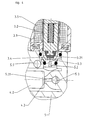
- the pilot valve 3 is attached laterally to the valve block 5. It has a housing 3.1, in which a magnetic coil is 3.5, in which a magnet armature is guided 3.2, at its inner End carries a magnet anchor seal 3.21, which is inside the Pilot valve chamber 3.4 a pilot valve seat 3.3 is opposite.
- a pilot valve chamber 3.4 opens the inlet channel 5.1 for the pilot valve (see Fig. 4), which via the adjoining the pilot valve seat Outflow channel 5.2 to which also disposed within the valve block 5
- Valve chamber 4.4 of the safety valve 4 is connected.
- the safety valve 4 integrated in the valve block is designed as a diaphragm valve built up.
- valve seat 4.3 in the Valve chamber 4.4 opposite closure member 4.2 the in a control diaphragm 4.6 is integrated, the one against the valve chamber 4.4 sealed control room 4.5 limited.
- the valve chamber 4.4 of the safety valve is on the valve seat 4.3 to the common discharge channel 5.3 connected (Fig. 4).
- Of the Control chamber 4.5 of the safety valve 4 is via a control channel 5.4 to the control chamber 1.5 of the servo-valve 1 and thus to the Input E1 of the cold water leading servo-valve 1 connected.
- the control diaphragm 4.6 is under the force of a Spring 4.7.
- the access to the parts of the safety valve 4 is by a screwed onto the valve block 5 valve cap 4.1 covered.
- the pilot valve 3 is connected via an electrical supply line 3.51 supplied to the necessary electrical voltage.
- the Funktonsweise the valve assembly of Fig. 2 to 6 has already been explained above with reference to FIG. 1.
Landscapes
- Engineering & Computer Science (AREA)
- General Engineering & Computer Science (AREA)
- Mechanical Engineering (AREA)
- Fluid-Driven Valves (AREA)
- Multiple-Way Valves (AREA)
- Feeding And Controlling Fuel (AREA)
- Temperature-Responsive Valves (AREA)
- Lift Valve (AREA)
- Magnetically Actuated Valves (AREA)
- Servomotors (AREA)
Abstract
Description
Claims (6)
- Ventilanordnung zum gleichzeitigen Öffnen und Absperren zweier getrennter Zuleitungen für flüssige Medien, insbesondere für kaltes und heißes Wasser, wobei in jeder der Zuleitungen ein eigenmediumbetätigtes, durch ein elektromagnetisches Pilotventil gesteuertes Servo-Ventil angeordnet ist mit einem in einem Ventilgehäuse bewegbar angeordneten, den Ventilteller tragenden Differentialkolben, an dessen einer Seite ein mit dem Ventileingang verbundener Druckraum angeordnet ist, der über einen dem Ventilteller gegenüberliegenden Ventilsitz mit dem Ventilausgang verbunden ist, und an dessen anderer Seite ein Steuerraum angeordnet ist, der über einen mittels eines Pilotventils verschließbaren Entlastungskanal mit dem Ventilausgang und über eine im Differentialkolben angeordnete Steuerbohrung mit dem Druckraum verbunden ist, wobei beide Servo-Ventile von einer gemeinsamen elektromagnetischen Steuervorrichtung her angesteuert werden, dadurch gekennzeichnet, dass die gemeinsame elektromagnetische Steuervorrichtung als ein beide Servo-Ventile (1, 2) gleichzeitig ansteuerndes, einen gemeinsamen Magnetanker (3.2) aufweisendes Pilotventil (3) ausgebildet ist, dessen Ventileingang (E3) mit den Steuerräumen (1.5, 2.5) beider Servo-Ventile (1, 2) verbunden ist und dessen Ventilausgang (A3) über einen beiden Servo-Ventilen (1, 2) gemeinsamen Entlastungskanal (5.3) mit den Ausgängen (A1, A2) der Servo-Ventile (1, 2) verbunden ist, wobei in oder vor den gemeinsamen Entlastungskanal (5.3) ein hydraulisch ansteuerbares Sicherheitsventil (4) eingeschaltet ist, dessen Steuereingang (S4) an eine der Zuleitungen (K) angeschlossen ist derart, dass der Entlastungskanal (5.3) nur geöffnet wird, wenn in der betreffenden Zuleitung (K) ein vorgegebener Mindestdruck herrscht.
- Ventilanordnung nach Anspruch 1, dadurch gekennzeichnet, dass der Steuereingang(S4) des Sicherheitsventils (4) an die Kaltwasser führende Zuleitung (K).angeschlossen ist.
- Ventilanordnung nach Anspruch 1 oder 2, dadurch gekennzeichnet, dass das Sicherheitsventil (4) als Membranventil aufgebaut ist mit mindestens einer, eine Steuerkammer (4.5) begrenzende, unter Federkraft stehende Membran (4.6), an der in einer Sicherheits-Ventilkammer (4.4) ein Verschlussorgan (4.2) befestigt ist, das einem Sicherheits-Ventilsitz (4.3) gegenüberliegt, über den die an den Ventilausgang (A3) des Pilotventils (3) angeschlossene Sicherheits-Ventilkammer (4.4) mit dem zu den Ausgängen der Servo-Ventile (1, 2) führenden Entlastungskanal (5.3) verbindbar ist, wobei die Steuerkammer (4.5) über einen Steuerkanal (5.4) mit dem Ventileingang (E1) eines der Servo-Ventile (1) verbunden ist.
- Ventilanordnung nach Anspruch 3, dadurch gekennzeichnet, dass das Sicherheitsventil (4) in einem im wesentlichen zwischen den beiden Zuleitungen (K, W) liegenden Ventilblock (5) angeordnet ist, der die Zu- und Abflusskanäle (5.2, 5.3) sowie den Steuerkanal (5.4) zum Sicherheitsventil (4) enthält.
- Ventilanordnung nach Anspruch 4, dadurch gekennzeichnet, dass an die beiden Enden des Ventilblocks (5) die Ventilgehäuse (1.1, 2.1) der Servo-Ventile (1, 2) angesetzt sind, wobei die Steuerräume (1.5, 2.5) der Servo-Ventile (1, 2) in den Ventilblock (5) eingearbeitet sind und der Entlastungskanal (5.3) im Ventilblock (5) angeordnet ist.
- Ventilanordnung nach Anspruch 5, dadurch gekennzeichnet, dass an den Ventilblock (5) seitlich das Pilotventil (3) angesetzt ist und die Zu- und Abführungskanäle (5.1, 5.2) des Pilotventils (3) durch den Ventilblock (5) geführt sind.
Applications Claiming Priority (2)
| Application Number | Priority Date | Filing Date | Title |
|---|---|---|---|
| DE10338332 | 2003-08-21 | ||
| DE10338332A DE10338332A1 (de) | 2003-08-21 | 2003-08-21 | Ventilanordnung zum gleichzeitigen Öffnen und Absperren zweier getrennter Zuleitungen für flüssige Medien, insbesondere für kaltes und heisses Wasser |
Publications (2)
| Publication Number | Publication Date |
|---|---|
| EP1508735A1 true EP1508735A1 (de) | 2005-02-23 |
| EP1508735B1 EP1508735B1 (de) | 2006-01-25 |
Family
ID=34042217
Family Applications (1)
| Application Number | Title | Priority Date | Filing Date |
|---|---|---|---|
| EP04018662A Expired - Lifetime EP1508735B1 (de) | 2003-08-21 | 2004-08-06 | Ventilanordnung für flüssige Medien |
Country Status (3)
| Country | Link |
|---|---|
| EP (1) | EP1508735B1 (de) |
| AT (1) | ATE316633T1 (de) |
| DE (2) | DE10338332A1 (de) |
Cited By (1)
| Publication number | Priority date | Publication date | Assignee | Title |
|---|---|---|---|---|
| US11306844B2 (en) | 2017-06-26 | 2022-04-19 | Lixil Corporation | Pilot solenoid valve |
Citations (3)
| Publication number | Priority date | Publication date | Assignee | Title |
|---|---|---|---|---|
| GB751031A (en) * | 1953-03-17 | 1956-06-27 | Ross Operating Valve Co | Improvements in or relating to a system for controlling a fluid actuated device |
| EP0401468A2 (de) * | 1989-03-08 | 1990-12-12 | A. und K. Müller GmbH & Co. KG | Ventilanordnung zum gleichzeitigen Öffnen und Absperren zweier getrennter Zuleitungen für flüssige oder gasförmige Medien |
| US6508272B1 (en) * | 2000-11-20 | 2003-01-21 | Arichell Technologies, Inc. | Device and method for operating at least two valves |
-
2003
- 2003-08-21 DE DE10338332A patent/DE10338332A1/de not_active Withdrawn
-
2004
- 2004-08-06 EP EP04018662A patent/EP1508735B1/de not_active Expired - Lifetime
- 2004-08-06 AT AT04018662T patent/ATE316633T1/de not_active IP Right Cessation
- 2004-08-06 DE DE502004000261T patent/DE502004000261D1/de not_active Expired - Lifetime
Patent Citations (3)
| Publication number | Priority date | Publication date | Assignee | Title |
|---|---|---|---|---|
| GB751031A (en) * | 1953-03-17 | 1956-06-27 | Ross Operating Valve Co | Improvements in or relating to a system for controlling a fluid actuated device |
| EP0401468A2 (de) * | 1989-03-08 | 1990-12-12 | A. und K. Müller GmbH & Co. KG | Ventilanordnung zum gleichzeitigen Öffnen und Absperren zweier getrennter Zuleitungen für flüssige oder gasförmige Medien |
| US6508272B1 (en) * | 2000-11-20 | 2003-01-21 | Arichell Technologies, Inc. | Device and method for operating at least two valves |
Cited By (1)
| Publication number | Priority date | Publication date | Assignee | Title |
|---|---|---|---|---|
| US11306844B2 (en) | 2017-06-26 | 2022-04-19 | Lixil Corporation | Pilot solenoid valve |
Also Published As
| Publication number | Publication date |
|---|---|
| EP1508735B1 (de) | 2006-01-25 |
| DE10338332A1 (de) | 2005-03-17 |
| ATE316633T1 (de) | 2006-02-15 |
| DE502004000261D1 (de) | 2006-04-13 |
Similar Documents
| Publication | Publication Date | Title |
|---|---|---|
| DE19826076C1 (de) | Doppelsicherheitsventil | |
| EP0872674B1 (de) | Druckausgeglichenes Magnetventil | |
| DE2450094C3 (de) | ||
| DE2543466C3 (de) | Fluidgesteuertes Ventil | |
| DE3523917A1 (de) | Von einem steuerorgan betaetigtes steuerungsventil | |
| DE3819536A1 (de) | Tuerschliesser | |
| DE69708991T3 (de) | Wechselventil mit Mitteln zur Vermeidung von Gegenstrom | |
| DE3842633A1 (de) | Vorgesteuertes mehrwegeventil | |
| DE1425686A1 (de) | Stroemungsmittelbetaetigte Ventile | |
| EP1255066A2 (de) | Koaxialventil | |
| EP1781953B1 (de) | Pilotventil, insbesondere für servoventile | |
| DE3134065C2 (de) | ||
| DE102007010213B3 (de) | Elektromagnetisches Regelventil und Verfahren zu dessen Steuerung | |
| EP0401468B1 (de) | Ventilanordnung zum gleichzeitigen Öffnen und Absperren zweier getrennter Zuleitungen für flüssige oder gasförmige Medien | |
| EP0041247B1 (de) | Vorgesteuerte Vorrichtung zur lastunabhängigen Volumenstromregelung | |
| EP1508735B1 (de) | Ventilanordnung für flüssige Medien | |
| EP3070383B1 (de) | Servoventil | |
| DE19932139B4 (de) | Vorgesteuertes Schieberventil | |
| DE3525331A1 (de) | Hydraulisch betaetigtes selbstschliessendes zwei-wege-sitzventil | |
| EP1429064A1 (de) | Servo-Magnetventil | |
| DE1650504A1 (de) | Ventileinheit | |
| DE7834499U1 (de) | Servobetaetigtes dreiwegeventil | |
| EP0056423A1 (de) | Elektromagnet-betätigtes Mehrstellungs/Mehrwege-Hydraulikventil | |
| EP3686465A1 (de) | Schnellschaltventil | |
| EP1510699B1 (de) | Verfahren und Vorrichtung zur Flutumschaltung |
Legal Events
| Date | Code | Title | Description |
|---|---|---|---|
| PUAI | Public reference made under article 153(3) epc to a published international application that has entered the european phase |
Free format text: ORIGINAL CODE: 0009012 |
|
| AK | Designated contracting states |
Kind code of ref document: A1 Designated state(s): AT BE BG CH CY CZ DE DK EE ES FI FR GB GR HU IE IT LI LU MC NL PL PT RO SE SI SK TR |
|
| AX | Request for extension of the european patent |
Extension state: AL HR LT LV MK |
|
| 17P | Request for examination filed |
Effective date: 20050607 |
|
| GRAP | Despatch of communication of intention to grant a patent |
Free format text: ORIGINAL CODE: EPIDOSNIGR1 |
|
| RIN1 | Information on inventor provided before grant (corrected) |
Inventor name: BERGER, GERD Inventor name: NUSSBAUM, DANIEL Inventor name: RIEDEL HEINZ-DIETER Inventor name: GLAUS, UWE |
|
| AKX | Designation fees paid |
Designated state(s): AT BE BG CH CY CZ DE DK EE ES FI FR GB GR HU IE IT LI LU MC NL PL PT RO SE SI SK TR |
|
| GRAS | Grant fee paid |
Free format text: ORIGINAL CODE: EPIDOSNIGR3 |
|
| GRAA | (expected) grant |
Free format text: ORIGINAL CODE: 0009210 |
|
| AK | Designated contracting states |
Kind code of ref document: B1 Designated state(s): AT BE BG CH CY CZ DE DK EE ES FI FR GB GR HU IE IT LI LU MC NL PL PT RO SE SI SK TR |
|
| PG25 | Lapsed in a contracting state [announced via postgrant information from national office to epo] |
Ref country code: SI Free format text: LAPSE BECAUSE OF FAILURE TO SUBMIT A TRANSLATION OF THE DESCRIPTION OR TO PAY THE FEE WITHIN THE PRESCRIBED TIME-LIMIT Effective date: 20060125 Ref country code: SK Free format text: LAPSE BECAUSE OF FAILURE TO SUBMIT A TRANSLATION OF THE DESCRIPTION OR TO PAY THE FEE WITHIN THE PRESCRIBED TIME-LIMIT Effective date: 20060125 Ref country code: FI Free format text: LAPSE BECAUSE OF FAILURE TO SUBMIT A TRANSLATION OF THE DESCRIPTION OR TO PAY THE FEE WITHIN THE PRESCRIBED TIME-LIMIT Effective date: 20060125 Ref country code: IE Free format text: LAPSE BECAUSE OF FAILURE TO SUBMIT A TRANSLATION OF THE DESCRIPTION OR TO PAY THE FEE WITHIN THE PRESCRIBED TIME-LIMIT Effective date: 20060125 Ref country code: NL Free format text: LAPSE BECAUSE OF FAILURE TO SUBMIT A TRANSLATION OF THE DESCRIPTION OR TO PAY THE FEE WITHIN THE PRESCRIBED TIME-LIMIT Effective date: 20060125 Ref country code: RO Free format text: LAPSE BECAUSE OF FAILURE TO SUBMIT A TRANSLATION OF THE DESCRIPTION OR TO PAY THE FEE WITHIN THE PRESCRIBED TIME-LIMIT Effective date: 20060125 Ref country code: PL Free format text: LAPSE BECAUSE OF FAILURE TO SUBMIT A TRANSLATION OF THE DESCRIPTION OR TO PAY THE FEE WITHIN THE PRESCRIBED TIME-LIMIT Effective date: 20060125 |
|
| REG | Reference to a national code |
Ref country code: GB Ref legal event code: FG4D Free format text: NOT ENGLISH |
|
| REG | Reference to a national code |
Ref country code: CH Ref legal event code: EP |
|
| REG | Reference to a national code |
Ref country code: IE Ref legal event code: FG4D Free format text: LANGUAGE OF EP DOCUMENT: GERMAN |
|
| REG | Reference to a national code |
Ref country code: CH Ref legal event code: NV Representative=s name: A. BRAUN, BRAUN, HERITIER, ESCHMANN AG PATENTANWAE |
|
| GBT | Gb: translation of ep patent filed (gb section 77(6)(a)/1977) |
Effective date: 20060320 |
|
| REF | Corresponds to: |
Ref document number: 502004000261 Country of ref document: DE Date of ref document: 20060413 Kind code of ref document: P |
|
| PG25 | Lapsed in a contracting state [announced via postgrant information from national office to epo] |
Ref country code: DK Free format text: LAPSE BECAUSE OF FAILURE TO SUBMIT A TRANSLATION OF THE DESCRIPTION OR TO PAY THE FEE WITHIN THE PRESCRIBED TIME-LIMIT Effective date: 20060425 Ref country code: SE Free format text: LAPSE BECAUSE OF FAILURE TO SUBMIT A TRANSLATION OF THE DESCRIPTION OR TO PAY THE FEE WITHIN THE PRESCRIBED TIME-LIMIT Effective date: 20060425 Ref country code: BG Free format text: LAPSE BECAUSE OF FAILURE TO SUBMIT A TRANSLATION OF THE DESCRIPTION OR TO PAY THE FEE WITHIN THE PRESCRIBED TIME-LIMIT Effective date: 20060425 |
|
| PG25 | Lapsed in a contracting state [announced via postgrant information from national office to epo] |
Ref country code: ES Free format text: LAPSE BECAUSE OF FAILURE TO SUBMIT A TRANSLATION OF THE DESCRIPTION OR TO PAY THE FEE WITHIN THE PRESCRIBED TIME-LIMIT Effective date: 20060506 |
|
| PG25 | Lapsed in a contracting state [announced via postgrant information from national office to epo] |
Ref country code: PT Free format text: LAPSE BECAUSE OF FAILURE TO SUBMIT A TRANSLATION OF THE DESCRIPTION OR TO PAY THE FEE WITHIN THE PRESCRIBED TIME-LIMIT Effective date: 20060626 |
|
| NLV1 | Nl: lapsed or annulled due to failure to fulfill the requirements of art. 29p and 29m of the patents act | ||
| ET | Fr: translation filed | ||
| REG | Reference to a national code |
Ref country code: IE Ref legal event code: FD4D |
|
| PG25 | Lapsed in a contracting state [announced via postgrant information from national office to epo] |
Ref country code: MC Free format text: LAPSE BECAUSE OF NON-PAYMENT OF DUE FEES Effective date: 20060831 Ref country code: BE Free format text: LAPSE BECAUSE OF NON-PAYMENT OF DUE FEES Effective date: 20060831 |
|
| PLBE | No opposition filed within time limit |
Free format text: ORIGINAL CODE: 0009261 |
|
| STAA | Information on the status of an ep patent application or granted ep patent |
Free format text: STATUS: NO OPPOSITION FILED WITHIN TIME LIMIT |
|
| 26N | No opposition filed |
Effective date: 20061026 |
|
| PG25 | Lapsed in a contracting state [announced via postgrant information from national office to epo] |
Ref country code: AT Free format text: LAPSE BECAUSE OF NON-PAYMENT OF DUE FEES Effective date: 20060806 |
|
| BERE | Be: lapsed |
Owner name: A. UND K. MULLER G.M.B.H. & CO. KG Effective date: 20060831 |
|
| PG25 | Lapsed in a contracting state [announced via postgrant information from national office to epo] |
Ref country code: CZ Free format text: LAPSE BECAUSE OF FAILURE TO SUBMIT A TRANSLATION OF THE DESCRIPTION OR TO PAY THE FEE WITHIN THE PRESCRIBED TIME-LIMIT Effective date: 20060125 Ref country code: GR Free format text: LAPSE BECAUSE OF FAILURE TO SUBMIT A TRANSLATION OF THE DESCRIPTION OR TO PAY THE FEE WITHIN THE PRESCRIBED TIME-LIMIT Effective date: 20060426 |
|
| REG | Reference to a national code |
Ref country code: CH Ref legal event code: PFA Owner name: A. UND K. MUELLER GMBH & CO. KG Free format text: A. UND K. MUELLER GMBH & CO. KG#DRESDENER STRASSE 162#40595 DUESSELDORF (DE) -TRANSFER TO- A. UND K. MUELLER GMBH & CO. KG#DRESDENER STRASSE 162#40595 DUESSELDORF (DE) |
|
| PG25 | Lapsed in a contracting state [announced via postgrant information from national office to epo] |
Ref country code: EE Free format text: LAPSE BECAUSE OF FAILURE TO SUBMIT A TRANSLATION OF THE DESCRIPTION OR TO PAY THE FEE WITHIN THE PRESCRIBED TIME-LIMIT Effective date: 20060125 |
|
| PG25 | Lapsed in a contracting state [announced via postgrant information from national office to epo] |
Ref country code: TR Free format text: LAPSE BECAUSE OF FAILURE TO SUBMIT A TRANSLATION OF THE DESCRIPTION OR TO PAY THE FEE WITHIN THE PRESCRIBED TIME-LIMIT Effective date: 20060125 Ref country code: LU Free format text: LAPSE BECAUSE OF NON-PAYMENT OF DUE FEES Effective date: 20060806 Ref country code: HU Free format text: LAPSE BECAUSE OF FAILURE TO SUBMIT A TRANSLATION OF THE DESCRIPTION OR TO PAY THE FEE WITHIN THE PRESCRIBED TIME-LIMIT Effective date: 20060726 |
|
| PG25 | Lapsed in a contracting state [announced via postgrant information from national office to epo] |
Ref country code: CY Free format text: LAPSE BECAUSE OF FAILURE TO SUBMIT A TRANSLATION OF THE DESCRIPTION OR TO PAY THE FEE WITHIN THE PRESCRIBED TIME-LIMIT Effective date: 20060125 |
|
| PGFP | Annual fee paid to national office [announced via postgrant information from national office to epo] |
Ref country code: GB Payment date: 20080730 Year of fee payment: 5 |
|
| GBPC | Gb: european patent ceased through non-payment of renewal fee |
Effective date: 20090806 |
|
| PG25 | Lapsed in a contracting state [announced via postgrant information from national office to epo] |
Ref country code: GB Free format text: LAPSE BECAUSE OF NON-PAYMENT OF DUE FEES Effective date: 20090806 |
|
| PGFP | Annual fee paid to national office [announced via postgrant information from national office to epo] |
Ref country code: FR Payment date: 20100812 Year of fee payment: 7 |
|
| PGFP | Annual fee paid to national office [announced via postgrant information from national office to epo] |
Ref country code: CH Payment date: 20110823 Year of fee payment: 8 |
|
| PGFP | Annual fee paid to national office [announced via postgrant information from national office to epo] |
Ref country code: IT Payment date: 20110823 Year of fee payment: 8 |
|
| REG | Reference to a national code |
Ref country code: FR Ref legal event code: ST Effective date: 20120430 |
|
| PG25 | Lapsed in a contracting state [announced via postgrant information from national office to epo] |
Ref country code: FR Free format text: LAPSE BECAUSE OF NON-PAYMENT OF DUE FEES Effective date: 20110831 |
|
| REG | Reference to a national code |
Ref country code: CH Ref legal event code: PL |
|
| PG25 | Lapsed in a contracting state [announced via postgrant information from national office to epo] |
Ref country code: LI Free format text: LAPSE BECAUSE OF NON-PAYMENT OF DUE FEES Effective date: 20120831 Ref country code: CH Free format text: LAPSE BECAUSE OF NON-PAYMENT OF DUE FEES Effective date: 20120831 |
|
| PG25 | Lapsed in a contracting state [announced via postgrant information from national office to epo] |
Ref country code: IT Free format text: LAPSE BECAUSE OF NON-PAYMENT OF DUE FEES Effective date: 20120806 |
|
| PGFP | Annual fee paid to national office [announced via postgrant information from national office to epo] |
Ref country code: DE Payment date: 20160831 Year of fee payment: 13 |
|
| REG | Reference to a national code |
Ref country code: DE Ref legal event code: R119 Ref document number: 502004000261 Country of ref document: DE |
|
| PG25 | Lapsed in a contracting state [announced via postgrant information from national office to epo] |
Ref country code: DE Free format text: LAPSE BECAUSE OF NON-PAYMENT OF DUE FEES Effective date: 20180301 |