EP1508873A1 - Connecteur de carte mémoire - Google Patents
Connecteur de carte mémoire Download PDFInfo
- Publication number
- EP1508873A1 EP1508873A1 EP04019691A EP04019691A EP1508873A1 EP 1508873 A1 EP1508873 A1 EP 1508873A1 EP 04019691 A EP04019691 A EP 04019691A EP 04019691 A EP04019691 A EP 04019691A EP 1508873 A1 EP1508873 A1 EP 1508873A1
- Authority
- EP
- European Patent Office
- Prior art keywords
- memory card
- card
- connector
- swing slider
- housing
- Prior art date
- Legal status (The legal status is an assumption and is not a legal conclusion. Google has not performed a legal analysis and makes no representation as to the accuracy of the status listed.)
- Granted
Links
Images


Classifications
-
- H—ELECTRICITY
- H01—ELECTRIC ELEMENTS
- H01R—ELECTRICALLY-CONDUCTIVE CONNECTIONS; STRUCTURAL ASSOCIATIONS OF A PLURALITY OF MUTUALLY-INSULATED ELECTRICAL CONNECTING ELEMENTS; COUPLING DEVICES; CURRENT COLLECTORS
- H01R12/00—Structural associations of a plurality of mutually-insulated electrical connecting elements, specially adapted for printed circuits, e.g. printed circuit boards [PCB], flat or ribbon cables, or like generally planar structures, e.g. terminal strips, terminal blocks; Coupling devices specially adapted for printed circuits, flat or ribbon cables, or like generally planar structures; Terminals specially adapted for contact with, or insertion into, printed circuits, flat or ribbon cables, or like generally planar structures
- H01R12/70—Coupling devices
- H01R12/71—Coupling devices for rigid printing circuits or like structures
-
- G—PHYSICS
- G06—COMPUTING OR CALCULATING; COUNTING
- G06K—GRAPHICAL DATA READING; PRESENTATION OF DATA; RECORD CARRIERS; HANDLING RECORD CARRIERS
- G06K13/00—Conveying record carriers from one station to another, e.g. from stack to punching mechanism
- G06K13/02—Conveying record carriers from one station to another, e.g. from stack to punching mechanism the record carrier having longitudinal dimension comparable with transverse dimension, e.g. punched card
- G06K13/08—Feeding or discharging cards
- G06K13/0806—Feeding or discharging cards using an arrangement for ejection of an inserted card
- G06K13/0825—Feeding or discharging cards using an arrangement for ejection of an inserted card the ejection arrangement being of the push-push kind
-
- G—PHYSICS
- G06—COMPUTING OR CALCULATING; COUNTING
- G06K—GRAPHICAL DATA READING; PRESENTATION OF DATA; RECORD CARRIERS; HANDLING RECORD CARRIERS
- G06K13/00—Conveying record carriers from one station to another, e.g. from stack to punching mechanism
- G06K13/02—Conveying record carriers from one station to another, e.g. from stack to punching mechanism the record carrier having longitudinal dimension comparable with transverse dimension, e.g. punched card
- G06K13/08—Feeding or discharging cards
- G06K13/085—Feeding or discharging cards using an arrangement for locking the inserted card
-
- G—PHYSICS
- G06—COMPUTING OR CALCULATING; COUNTING
- G06K—GRAPHICAL DATA READING; PRESENTATION OF DATA; RECORD CARRIERS; HANDLING RECORD CARRIERS
- G06K17/00—Methods or arrangements for effecting co-operative working between equipments covered by two or more of main groups G06K1/00 - G06K15/00, e.g. automatic card files incorporating conveying and reading operations
-
- H—ELECTRICITY
- H01—ELECTRIC ELEMENTS
- H01R—ELECTRICALLY-CONDUCTIVE CONNECTIONS; STRUCTURAL ASSOCIATIONS OF A PLURALITY OF MUTUALLY-INSULATED ELECTRICAL CONNECTING ELEMENTS; COUPLING DEVICES; CURRENT COLLECTORS
- H01R13/00—Details of coupling devices of the kinds covered by groups H01R12/70 or H01R24/00 - H01R33/00
- H01R13/62—Means for facilitating engagement or disengagement of coupling parts or for holding them in engagement
- H01R13/627—Snap or like fastening
- H01R13/6275—Latching arms not integral with the housing
Definitions
- the present invention relates to a memory card connector for establishing an electrical connection with a memory card exemplified by a miniSD (Secure Digital) card based on the SDA (Standard Card Association) standard through insertion thereof and, more specifically, to a memory card connector with a lock mechanism for retaining a memory card at its inserted position.
- miniSD Secure Digital
- SDA Standard Card Association
- a memory card serving as a card storage unit includes flash memory for a storage medium.
- the memory card is very small in size, and thus consumes very little electricity for data reading and writing. With such advantages, the memory card has been popular especially as recording medium typically for camera-equipped mobile phones and PDAs (Personal Digital Assistances).
- the memory cards are smaller in storage capacity and higher in price.
- the storage capacity of the memory cards is increased up to about 128 MB, and the price thereof is reduced.
- the memory cards require no drive for data reading and writing.
- the memory cards are considered preferable as storage media for digital cameras, notebook PCs, and portable music players those placing prime importance on power-thriftiness and portability.
- the miniSD card has the outer dimensions of 21.55 mm (length) ⁇ 20 mm (width) ⁇ 1.4 mm (thickness).
- the SD card has the outer dimensions of 32.2 mm (length) ⁇ 24 mm (width) ⁇ 2.1 mm (thickness).
- the miniSD card is reduced in capacity about 60%.
- Another difference of the miniSD card from the SD card is the number of connector terminals provided on the surface, i.e., 11 pins for the miniSD card and 9 pins for the SD card.
- a memory card connector For data reading and writing from/to such a memory card, a memory card connector has appeared in the market to serve as a connector for the purpose.
- the memory card connector is provided with a lock mechanism to prevent a memory card inserted into a housing from being detached or pulled out.
- a lock mechanism to prevent a memory card inserted into a housing from being detached or pulled out.
- the above memory card connector includes the housing, a shield plate which is attached as to cover the housing upper surface and both side surfaces, the lock mechanism for locking the inserted memory card, and a connector pin retention section formed in one piece with the housing.
- the lock mechanism includes a lock member which is provided for engaging with the memory card inserted into a memory card insertion section to lock the memory card at its predetermined insertion position, a slider for supporting the lock member, an ejection coil spring for biasing the slider in the pull-out direction, and a lock pin which is provided for engaging with a heart cam formed to the slider to latch the slider at its attachment position.
- an object of the present invention is to provide a memory card connector capable of preventing a memory card from popping out therefrom.
- a first aspect of the present invention is directed to A connector comprising, a housing, a cover for covering the housing, and wherein the housing includes, a card retention section of substantially a box shape having a card insertion port for accepting therein a memory card, a plurality of contacts which faces the card insertion port to electrically contact with a distal end side of the memory card, a swing slider which is provided to freely swing in a direction substantially orthogonal to an insertion direction of the memory card, and engages with the distal end and a concave section on a side of the memory card to slide with the memory card in an insertion direction when once the memory card is inserted into the card insertion port of the card retention section, and a lock mechanism for swinging the swing slider toward inside to retain the memory card when the memory card reaches a proximal end side of the housing.
- the connector according to the first aspect of the present invention, wherein the swing slider has a cam channel of a heart shape, wherein the lock mechanism includes a biasing member for biasing the swing slider toward inside of the card retention section and a guide rod engaged with the cam channel of the swing slider, and whereby the guide rod moves along the cam channel, and the swing slider is pulled by the biasing member and moves toward the card insertion port while engaging with the concave section and the distal end of the memory card when the memory card in a retained state is pushed in the insertion direction.
- the lock mechanism includes a biasing member for biasing the swing slider toward inside of the card retention section and a guide rod engaged with the cam channel of the swing slider, and whereby the guide rod moves along the cam channel, and the swing slider is pulled by the biasing member and moves toward the card insertion port while engaging with the concave section and the distal end of the memory card when the memory card in a retained state is pushed in the insertion direction.
- the connector according to first or second aspect of the present invention, wherein the swing slider is provided with a first lug to be latched at the distal end of the memory card, and a second lug for engaging with the concave section of the memory card.
- the connector according to second or third aspect of the present invention wherein a bottom surface of the cam channel is changed in level to prevent the guide rod from moving in a reverse direction, and wherein the cover includes a pressing piece for biasing the guide rod to the bottom surface of the cam channel.
- the connector according to any one of first to fourth aspect of the present invention, wherein the memory card is a mini SD card.
- the memory card is formed by housing a memory chip in a card-shaped case.
- the memory card is provided with a storage unit including connector terminals on one side thereof.
- the memory card includes a miniSD card, an SD card, or a memory stick card.
- the housing may be formed by an insulative synthetic resin material.
- the cover is preferably formed by a metal plate in contemplation of shielding the memory card.
- the contact is a leaf spring contact, and can be a cantilever.
- the second lug when a memory card is inserted into the connector, the second lug abuts the side surface of the memory card.
- the second lug slides in contact along the side surface of the memory card, then the second lug is engaged with the concave section thereof.
- the first lug is engaged with the distal end of the memory card.
- the swing slider moves toward the proximal end of the housing together with the memory card.
- the guide rod moves in the heart cam channel so that the swing slider moves inward against the biasing member. Thereafter, one end of the guide rod is latched by the heart cam channel, and thus the swing slider retains the memory card.
- the guide rod moves along the cam channel, and as a result, the swing slider moves toward the outside.
- the first lug also moves toward the outside so that the memory card is released and thus is not retained any more.
- the swing slider is pulled by the biasing member, and moves toward the card insertion port while engaging with the concave section and the distal end of the memory card.
- the second lug remains engaged with the concave section of the memory card. Accordingly, the memory card is not accidentally popped out from the connector.
- FIG. 1 is a perspective external view of an exemplary memory card connector (hereinafter, simply referred to as connector) of the present invention.
- a connector 100 is provided with a housing 1, and a cover 2 covering the housing 1.
- the housing 1 is formed rectangular using an insulative synthetic resin material.
- the cover 2 is made from a metal plate, and both blades thereof are bent into L-shape. The cover 2 is so attached as to cover the housing 1.
- the connector 100 is formed with a card insertion section 1A, and a thin card retention section 1B of a rectangular parallelepiped, wherein the card insertion section 1A accepts a memory card 10 inserted thereinto.
- a plurality of cantilever contact 3 is provided, and arranged to the housing 1 at positions where opposed to the card insertion section 1A. With this structure, the cantilever contacts 3 are to be electrically contacted with. connector terminals (not shown) on the surface of the memory card 10.
- FIG. 2 is a perspective external view of the connector 100 with the cover 2 of FIG. 1 removed.
- a top-open concave section 11 serving as a card retention section includes guide walls 11A and 11B opposing to each other with a space therebetween slightly wider than the width of the memory card 10. These guide walls 11A and 11B restrict the width of the memory card 10, thereby allowing positioning the connector terminals on the memory card 10 and the cantilever contacts 3.
- the cantilever contacts 3 are each a leaf spring contact, and can be a cantilever. These cantilever contacts 3 are arranged in the direction orthogonal to the insertion direction of the memory card 10.
- the cantilever contacts 3 are placed on the side of a stop wall 12 locating closer to the tail ends of the connector terminals arranged on the memory card 10. Specifically, elastic sections 3A of the cantilever contacts 3 are opposed to the card insertion port 1A (refer to FIG. 1) , and each of fixation sections 3B of the cantilever contacts 3 form a junction tab 3C by their ends extending rearward of the stop wall 12 for soldering joint.
- a lock mechanism 1R of the connector 100 includes a swing slider 4, which is placed on one planar side of the top-open concave section 11.
- the swing slider 4 is biased by a tensile coil spring 5 as a biasing member toward the opposite direction from the insertion direction of the memory card 10.
- a first guide 13 of a square column extends from the side of the stop wall 12 of the housing 1 toward the side of the card insertion port 1A (refer to FIG. 1).
- a cylindrical protrusion 13A is formed at the tail end of the first guide 13.
- the planar side of the top-open concave section 11 is formed with a second guide 14 of a square column to be parallel with the first guide 13. Compared with the first guide 13, the second guide 14 is placed closer toward the center of the top-open concave section 11.
- the swing slider 4 is formed thereon with a cam channel 4A of a heart shape.
- This heart cam channel 4A is coupled to one end of the guide rod 6.
- the other end of the guide rod 6 is retained on the side of the stop wall 12 to freely rotate.
- the swing slider 4 and the guide rod 6 follow the trail of the heart cam channel 4A for relative displacement.
- the swing slider 4 includes a first lug 41 which abuts the corner part of the memory card 10 on the insertion side.
- the swing slider 4 also includes a second lug 42 that is to be latched with the concave section 10A formed on the side surface of the memory card 10.
- the second lug 42 protrudes from the top-open concave section 11 to abut the side surface of the memory card 10 when the memory card 10 is inserted into the card retention section 1B.
- a card detection switch 7 is provided to electrically detect whether the memory card 10 is correctly placed at its insertion position.
- the card detection switch 7 is formed by a movable plate 7A and a fixed plate 7B.
- the movable plate 7A is partially bent, and the bending section is extended from the side of the guide wall 11B.
- the bending section of the movable plate 7A is pushed toward the side surface part of the memory card 10, and thus the tail end thereof abuts the fixed plate 7B. That is, the movable plate 7A and the fixed plate 7B are electrically connected to each other.
- the bending section of the movable plate 7A returns to its original position so that the electrical connection established between the movable plate 7A and the fixed plate 7B is cut off.
- the tail ends of the movable plate 7A and the fixed plate 7B are connected to a card detection circuit of a printed circuit onto which the connector 100 is incorporated.
- FIG. 3 is a perspective external view of the cover 2.
- a pair of pressing pieces 2A and 2B are formed on the upper surface of the cover 2 with such a certain space therebetween as not to erase any printed letters or others on the memory card 10. These pressing pieces 2A and 2B press the memory card 10 of FIG. 2 toward the top-open concave section 11.
- another pressing piece 2C is formed to the rear part of the upper surface of the cover 2.
- This pressing piece 2C is provided for pressing the guide rod 6 of FIG. 2 toward the bottom surface of the heart cam channel 4A.
- a window 2D is provided to check the cantilever contacts 3 of FIG. 2, i.e., their contact state.
- FIG. 4 is a perspective external view of the housing 1. As shown in FIG. 4, the first guide 13 and the second guide 14 are both protruding from the bottom surface of the top-open concave section 11 so as to be one piece with the housing 1.
- a shaft hole 14A is drilled to couple, through rotation, with the end part of the guide rod 6 of FIG. 2.
- a stepped groove 11C for latching the hook of the tensile coil spring 5 of FIG. 2.
- FIG. 5 is a perspective external view of the swing slider 4 viewed from the surface side thereof.
- the heart cam channel 4A is formed on the left side of the swing slider 4.
- the vertex of the cam groove 4A has a V-shaped groove 4V.
- the bottom surface of the cam channel 4A is changed in level so that the guide rod 6 (refer to FIG. 2) does not trail in the reverse direction. The details thereof are left for later description.
- the first lug 41 is protruding. With the right side surface of the swing slider 4 and the first lug 41, an L-shaped latch groove is so formed as to match in shape with the corner part of the memory card 10 on the insertion side.
- the second lug 42 protrudes from the right upper side surface of the swing slider 4, from the right upper side surface of the swing slider 4, the second lug 42 protrudes.
- one corner part of the second lug 42 is formed to have a 90-degree angle.
- the other corner part of the second lug 42 is sloped to facilitate the slide-coupling with the side surface of the memory card 10.
- the upper part of the swing slider 4 is formed with a stepped groove 43, which latches the hook of the tensile coil spring 5 of FIG. 2.
- FIG. 6 is a perspective external view of the swing slider 4 viewed from the back side thereof.
- a countersunk long hole 4B is formed at the bottom surface of the swing slider 4.
- the countersunk long hole 4B is provided to guide the cylindrical protrusion 13A (refer to FIG. 4) formed to the first guide 13 (refer to FIG. 4).
- a groove 40B is formed to slide-couple with the first guide 13.
- the groove 40B is open tapered toward its tail end.
- a concave section 4C is formed to slide-couple with the second guide 14 (refer to FIG. 4) to freely swing.
- the concave section 4C is also open tapered toward its tail end as is the groove 40B.
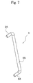
- FIG. 7 is a perspective external view of the guide rod 6.
- the guide rod 6 has such a shape that both ends thereof are bent to each have a 90-degree angle.
- the guide rod 6 has two bending shafts 6A and 6A, and one of the bending shafts 6A serves as a follower member of the heart cam channel 4A of FIG. 2, and the other bending shaft 6A is engaged with the shaft hole 14A of FIG. 4.
- the guide rod 6 can freely swing about the shaft hole 14A, and a middle shaft section 6B thereof is pressed against the pressing piece 2C of FIG. 3.
- FIG. 8 is a plan view of the connector 100 before attached with the memory card 10.
- the swing slider 4 is biased by the tensile coil spring 5 in the direction of arrow R.
- the swing slider 4 does not move any further in the direction of arrow R because the guide rod 6 is latched into the heart cam channel 4A.
- the second lug 42 of the swing slider 4 is so placed as to protrude from the guide wall 11A to abut the side surface of the memory card 10.
- FIG. 9 is a view of the connector 100.
- FIG. 9 shows the state in which the memory card 10 is inserted into the connector 100, and the slanting section of the memory card 10 on its side surface is abutting the slope section of the second lug 42.
- the corner part of the memory card 10 on the insertion side is not abutting the first lug 41.
- the memory card 10 is inserted into the connector 100 in such a manner that the connector terminals come upside.
- FIG. 10 is a plan view of the connector 100.
- FIG. 10 shows the state in which the side surface of the memory card 10 is pushing up the second lug 42 against the biasing force of the tensile coil spring 5.
- the swing slider 4 is rotating counterclockwise about the cylindrical protrusion 13A (refer to FIG. 4) formed to the first guide 13.
- FIG. 11 is a plan view of the connector 100.
- the second lug 42 engages with the concave section 10Aby sliding over the slanting section of the memory card 10 on its side surface.
- the corner part of the memory card 10 on the insertion side is abutting the first lug 41.
- the swing slider 4 rotates clockwise by the biasing force of the tensile coil spring 5, and returns to the same position and posture as FIG. 9. If the memory card 10 is inserted a little more in the direction of arrow F against the biasing force of the tensile coil spring 5, it will result in the insertion state of FIG. 12.
- FIG. 12 is a plan view of the connector 100.
- the swing slider 4 moves parallel following the first and second guides 13 and 14. Then, the swing slider 4 follows the movement of the memory card 10 to be inserted.
- one bending shaft 6A of the guide rod 6 is moving toward the V-shaped groove 4V formed to the heart cam channel 4A.
- the swing slider 4 is biased to move in the direction of arrow R by the tensile coil spring 5. However, the swing slider 4 is fixed in position due to the guide rod 6 latched into the V-shaped groove 4V.
- FIG. 12 shows the insertion state of the memory card 10.
- the connector terminals on the memory card 10 are contacting with the cantilever contacts 3, thereby allowing data reading and writing from/to the memory card 10.
- the second lug 42 is engaging with the concave section 10A, and thus the memory card 10 is not easily popped out from the connector 100 even with vibration if occurred.
- the memory card 10 can favorably remain inserted.
- the memory card 10 moves in the direction of arrow R by the biasing force of the tensile coil spring 5, and is put into the state of FIG. 13. That is, by being pushed toward the first lug 41, the memory card 10 moves in the not-insertion direction, that is, in the ejection direction.
- FIG. 13 is a plan view of the connector 100.
- the position relationship between the connector 100 and the memory card 10, and the state of the lock mechanism 1R are both put back to the same as those of FIG. 1. Even moved, the memory card 10 never accidentally pop out from the connector 100, because the second lug 42 remains engaged with the concave section 10 of the memory card 10.
- the second lug 42 biased by the tensile coil spring 5 pulls the card memory 10 with such a strong force as sliding over from the concave section 10A.
- the memory card 10 can be ejected from the connector 10.
- FIGS. 14A to 14E described next is the action of the swing slider 4 including the heart cam channel 4A.
- FIG. 14A is a plane view of the swing slider 4
- FIG. 14B is a cross sectional view cut along a B-B line of FIG. 14A.
- FIG. 14C is a cross sectional view cut along a C-C line of FIG. 14A.
- FIG. 14D is a cross sectional view cut along a D-D line of FIG. 14A.
- FIG. 14E is a cross sectional view cut along an E-E line of FIG. 14A.
- the cam system includes the swing slider 4 provided with the heart cam channel 4A as a cam serving as a moving member, and the guide rod 6 (refer to FIG. 2) as a follower member.
- the moving member and the follower member of the cam system relatively change in position.
- the point where the swing slider 4 and the guide rod 6 are contacting will draw a plane curve, i.e., trail of heart.
- This contact point also draws a space curve of the continuous trail of the cam channel 4A whose bottom surface is changed in level or sloped.
- the swing slider 4 and the guide rod 6 are structuring a so-called three-dimensional cam system.
- the cam channel 4A starts to trail by the bending shaft 6A of the guide rod 6, and the bottom surface A1 is a plane parallel to the bottom surface of the swing slider 4.
- a bottom surface A2 is sloped upward from the bottom surface A1.
- the bending shaft 6A After the bending shaft 6Apasses the slopedbottom surface A2, the bending shaft 6A reaches a bottom surface A3 locating upper than the bottom surface A1. After the bending shaft 6A passes the bottom surface A3, the plane is changed in level, and the bending shaft 6A reaches a bending bottom surface 4A locating lower than the bottom surface A3. That is, in the process of state change from FIG. 11 to 12, i.e., in the process that the bending shaft 6A (refer to FIG. 12) of the guide rod 6 moves, once reached the bottom surface A4, the bending shaft 6A cannot return therefrom to the bottom surface A3.
- a bottom surface A7 adjacent to the bottom surface A6, formed is a bottom surface A7 that is sloped upward from the bottom surface A6.
- the bending shaft 6A passes the sloped bottom surface A7, the bending shaft 6A reaches a bottom surface A8 locating upper than the bottom surface A6.
- the plane is changed in level, and the bending shaft 6A returns to the bottom surface A1 locating lower than the bottom surface A8.
- the contact point between the cam channel 4A and the guide rod 6 draws a planar trail of a heart, and in the height direction, draws a trail partially irreversible.
- a second lug remains engaged with the concave section of the memory card, so that the second lug prevent a memory card from accidentally popping out from a connector on the way toward a card insertion port for ejection from the connector.
Landscapes
- Physics & Mathematics (AREA)
- General Physics & Mathematics (AREA)
- Engineering & Computer Science (AREA)
- Theoretical Computer Science (AREA)
- Coupling Device And Connection With Printed Circuit (AREA)
- Connection Of Plates (AREA)
- Details Of Connecting Devices For Male And Female Coupling (AREA)
Applications Claiming Priority (2)
| Application Number | Priority Date | Filing Date | Title |
|---|---|---|---|
| JP2003296730A JP3859626B2 (ja) | 2003-08-20 | 2003-08-20 | メモリカード用コネクタ |
| JP2003296730 | 2003-08-20 |
Publications (2)
| Publication Number | Publication Date |
|---|---|
| EP1508873A1 true EP1508873A1 (fr) | 2005-02-23 |
| EP1508873B1 EP1508873B1 (fr) | 2008-10-22 |
Family
ID=34056234
Family Applications (1)
| Application Number | Title | Priority Date | Filing Date |
|---|---|---|---|
| EP04019691A Expired - Lifetime EP1508873B1 (fr) | 2003-08-20 | 2004-08-19 | Connecteur de carte mémoire |
Country Status (7)
| Country | Link |
|---|---|
| US (1) | US7070452B2 (fr) |
| EP (1) | EP1508873B1 (fr) |
| JP (1) | JP3859626B2 (fr) |
| KR (1) | KR101035466B1 (fr) |
| CN (1) | CN100370655C (fr) |
| DE (1) | DE602004017262D1 (fr) |
| TW (1) | TWI327800B (fr) |
Cited By (3)
| Publication number | Priority date | Publication date | Assignee | Title |
|---|---|---|---|---|
| WO2007110100A1 (fr) * | 2006-03-29 | 2007-10-04 | Fci | Lecteur de carte dote d'un mecanisme d'ejection de carte |
| WO2007145952A3 (fr) * | 2006-06-05 | 2008-02-21 | Molex Inc | Connecteur de carte à double came |
| WO2008105621A1 (fr) * | 2007-02-27 | 2008-09-04 | Jung, Min-Jo | Came à curseur de récepteur de cartes |
Families Citing this family (15)
| Publication number | Priority date | Publication date | Assignee | Title |
|---|---|---|---|---|
| US6981885B2 (en) * | 2001-12-11 | 2006-01-03 | Molex Incorporated | Secure digital memory card socket |
| DE102004040448B4 (de) * | 2004-08-20 | 2010-01-21 | Amphenol-Tuchel Electronics Gmbh | Pushmatic Smart Card Connector |
| JP2006324185A (ja) * | 2005-05-20 | 2006-11-30 | Union Machinery Co Ltd | カードコネクタ |
| JP4694340B2 (ja) * | 2005-10-03 | 2011-06-08 | モレックス インコーポレイテド | カード用コネクタ |
| JP4906312B2 (ja) * | 2005-10-24 | 2012-03-28 | モレックス インコーポレイテド | カード用コネクタ |
| JP2008053124A (ja) | 2006-08-25 | 2008-03-06 | Jst Mfg Co Ltd | カード用コネクタ |
| US7626826B2 (en) * | 2007-01-31 | 2009-12-01 | Sun Microsystems, Inc. | Expansion card carrier and method for assembling the same |
| US7314389B1 (en) * | 2007-02-06 | 2008-01-01 | Northstar Systems Corp. | Electronic card connector |
| TWI337319B (en) * | 2007-06-27 | 2011-02-11 | Asustek Comp Inc | Mobile communication apparatus and input module thereof |
| JP2009176510A (ja) * | 2008-01-23 | 2009-08-06 | Honda Tsushin Kogyo Co Ltd | メモリーカード用コネクタ |
| KR100978511B1 (ko) * | 2008-04-18 | 2010-08-27 | (주)우주일렉트로닉스 | 카드용 커넥터 |
| US7632117B1 (en) * | 2008-07-17 | 2009-12-15 | Hon Hai Precision Ind. Co., Ltd. | Card connector with ejecting member |
| JP2010123543A (ja) | 2008-11-21 | 2010-06-03 | Jst Mfg Co Ltd | カード用コネクタ |
| JP5623204B2 (ja) * | 2010-09-08 | 2014-11-12 | 日本圧着端子製造株式会社 | カード用コネクタ |
| TWM405658U (en) * | 2010-11-22 | 2011-06-11 | Tyco Electronics Holdings Bermuda No 7 Ltd | Card edge connector |
Citations (2)
| Publication number | Priority date | Publication date | Assignee | Title |
|---|---|---|---|---|
| WO2002007269A2 (fr) * | 2000-06-29 | 2002-01-24 | Molex Incorporated | Connecteur de cartes a circuit integre |
| EP1293929A1 (fr) * | 2001-09-12 | 2003-03-19 | Mitsumi Electric Co., Ltd. | Connecteur de carte à mémoire ayant un mécanisme de blocage s'engageant dans un renfoncement de la carte |
Family Cites Families (15)
| Publication number | Priority date | Publication date | Assignee | Title |
|---|---|---|---|---|
| JP3559319B2 (ja) | 1994-09-29 | 2004-09-02 | 株式会社東芝 | Icカード情報処理装置 |
| JP3074462B2 (ja) | 1995-10-19 | 2000-08-07 | 日本航空電子工業株式会社 | 多芯コネクタ駆動機構 |
| JP3435384B2 (ja) | 2000-04-10 | 2003-08-11 | Smk株式会社 | メモリーカード用コネクタ |
| JP2002015820A (ja) | 2000-06-30 | 2002-01-18 | Mitsumi Electric Co Ltd | メモリカード用コネクタ |
| JP2002110297A (ja) | 2000-09-29 | 2002-04-12 | Mitsumi Electric Co Ltd | メモリカード用コネクタ |
| JP2002124343A (ja) | 2000-10-13 | 2002-04-26 | Omron Corp | メモリカード用コネクタ |
| JP3455176B2 (ja) | 2000-11-16 | 2003-10-14 | 株式会社アドバネクス | 記憶媒体内蔵板状体ホルダ |
| JP2003006576A (ja) | 2001-06-26 | 2003-01-10 | Matsushita Electric Works Ltd | メモリカード用ソケット |
| JP3783591B2 (ja) * | 2001-09-07 | 2006-06-07 | オムロン株式会社 | メモリカード用コネクタ |
| JP2003086289A (ja) * | 2001-09-10 | 2003-03-20 | Alps Electric Co Ltd | カード用コネクタ装置 |
| JP4012708B2 (ja) * | 2001-09-17 | 2007-11-21 | アルプス電気株式会社 | カード用コネクタ装置 |
| JP3775338B2 (ja) | 2001-11-15 | 2006-05-17 | 松下電工株式会社 | メモリカード用コネクタ装置及びその製造方法 |
| JP2003187904A (ja) | 2001-12-20 | 2003-07-04 | Honda Tsushin Kogyo Co Ltd | カードアダプタ |
| JP3830852B2 (ja) * | 2002-04-15 | 2006-10-11 | アルプス電気株式会社 | カード用コネクタ装置 |
| CN2554818Y (zh) * | 2002-06-25 | 2003-06-04 | 富士康(昆山)电脑接插件有限公司 | 电子卡连接器 |
-
2003
- 2003-08-20 JP JP2003296730A patent/JP3859626B2/ja not_active Expired - Fee Related
-
2004
- 2004-08-19 DE DE602004017262T patent/DE602004017262D1/de not_active Expired - Lifetime
- 2004-08-19 EP EP04019691A patent/EP1508873B1/fr not_active Expired - Lifetime
- 2004-08-19 KR KR1020040065273A patent/KR101035466B1/ko not_active Expired - Fee Related
- 2004-08-19 US US10/921,338 patent/US7070452B2/en not_active Expired - Fee Related
- 2004-08-20 TW TW093125189A patent/TWI327800B/zh not_active IP Right Cessation
- 2004-08-20 CN CNB2004100582579A patent/CN100370655C/zh not_active Expired - Fee Related
Patent Citations (2)
| Publication number | Priority date | Publication date | Assignee | Title |
|---|---|---|---|---|
| WO2002007269A2 (fr) * | 2000-06-29 | 2002-01-24 | Molex Incorporated | Connecteur de cartes a circuit integre |
| EP1293929A1 (fr) * | 2001-09-12 | 2003-03-19 | Mitsumi Electric Co., Ltd. | Connecteur de carte à mémoire ayant un mécanisme de blocage s'engageant dans un renfoncement de la carte |
Cited By (4)
| Publication number | Priority date | Publication date | Assignee | Title |
|---|---|---|---|---|
| WO2007110100A1 (fr) * | 2006-03-29 | 2007-10-04 | Fci | Lecteur de carte dote d'un mecanisme d'ejection de carte |
| WO2007145952A3 (fr) * | 2006-06-05 | 2008-02-21 | Molex Inc | Connecteur de carte à double came |
| US7997913B2 (en) | 2006-06-05 | 2011-08-16 | Molex Incorporated | Card connector with double cam |
| WO2008105621A1 (fr) * | 2007-02-27 | 2008-09-04 | Jung, Min-Jo | Came à curseur de récepteur de cartes |
Also Published As
| Publication number | Publication date |
|---|---|
| KR101035466B1 (ko) | 2011-05-18 |
| JP2005071667A (ja) | 2005-03-17 |
| TW200527771A (en) | 2005-08-16 |
| EP1508873B1 (fr) | 2008-10-22 |
| TWI327800B (en) | 2010-07-21 |
| KR20050020670A (ko) | 2005-03-04 |
| CN1585197A (zh) | 2005-02-23 |
| US20050101174A1 (en) | 2005-05-12 |
| CN100370655C (zh) | 2008-02-20 |
| JP3859626B2 (ja) | 2006-12-20 |
| US7070452B2 (en) | 2006-07-04 |
| DE602004017262D1 (de) | 2008-12-04 |
Similar Documents
| Publication | Publication Date | Title |
|---|---|---|
| EP1508873B1 (fr) | Connecteur de carte mémoire | |
| US7077705B2 (en) | Memory card connector | |
| JP4351826B2 (ja) | カード用コネクタ装置 | |
| US7381094B2 (en) | Card connector | |
| JP3823038B2 (ja) | カード用コネクタ装置 | |
| US6790061B1 (en) | Two-stage ejection mechanism of card connector | |
| US20040087194A1 (en) | Compound connector for two different types of electronic packages | |
| US20060014436A1 (en) | Memory card connector | |
| JP5329152B2 (ja) | カード用コネクタ | |
| US20050159035A1 (en) | Lift-up mini secure digital card connector | |
| JP2004259051A (ja) | カード用コネクタ装置 | |
| JP4268059B2 (ja) | カード用コネクタ装置 | |
| CN101728674B (zh) | 卡用连接器 | |
| JP4425715B2 (ja) | カード用コネクタ装置 | |
| JP3827578B2 (ja) | カード用コネクタ装置 | |
| KR101076652B1 (ko) | 커넥터 및 검출 스위치 | |
| JP2002151205A (ja) | カード用コネクタ装置 | |
| JP2004311123A (ja) | カード用コネクタ装置 | |
| US20090275238A1 (en) | Electrical card connector with a metal retention mechanism | |
| JP2003229207A (ja) | カード用コネクタ装置 | |
| JP2001236471A (ja) | 記録媒体差込み用コネクタ |
Legal Events
| Date | Code | Title | Description |
|---|---|---|---|
| PUAI | Public reference made under article 153(3) epc to a published international application that has entered the european phase |
Free format text: ORIGINAL CODE: 0009012 |
|
| AK | Designated contracting states |
Kind code of ref document: A1 Designated state(s): AT BE BG CH CY CZ DE DK EE ES FI FR GB GR HU IE IT LI LU MC NL PL PT RO SE SI SK TR |
|
| AX | Request for extension of the european patent |
Extension state: AL HR LT LV MK |
|
| 17P | Request for examination filed |
Effective date: 20050523 |
|
| AKX | Designation fees paid |
Designated state(s): DE FR GB |
|
| GRAP | Despatch of communication of intention to grant a patent |
Free format text: ORIGINAL CODE: EPIDOSNIGR1 |
|
| GRAS | Grant fee paid |
Free format text: ORIGINAL CODE: EPIDOSNIGR3 |
|
| GRAA | (expected) grant |
Free format text: ORIGINAL CODE: 0009210 |
|
| AK | Designated contracting states |
Kind code of ref document: B1 Designated state(s): DE FR GB |
|
| REG | Reference to a national code |
Ref country code: GB Ref legal event code: FG4D |
|
| REF | Corresponds to: |
Ref document number: 602004017262 Country of ref document: DE Date of ref document: 20081204 Kind code of ref document: P |
|
| PLBE | No opposition filed within time limit |
Free format text: ORIGINAL CODE: 0009261 |
|
| STAA | Information on the status of an ep patent application or granted ep patent |
Free format text: STATUS: NO OPPOSITION FILED WITHIN TIME LIMIT |
|
| 26N | No opposition filed |
Effective date: 20090723 |
|
| GBPC | Gb: european patent ceased through non-payment of renewal fee |
Effective date: 20090819 |
|
| PG25 | Lapsed in a contracting state [announced via postgrant information from national office to epo] |
Ref country code: GB Free format text: LAPSE BECAUSE OF NON-PAYMENT OF DUE FEES Effective date: 20090819 |
|
| PGFP | Annual fee paid to national office [announced via postgrant information from national office to epo] |
Ref country code: DE Payment date: 20100830 Year of fee payment: 7 Ref country code: FR Payment date: 20100819 Year of fee payment: 7 |
|
| REG | Reference to a national code |
Ref country code: FR Ref legal event code: ST Effective date: 20120430 |
|
| REG | Reference to a national code |
Ref country code: DE Ref legal event code: R119 Ref document number: 602004017262 Country of ref document: DE Effective date: 20120301 |
|
| PG25 | Lapsed in a contracting state [announced via postgrant information from national office to epo] |
Ref country code: FR Free format text: LAPSE BECAUSE OF NON-PAYMENT OF DUE FEES Effective date: 20110831 |
|
| PG25 | Lapsed in a contracting state [announced via postgrant information from national office to epo] |
Ref country code: DE Free format text: LAPSE BECAUSE OF NON-PAYMENT OF DUE FEES Effective date: 20120301 |