EP1508948A2 - Modulares Niederspannungs-Raumionisierungssystem - Google Patents
Modulares Niederspannungs-Raumionisierungssystem Download PDFInfo
- Publication number
- EP1508948A2 EP1508948A2 EP04022890A EP04022890A EP1508948A2 EP 1508948 A2 EP1508948 A2 EP 1508948A2 EP 04022890 A EP04022890 A EP 04022890A EP 04022890 A EP04022890 A EP 04022890A EP 1508948 A2 EP1508948 A2 EP 1508948A2
- Authority
- EP
- European Patent Office
- Prior art keywords
- emitter
- lines
- system controller
- emitter module
- modules
- Prior art date
- Legal status (The legal status is an assumption and is not a legal conclusion. Google has not performed a legal analysis and makes no representation as to the accuracy of the status listed.)
- Granted
Links
- 238000004891 communication Methods 0.000 claims abstract description 57
- 230000000694 effects Effects 0.000 claims abstract description 7
- 238000001514 detection method Methods 0.000 claims abstract description 5
- 230000008859 change Effects 0.000 claims description 4
- 230000002441 reversible effect Effects 0.000 abstract description 2
- 230000007257 malfunction Effects 0.000 abstract 1
- 150000002500 ions Chemical class 0.000 description 115
- 238000000034 method Methods 0.000 description 31
- 238000005259 measurement Methods 0.000 description 17
- 238000010586 diagram Methods 0.000 description 15
- 238000012544 monitoring process Methods 0.000 description 9
- 230000008569 process Effects 0.000 description 8
- 230000006870 function Effects 0.000 description 5
- 230000003068 static effect Effects 0.000 description 5
- 230000000977 initiatory effect Effects 0.000 description 4
- 230000015556 catabolic process Effects 0.000 description 3
- 230000007812 deficiency Effects 0.000 description 3
- 238000006731 degradation reaction Methods 0.000 description 3
- 238000009434 installation Methods 0.000 description 3
- 238000004519 manufacturing process Methods 0.000 description 3
- 230000001360 synchronised effect Effects 0.000 description 3
- 230000009471 action Effects 0.000 description 2
- 230000008901 benefit Effects 0.000 description 2
- 239000004020 conductor Substances 0.000 description 2
- 230000001419 dependent effect Effects 0.000 description 2
- 238000012986 modification Methods 0.000 description 2
- 230000004048 modification Effects 0.000 description 2
- 239000012811 non-conductive material Substances 0.000 description 2
- 239000002245 particle Substances 0.000 description 2
- 238000012935 Averaging Methods 0.000 description 1
- 238000004566 IR spectroscopy Methods 0.000 description 1
- 230000005540 biological transmission Effects 0.000 description 1
- 239000000969 carrier Substances 0.000 description 1
- 238000011109 contamination Methods 0.000 description 1
- 238000012937 correction Methods 0.000 description 1
- 230000003247 decreasing effect Effects 0.000 description 1
- 230000007547 defect Effects 0.000 description 1
- 230000000994 depressogenic effect Effects 0.000 description 1
- 238000003745 diagnosis Methods 0.000 description 1
- 230000005684 electric field Effects 0.000 description 1
- 238000010304 firing Methods 0.000 description 1
- 239000012212 insulator Substances 0.000 description 1
- 238000006386 neutralization reaction Methods 0.000 description 1
- 238000013021 overheating Methods 0.000 description 1
- 230000000737 periodic effect Effects 0.000 description 1
- 238000003825 pressing Methods 0.000 description 1
- 230000009467 reduction Effects 0.000 description 1
- 239000004065 semiconductor Substances 0.000 description 1
- 235000012431 wafers Nutrition 0.000 description 1
Images





Classifications
-
- H—ELECTRICITY
- H01—ELECTRIC ELEMENTS
- H01T—SPARK GAPS; OVERVOLTAGE ARRESTERS USING SPARK GAPS; SPARKING PLUGS; CORONA DEVICES; GENERATING IONS TO BE INTRODUCED INTO NON-ENCLOSED GASES
- H01T23/00—Apparatus for generating ions to be introduced into non-enclosed gases, e.g. into the atmosphere
Definitions
- Controlling static charge is an important issue in semiconductor manufacturing because of its significant impact on the device yields. Device defects caused by electrostatically attracted foreign matter and electrostatic discharge events contribute greatly to overall manufacturing losses. Many of the processes for producing integrated circuits use non-conductive materials which generate large static charges and complimentary voltage on wafers and devices.
- Air ionization is the most effective method of eliminating static charges on non-conductive materials and isolated conductors.
- Air ionizers are known e.g. from US 4 809 127 and US 4 757 422. Air ionizers generate large quantities of positive and negative ions in the surrounding atmosphere which serve as mobile carriers of charge in the air. As ions flow through the air, they are attracted to oppositely charged particles and surfaces. Neutralization of electrostatically charged surfaces can be rapidly achieved through the process.
- Air ionization may be performed using electrical ionizers which generate ions in a process known as corona discharge. Electrical ionizers generate air ions through this process by intensifying an electric field around a sharp point until it overcomes the dielectric strength of the surrounding air. Negative corona occurs when electrons are flowing from the electrode into the surrounding air. Positive corona occurs as a result of the flow of electrons from the air molecules into the electrode.
- the ionizer To achieve the maximum possible reduction in static charges from an ionizer of a given output, the ionizer must produce equal amounts of positive and negative ions. That is, the output of the ionizer must be "balanced.” If the ionizer is out of balance, the isolated conductor and insulators can become charged such that the ionizer creates more problems than it solves. Ionizers may become imbalanced due to power supply drift, power supply failure of one polarity, contamination of electrodes, or degradation of electrodes. In addition, the output of an ionizer may be balanced, but the total ion output may drop below its desired level due to system component degradation.
- ionization systems incorporate monitoring, automatic balancing via feedback systems, and alarms for detecting uncorrected imbalances and out-of-range outputs.
- Most feedback systems are entirely or primarily hardware-based. Many of these feedback systems cannot provide very fine balance control, since feedback control signals are fixed based upon hardware component values. Furthermore, the overall range of balance control of such hardware-based feedback systems may be limited based upon the hardware component values. Also, many of the hardware-based feedback systems cannot be easily modified since the individual components are dependent upon each other for proper operation.
- a charged plate monitor is typically used to calibrate and periodically measure the actual balance of an electrical ionizer, since the actual balance in the work space may be different from the balance detected by the ionizer's sensor.
- the charged plate monitor is also used to periodically measure static charge decay time. If the decay time is too slow or too fast, the ion output may be adjusted by increasing or decreasing the preset ion current value. This adjustment is typically performed by adjusting two trim potentiometers (one for positive ion generation and one for negative ion generation). Periodic decay time measurements are necessary because actual ion output in the work space may not necessarily correlate with the expected ion output for the ion output current value set in the ionizer. For example, the ion output current may be initially set at the factory to a value (e.g., 0.6 ⁇ A) so as to produce the desired amount of ions per unit time.
- a value e.g., 0.6 ⁇ A
- the ionizer high voltage power supply is adjusted to restore the initial value of ion current.
- a room ionization system typically includes a plurality of electrical ionizers connected to a single controller.
- Fig. 1 shows a conventional room ionization system 10 which includes a plurality of ceiling-mounted emitter modules 12 1 -12 n (also, referred to as "pods") connected in a daisy-chain manner by signal lines 14 to a controller 16.
- Each emitter module 12 includes an electrical ionizer 18 and communications/control circuitry 20 for performing limited functions, including the following functions:
- the signal line 14 has four lines; power, ground, alarm and ON/OFF control.
- the alarm signal which is transmitted on the alarm line does not include any information regarding the identification of the malfunctioning emitter module 12 .
- the controller 16 does not know which emitter module 12 has malfunctioned when an alarm signal is received.
- the alarm signal does not identify the type of problem (e.g., bad negative or positive emitter, balance off).
- the process of identifying which emitter module 12 sent the alarm signal and what type of problem exists is time-consuming.
- the signal lines 14 between respective emitter modules 12 consist of a plurality of wires with connectors crimped, soldered, or otherwise attached, at each end.
- the connectors are attached in the field (i.e., during installation) since the length of the signal line 14 may vary between emitter modules 12 . That is, the length of the signal line 14 between emitter module 12 1 and 12 2 may be different from the length of the signal line 14 between emitter module 12 3 and 12 4 .
- the signal lines 14 may be set to exactly the right length, thereby resulting in a cleaner installation.
- the conventional room ionization system 10 may be either a high voltage or low voltage system.
- a high voltage is generated at the controller 16 and is distributed via power cables to the plurality of emitter modules 12 for connection to the positive and negative emitters.
- a low voltage is generated at the controller 16 and is distributed to the plurality of emitter modules 12 where the voltage is stepped up to the desired high voltage for connection to the positive and negative emitters.
- the voltage may be AC or DC. If the voltage is DC, it may be either steady state DC or pulse DC.
- Each type of voltage has advantages and disadvantages.
- a linear regulator is typically used for the emitter-based low voltage power supply. Since the current passing through a linear regulator is the same as the current at its output, a large voltage drop across the linear regulator (e.g., 25 V drop caused by 30 V in/5 V out) causes the linear regulator to draw a significant amount of power, which, in turn, generates a significant amount of heat. Potential overheating of the linear regulator thus limits the input voltage, which in turn, limits the amount of emitter modules that can be connected to a single controller 16 . Also, since the power lines are not lossless, any current in the line causes a voltage drop across the line.
- the net effect is that when linear regulators are used in the emitter modules 12 , the distances between successive daisy-chained emitter modules 12 , and the distance between the controller 16 and the emitter modules 12 must be limited to ensure that all emitter modules 12 receive sufficient voltage to drive the module-based high voltage power supplies.
- Methods and devices are provided for balancing positive and negative ion output in an electrical ionizer having positive and negative ion emitters and positive and negative high voltage power supplies associated with the respective positive and negative ion emitters.
- a balance reference value is stored in a software-adjustable memory.
- the balance reference value is compared to a balance measurement value taken by an ion balance sensor located close to the ion emitters.
- At least one of the positive and negative high voltage power supplies are automatically adjusted if the balance reference value is not equal to the balance measurement value. The adjustment is performed in a manner which causes the balance measurement value to become equal to the balance reference value.
- the actual ion balance is measured in the work space near the electrical ionizer using a charged plate monitor.
- the balance reference value is adjusted if the actual balance measurement shows that the automatic ion balance scheme is not providing a true balanced condition.
- Similar methods and devices are provided for controlling ion output current, wherein an ion output current reference value is stored in a software-adjustable memory, the ion output current reference value is compared to an actual ion current value taken by current metering circuitry within the electrical ionizer, and automatic adjustments are made to maintain a desired ion output current.
- the decay time is measured in the work space near the electrical ionizer using a charged plate monitor.
- the ion output current reference value is adjusted if the decay time is too slow or too fast, which in turn, causes the actual ion output current to increase or decrease to match the new ion output current reference value.
- Both the balance reference value and the ion output current reference value may be adjusted by a remote control device or by a system controller connected to the electrical ionizer.
- the present invention also provides an ionization system for a predefined area comprising a plurality of emitter modules spaced around the area, a system controller for controlling the emitter modules, and electrical lines for electrically connecting the plurality of emitter modules with the system controller in a daisy-chain manner, wherein the electrical lines provide both communication with, and power to, the emitter modules.
- each emitter module has an individual address and the system controller individually addresses and controls each emitter module.
- the balance reference value and ion output current reference value of each emitter module may be individually adjusted, either by the system controller or by a remote control transmitter.
- miswire protection circuitry is provided in each emitter module to automatically change the relative position of the electrical lines which enter each emitter module upon detection of a miswired condition.
- each emitter module is provided with a switching power supply to minimize the effects of line loss on the electrical lines.
- a power mode setting is provided for setting each emitter module in one of a plurality of different operating power modes.
- the present invention also provides a circuit for changing the relative position of wired electrical lines which are in a fixed relationship to each other, wherein the wired electrical lines include a first communication line and a second communication line.
- the circuit comprises a first switch associated with the first communication line, a second switch associated with the second communication line, and a processor having an output control signal connected to the first and second switches.
- the first switch has a first, initial position and a second position which is opposite of the first, initial position.
- the second switch has a first, initial position and a second position which is opposite of the first, initial position.
- the output control signal of the processor causes the first and second switches to be placed in their respective first or second position, wherein the first and second communication lines have a first configuration when both are in their first, initial position and a second configuration when both are in their second position.
- Fig. 2 is a modular room ionization system 22 in accordance with the present invention.
- the system 22 includes a plurality of ceiling-mounted emitter modules 24 1 -24 n connected in a daisy-chain manner by RS-485 communication/power lines 26 to a system controller 28.
- a maximum of ten emitter modules 24 are daisy-chained to a single system controller 28 , and successive emitter modules 24 are about 7-12 feet apart from each other.
- Each emitter module 24 includes an electrical ionizer and communications/control circuitry, both of which are illustrated in more detail in Fig. 4.
- the system 22 also includes an infrared (IR) remote control transmitter 30 for sending commands to the emitter modules 24 .
- the circuitry of the transmitter 30 is shown in more detail in Figs. 3A and 3B.
- the circuitry of the system controller 28 is shown in more detail in Fig. 6.
- the system 22 provides improved capabilities over conventional systems, such as shown in Fig. 1. Some of the improved capabilities are as follows:
- Fig. 3A shows a schematic block diagram of the remote control transmitter 30.
- the transmitter 30 includes two rotary encoding switches 32, four pushbutton switches 34, a 4:2 demultiplexer 36, a serial encoder 38, a frequency modulator 40 and an IR drive circuit 42 .
- the rotary encoder switches 32 are used to produce seven binary data lines that are used to "address" the individual emitter modules 24 .
- the four pushbutton switches 34 are used to connect power to the circuitry and create a signal that passes through the 4:2 demultiplexer 36 .
- the 4:2 demultiplexer 36 comprises two 2 input NAND gates and one 4 input NAND gate. Unlike a conventional 4:2 demultiplexer which produces two output signals, the demultiplexer 36 produces three output signals, namely, two data lines and one enable line.
- the "enable" signal (which is not produced by a conventional 4:2 demultiplexer), is produced when any of the four inputs are pulled low as a result of a pushbutton being depressed. This signal is used to turn on a LED, and to enable the encoder and modulator outputs.
- the modulator 40 receives the enable line from the demultiplexer 36 and the serial data from the encoder 38 , and creates a modulated signal. The modulated signal is then passed to the IR diode driver for transmitting the IR information.
- Fig. 3B is a circuit level diagram of Fig. 3A.
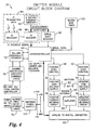
- Fig. 4 shows a schematic block diagram of one emitter module 24 .
- the emitter module 24 performs at least the following three basis functions; produce and monitor ions, communicate with the system controller 28 , and receive IR data from the transmitter 30 .
- the emitter module 24 produces ions using a closed loop topology including three input paths and two output paths. Two of the three input paths monitor the positive and negative ion current and include a current metering circuit 56 or 58 , a multi-input A/D converter 60 , and the microcontroller 44.
- the third input path monitors the ion balance and includes a sensor antenna 66 , an amplifier 68 , the multi-input A/D converter 60 , and the microcontroller 44 .
- the two output paths control the voltage level of the high-voltage power supplies 52 or 54 and include the microcontroller 44, a digital potentiometer (or D/A converter as a substitute therefor), an analog switch, high-voltage power supply 52 or 54 , and an output emitter 62 or 64.
- the digital potentiometer and the analog switch are part of the level control 48 or 50 .
- the microcontroller 44 holds a reference ion output current value, C REF , obtained from the system controller 28. The microcontroller 44 then compares this value with a measured or actual value, C MEAS , read from the A/D converter 60 . The measured value is obtained by averaging the positive and negative current values. If C MEAS is different than C REF , the microcontroller 44 instructs the digital potentiometers (or D/A's) associated with the positive and negative emitters to increase or decrease their output by the same, or approximately the same, amount.
- the analog switches of the positive level controls 48, 50 are controlled by the microcontroller 44 which turns them on constantly for steady state DC ionization, or oscillates the switches at varying rates, depending upon the mode of the emitter module.
- the output signals from the analog switches are then passed to the positive and negative high voltage power supplies 52, 54 .
- the high voltage power supplies 52 , 54 take in the DC signals and produce a high voltage potential on the ionizing emitter points 62, 64.
- the return path for the high voltage potential is connected to the positive or negative current metering circuits 56, 58 .
- the current metering circuits 56, 58 amplify the voltage produced when the high voltage supplies 52, 54 draw a current through a resistor.
- the high voltage return circuits then pass this signal to the A/D converter 60 (which has four inputs for this purpose).
- the A/D converter 60 When requested by the microcontroller 44 , the A/D converter 60 produces a serial data stream that corresponds to the voltage level produced by the high voltage return circuit. The microcontroller 44 then compares these values with the programmed values and makes adjustments to the digital potentiometers discussed above.
- Ion balance of the emitter module 24 is performed using a sensor antenna 66 , an amplifier 68 (such as one having a gain of 34.2), a level adjuster (not shown), and the A/D converter 60 .
- the sensor antenna 66 is placed between the positive and negative emitters 62, 64 , such as equidistant therebetween. If there is an imbalance in the emitter module 24 , a charge will build up on the sensor antenna 66 . The built-up charge is amplified by the amplifier 68. The amplified signal is level shifted to match the input range of the A/D converter 60 , and is then passed to the A/D converter 60 for use by the microcontroller 44 .
- a communication circuit disposed between the microcontroller 44 and the system controller 28 includes a miswire protection circuit 70 and a RS-485 encoder/decoder 72.
- the miswire protection circuit allows the emitter module 24 to function normally even if an installer accidentally inverts (i.e., flips or reverses) the wiring connections when attaching the connectors to the communication/power line 26 .
- the microcontroller 44 sets two switches on and reads the RS-485 line. From this initial reading, the microcontroller 44 determines if the communication/power line 26 is in an expected state. If the communication/power line 26 is in the expected state and remains in the expected state for a predetermined period of time, then the communication lines of the communication/power line 26 is not flipped and program in the microcontroller 44 proceeds to the next step.
- switches associated with the miswire protection circuit 70 are reversed to electronically flip the communication lines of the communication/power line 26 to the correct position. Once the communication/power line 26 is corrected, then the path for the system controller 28 to communicate with the emitter module 24 is operational. A full-wave bridge is provided to automatically orient the incoming power to the proper polarity.
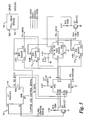
- Fig. 5 is a circuit level diagram of the miswire protection circuit 70. Reversing switches 74 1 and 74 2 electronically flip the communication line, and full-wave bridge 76 flips the power lines. In one preferred four wire ordering scheme, the two RS-485 communication lines are on the outside, and the two power lines are on the inside.
- the microcontroller 44 in the emitter module 24 needs to retrieve the "address" from the emitter module address circuit.
- the "address" of the emitter module is set at the installation by adjustment of two rotary encoder switches 90 located on the emitter module 24 .
- the microcontroller 44 gets the address from the rotary encoder switches 90 and a serial shift register 92 .
- the rotary encoder switches 90 provide seven binary data lines to the serial shift register 92 .
- the microcontroller 44 shifts in the switch settings serially to determine the "address” and stores this within its memory.
- the emitter module 24 includes an IR receive circuit 94 which includes an IR receiver 96 , an IR decoder 98 , and the two rotary encoder switches 90 .
- the IR receiver 96 strips the carrier frequency off and leaves only a serial data stream which is passed to the IR decoder 98 .
- the IR decoder 98 receives the data and compares the first five data bits with the five most significant data bits on the rotary encoder switches 90 . If these data bits match, the IR decoder 98 produces four parallel data lines and one valid transmission signal which are input into the microcontroller 44 .
- the emitter module 24 also includes a watchdog timer 100 to reset the microcontroller 44 if it gets lost.
- the emitter module 24 further includes a switching power supply 102 which receives between 20-28 VDC from the system controller 28 and creates +12 VDC, +5 VDC, -5 VDC, and ground. As discussed above, a switching power supply was selected because of the need to conserve power due to possible long wire runs which cause large voltage drops.
- Figs. 9 is a self-explanatory flowchart of the software associated with the emitter module's microcontroller 44 .
- Fig. 6 is a schematic block diagram of the system controller 28 .
- the system controller 28 performs at least three basic functions; communicate with the emitter modules 24 , communicate with an external monitoring computer (not shown), and display data.
- the system controller 28 communicates with the emitter modules 24 using RS-485 communications 104 , and can communicate with the monitoring computer using RS-232 communications 106 .
- the system controller 28 includes a microcontroller 110 , which can be a a microprocessor. Inputs to the microcontroller 110 include five pushbutton switches 112 and a keyswitch 114 .
- the pushbutton switches 112 are used to scroll through an LCD display 116 and to select and change settings.
- the keyswitch 114 is used to set the system into a standby, run or setup mode.
- the system controller 28 also includes memory 118 and a watchdog timer 120 for use with the microcontroller 110.
- a portion of the memory 118 is an EEPROM which stores C REF and B REF for the emitter modules 24, as well as other system configuration information, when power is turned off or is disrupted.
- the watchdog timer 120 detects if the system controller 28 goes dead, and initiates resetting of itself.
- the system controller 28 further includes two rotary encoder switches 122 and a serial shift register 124 which are similar in operation to the corresponding elements of the emitter module 24 .
- each emitter module 24 is set to a unique number via its rotary encoder switches 90.
- the system controller 28 polls the emitter modules 24 1 -24 n to obtain their status-alarm values.
- the system controller 28 checks the emitter modules 24 to determine if they are numbered in sequence, without any gaps. Through the display 116 , the system controller 28 displays its finding and prompts the operator for approval. If a gap is detected, the operator may either renumber the emitter modules 24 and redo the polling, or signal approval of the existing numbering. Once the. operator signals approval of the numbering scheme, the system controller 28 stores the emitter module numbers for subsequent operation and control. In an alternative embodiment of the invention, the system controller 28 automatically assigns numbers to the emitter modules 24 , thereby avoiding the necessity to set switches at every emitter module 24 .
- the remote control transmitter 30 may send commands directly to the emitter modules 24 or may send the commands through the system controller 28.
- the system controller 28 includes an IR receiver 126 and an IR decoder 128 for this purpose.
- the system controller 28 also includes synchronization links, sync in 130 and sync out 132. These links allow a plurality of system controllers 28 to be daisy-chained together in a synchronized manner so that the firing rate and phase of emitter modules 24 associated with a plurality of system controllers 28 may be synchronized with each other. Since only a finite number of emitter modules 24 can be controlled by a single system controller 28 , this feature allows many more emitter modules 24 to operate in synchronized manner. In this scheme, one system controller 28 acts as the master, and the remaining system controllers 28 act as slave controllers.
- the system controller 28 may optionally include relay indicators 134 for running alarms in a light tower or the like. In this manner, specific alarm conditions can be visually communicated to an operator who may be monitoring a stand-alone system controller 28 or a master system controller 28 having a plurality of slave controllers.
- the system controller 28 houses three universal input AC switching power supplies (not shown). These power supplies produce an isolated 28 VDC from any line voltage between 90 and 240 VAC and 50-60 Hz.
- the 28 VDC (which can vary between 20-30 VDC) is distributed to the remote modules 24 for powering the modules.
- an onboard switching power supply 136 in the system controller 28 receives the 28 VDC from the universal input AC switching power supply, and creates +12 VDC, +5 VDC, -5 VDC, and ground. A switching power supply is preferred to preserve power.
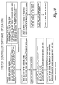
- Fig. 10 is a self-explanatory flowchart of the software associated with the system controller's microcontroller 110.
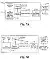
- Fig. 7A is a schematic block diagram of a balance control circuit 138 of an emitter module 24 1 .
- An ion balance sensor 140 (which includes an op-amp plus an A/D converter) outputs a balance measurement, B MEAS , taken relatively close to the emitters of the emitter module 24 1 .
- the balance reference value 142 stored in the microcontroller 44, B REF1 is compared to B MEAS in comparator 144. If the values are equal, no adjustment is made to the positive or negative high voltage power supplies 146 . If the values are not equal, appropriate adjustments are made to the power supplies 146 until the values become equal. This process occurs continuously and automatically during operation of the emitter module 24 1 .
- B REF1 is adjusted up or down by using either the remote control transmitter 30 or the system controller 28 until B ACTUAL is brought back to zero. Due to manufacturing tolerances and system degradation over time, each emitter module 24 will thus likely have a different B REF value.
- Fig. 7B is a scheme similar to Fig. 7A which is used for the ion current, as discussed above with respect to C REF and C MEAS .
- C MEAS is the actual ion output current, as directly measured using the circuit elements 56, 58 and 60 shown in Fig. 4.
- Comparator 152 compares C REF1 (which is stored in memory 150 in the microcontroller 44 ) with C MEAS . If the values are equal, no adjustment is made to the positive or negative high voltage power supplies 146. If the values are not equal, appropriate adjustments are made to the power supplies 146 until the values become equal. This process occurs continuously and automatically during operation of the emitter module 24 1 .
- decay time readings are taken from a charged plate monitor 148 to obtain an indication of the actual ion output current, C MEAS , in the work space near the emitter module 24 1 . If the decay time is within a desired range, then no further action is taken. However, if the decay time is too slow or too fast, C REF1 is adjusted upward or downward by the operator. The comparator 152 will then show a difference between C MEAS and C REF1 , and appropriate adjustments are automatically made to the power supplies 146 until these values become equal in the same manner as described above.
- Fig. 8 shows a perspective view of the hardware components of the system 22 of Fig. 2.
- microcontrollers 44 and 110 allow sophisticated features to be implemented, such as the following features:
- the communications need not necessarily be via RS-485 or RS-232 communication/power lines.
- the miswire protection circuitry may be used with any type of communication/power lines that can be flipped via switches in the manner described above.
Landscapes
- Elimination Of Static Electricity (AREA)
- Selective Calling Equipment (AREA)
Applications Claiming Priority (3)
| Application Number | Priority Date | Filing Date | Title |
|---|---|---|---|
| US10101898P | 1998-09-18 | 1998-09-18 | |
| US101018P | 1998-09-18 | ||
| EP19990115192 EP0987929B1 (de) | 1998-09-18 | 1999-08-16 | Ionisierungssystem |
Related Parent Applications (2)
| Application Number | Title | Priority Date | Filing Date |
|---|---|---|---|
| EP99115192.9 Division | 1999-08-16 | ||
| EP19990115192 Division EP0987929B1 (de) | 1998-09-18 | 1999-08-16 | Ionisierungssystem |
Publications (3)
| Publication Number | Publication Date |
|---|---|
| EP1508948A2 true EP1508948A2 (de) | 2005-02-23 |
| EP1508948A3 EP1508948A3 (de) | 2012-03-21 |
| EP1508948B1 EP1508948B1 (de) | 2014-03-05 |
Family
ID=34066540
Family Applications (1)
| Application Number | Title | Priority Date | Filing Date |
|---|---|---|---|
| EP04022890.0A Expired - Lifetime EP1508948B1 (de) | 1998-09-18 | 1999-08-16 | Modulares Niederspannungs-Raumionisierungssystem |
Country Status (1)
| Country | Link |
|---|---|
| EP (1) | EP1508948B1 (de) |
Cited By (2)
| Publication number | Priority date | Publication date | Assignee | Title |
|---|---|---|---|---|
| DE102008049279A1 (de) * | 2008-09-26 | 2010-04-01 | Behr Gmbh & Co. Kg | Ionisationsvorrichtung |
| WO2018098421A1 (en) * | 2016-11-28 | 2018-05-31 | Illinois Tool Works Inc. | Control system of a balanced micro-pulsed ionizer blower |
Citations (7)
| Publication number | Priority date | Publication date | Assignee | Title |
|---|---|---|---|---|
| JPS63143954A (ja) | 1986-12-03 | 1988-06-16 | ボイエイジヤ−.テクノロジ−ズ | 空気イオン化方法及び装置 |
| US4757422A (en) | 1986-09-15 | 1988-07-12 | Voyager Technologies, Inc. | Dynamically balanced ionization blower |
| US4757421A (en) | 1987-05-29 | 1988-07-12 | Honeywell Inc. | System for neutralizing electrostatically-charged objects using room air ionization |
| US4809127A (en) | 1987-08-11 | 1989-02-28 | Ion Systems, Inc. | Self-regulating air ionizing apparatus |
| US4901194A (en) | 1988-07-20 | 1990-02-13 | Ion Systems, Inc. | Method and apparatus for regulating air ionization |
| US4974115A (en) | 1988-11-01 | 1990-11-27 | Semtronics Corporation | Ionization system |
| JPH04308694A (ja) | 1991-04-08 | 1992-10-30 | Kitagawa Ind Co Ltd | 帯電防止用イオン発生装置 |
Family Cites Families (1)
| Publication number | Priority date | Publication date | Assignee | Title |
|---|---|---|---|---|
| US4630167A (en) * | 1985-03-11 | 1986-12-16 | Cybergen Systems, Inc. | Static charge neutralizing system and method |
-
1999
- 1999-08-16 EP EP04022890.0A patent/EP1508948B1/de not_active Expired - Lifetime
Patent Citations (7)
| Publication number | Priority date | Publication date | Assignee | Title |
|---|---|---|---|---|
| US4757422A (en) | 1986-09-15 | 1988-07-12 | Voyager Technologies, Inc. | Dynamically balanced ionization blower |
| JPS63143954A (ja) | 1986-12-03 | 1988-06-16 | ボイエイジヤ−.テクノロジ−ズ | 空気イオン化方法及び装置 |
| US4757421A (en) | 1987-05-29 | 1988-07-12 | Honeywell Inc. | System for neutralizing electrostatically-charged objects using room air ionization |
| US4809127A (en) | 1987-08-11 | 1989-02-28 | Ion Systems, Inc. | Self-regulating air ionizing apparatus |
| US4901194A (en) | 1988-07-20 | 1990-02-13 | Ion Systems, Inc. | Method and apparatus for regulating air ionization |
| US4974115A (en) | 1988-11-01 | 1990-11-27 | Semtronics Corporation | Ionization system |
| JPH04308694A (ja) | 1991-04-08 | 1992-10-30 | Kitagawa Ind Co Ltd | 帯電防止用イオン発生装置 |
Cited By (2)
| Publication number | Priority date | Publication date | Assignee | Title |
|---|---|---|---|---|
| DE102008049279A1 (de) * | 2008-09-26 | 2010-04-01 | Behr Gmbh & Co. Kg | Ionisationsvorrichtung |
| WO2018098421A1 (en) * | 2016-11-28 | 2018-05-31 | Illinois Tool Works Inc. | Control system of a balanced micro-pulsed ionizer blower |
Also Published As
| Publication number | Publication date |
|---|---|
| EP1508948A3 (de) | 2012-03-21 |
| EP1508948B1 (de) | 2014-03-05 |
Similar Documents
| Publication | Publication Date | Title |
|---|---|---|
| US6252756B1 (en) | Low voltage modular room ionization system | |
| EP1067828B1 (de) | Sorfortiges Balancesteuerungsablauf für einen Ionisator | |
| EP1508948B1 (de) | Modulares Niederspannungs-Raumionisierungssystem | |
| US9356434B2 (en) | Active ionization control with closed loop feedback and interleaved sampling |
Legal Events
| Date | Code | Title | Description |
|---|---|---|---|
| PUAI | Public reference made under article 153(3) epc to a published international application that has entered the european phase |
Free format text: ORIGINAL CODE: 0009012 |
|
| 17P | Request for examination filed |
Effective date: 20040925 |
|
| AC | Divisional application: reference to earlier application |
Ref document number: 0987929 Country of ref document: EP Kind code of ref document: P |
|
| AK | Designated contracting states |
Kind code of ref document: A2 Designated state(s): AT BE CH CY DE DK ES FI FR GB GR IE IT LI LU MC NL PT SE |
|
| RIN1 | Information on inventor provided before grant (corrected) |
Inventor name: RODRIGO, RICHARD D. Inventor name: RICHIE, WILLIAM S., JR. Inventor name: HALL, PHILIP R. |
|
| REG | Reference to a national code |
Ref country code: DE Ref legal event code: R079 Ref document number: 69945018 Country of ref document: DE Free format text: PREVIOUS MAIN CLASS: H01T0023000000 Ipc: H05F0003040000 |
|
| PUAL | Search report despatched |
Free format text: ORIGINAL CODE: 0009013 |
|
| AK | Designated contracting states |
Kind code of ref document: A3 Designated state(s): AT BE CH CY DE DK ES FI FR GB GR IE IT LI LU MC NL PT SE |
|
| RIC1 | Information provided on ipc code assigned before grant |
Ipc: H01T 23/00 20060101ALI20120213BHEP Ipc: H05F 3/04 20060101AFI20120213BHEP |
|
| 17Q | First examination report despatched |
Effective date: 20120911 |
|
| AKX | Designation fees paid |
Designated state(s): AT BE CH CY DE DK ES FI FR GB GR IE IT LI LU MC NL PT SE |
|
| TPAC | Observations by third parties |
Free format text: ORIGINAL CODE: EPIDOSNTIPA |
|
| GRAP | Despatch of communication of intention to grant a patent |
Free format text: ORIGINAL CODE: EPIDOSNIGR1 |
|
| INTG | Intention to grant announced |
Effective date: 20131106 |
|
| GRAS | Grant fee paid |
Free format text: ORIGINAL CODE: EPIDOSNIGR3 |
|
| GRAA | (expected) grant |
Free format text: ORIGINAL CODE: 0009210 |
|
| AC | Divisional application: reference to earlier application |
Ref document number: 0987929 Country of ref document: EP Kind code of ref document: P |
|
| AK | Designated contracting states |
Kind code of ref document: B1 Designated state(s): AT BE CH CY DE DK ES FI FR GB GR IE IT LI LU MC NL PT SE |
|
| REG | Reference to a national code |
Ref country code: GB Ref legal event code: FG4D |
|
| REG | Reference to a national code |
Ref country code: CH Ref legal event code: EP |
|
| REG | Reference to a national code |
Ref country code: AT Ref legal event code: REF Ref document number: 655599 Country of ref document: AT Kind code of ref document: T Effective date: 20140315 |
|
| REG | Reference to a national code |
Ref country code: IE Ref legal event code: FG4D |
|
| RAP2 | Party data changed (patent owner data changed or rights of a patent transferred) |
Owner name: ILLINOIS TOOL WORKS INC. |
|
| REG | Reference to a national code |
Ref country code: DE Ref legal event code: R096 Ref document number: 69945018 Country of ref document: DE Effective date: 20140417 |
|
| REG | Reference to a national code |
Ref country code: AT Ref legal event code: MK05 Ref document number: 655599 Country of ref document: AT Kind code of ref document: T Effective date: 20140305 |
|
| REG | Reference to a national code |
Ref country code: NL Ref legal event code: VDEP Effective date: 20140305 |
|
| PG25 | Lapsed in a contracting state [announced via postgrant information from national office to epo] |
Ref country code: CY Free format text: LAPSE BECAUSE OF FAILURE TO SUBMIT A TRANSLATION OF THE DESCRIPTION OR TO PAY THE FEE WITHIN THE PRESCRIBED TIME-LIMIT Effective date: 20140305 Ref country code: SE Free format text: LAPSE BECAUSE OF FAILURE TO SUBMIT A TRANSLATION OF THE DESCRIPTION OR TO PAY THE FEE WITHIN THE PRESCRIBED TIME-LIMIT Effective date: 20140305 Ref country code: FI Free format text: LAPSE BECAUSE OF FAILURE TO SUBMIT A TRANSLATION OF THE DESCRIPTION OR TO PAY THE FEE WITHIN THE PRESCRIBED TIME-LIMIT Effective date: 20140305 Ref country code: AT Free format text: LAPSE BECAUSE OF FAILURE TO SUBMIT A TRANSLATION OF THE DESCRIPTION OR TO PAY THE FEE WITHIN THE PRESCRIBED TIME-LIMIT Effective date: 20140305 |
|
| PG25 | Lapsed in a contracting state [announced via postgrant information from national office to epo] |
Ref country code: BE Free format text: LAPSE BECAUSE OF FAILURE TO SUBMIT A TRANSLATION OF THE DESCRIPTION OR TO PAY THE FEE WITHIN THE PRESCRIBED TIME-LIMIT Effective date: 20140305 Ref country code: NL Free format text: LAPSE BECAUSE OF FAILURE TO SUBMIT A TRANSLATION OF THE DESCRIPTION OR TO PAY THE FEE WITHIN THE PRESCRIBED TIME-LIMIT Effective date: 20140305 |
|
| PG25 | Lapsed in a contracting state [announced via postgrant information from national office to epo] |
Ref country code: ES Free format text: LAPSE BECAUSE OF FAILURE TO SUBMIT A TRANSLATION OF THE DESCRIPTION OR TO PAY THE FEE WITHIN THE PRESCRIBED TIME-LIMIT Effective date: 20140305 |
|
| REG | Reference to a national code |
Ref country code: DE Ref legal event code: R097 Ref document number: 69945018 Country of ref document: DE |
|
| PG25 | Lapsed in a contracting state [announced via postgrant information from national office to epo] |
Ref country code: PT Free format text: LAPSE BECAUSE OF FAILURE TO SUBMIT A TRANSLATION OF THE DESCRIPTION OR TO PAY THE FEE WITHIN THE PRESCRIBED TIME-LIMIT Effective date: 20140707 |
|
| PLBE | No opposition filed within time limit |
Free format text: ORIGINAL CODE: 0009261 |
|
| STAA | Information on the status of an ep patent application or granted ep patent |
Free format text: STATUS: NO OPPOSITION FILED WITHIN TIME LIMIT |
|
| PG25 | Lapsed in a contracting state [announced via postgrant information from national office to epo] |
Ref country code: DK Free format text: LAPSE BECAUSE OF FAILURE TO SUBMIT A TRANSLATION OF THE DESCRIPTION OR TO PAY THE FEE WITHIN THE PRESCRIBED TIME-LIMIT Effective date: 20140305 |
|
| 26N | No opposition filed |
Effective date: 20141208 |
|
| REG | Reference to a national code |
Ref country code: DE Ref legal event code: R097 Ref document number: 69945018 Country of ref document: DE Effective date: 20141208 |
|
| PG25 | Lapsed in a contracting state [announced via postgrant information from national office to epo] |
Ref country code: LU Free format text: LAPSE BECAUSE OF FAILURE TO SUBMIT A TRANSLATION OF THE DESCRIPTION OR TO PAY THE FEE WITHIN THE PRESCRIBED TIME-LIMIT Effective date: 20140816 Ref country code: MC Free format text: LAPSE BECAUSE OF FAILURE TO SUBMIT A TRANSLATION OF THE DESCRIPTION OR TO PAY THE FEE WITHIN THE PRESCRIBED TIME-LIMIT Effective date: 20140305 |
|
| REG | Reference to a national code |
Ref country code: CH Ref legal event code: PL |
|
| GBPC | Gb: european patent ceased through non-payment of renewal fee |
Effective date: 20140816 |
|
| PG25 | Lapsed in a contracting state [announced via postgrant information from national office to epo] |
Ref country code: CH Free format text: LAPSE BECAUSE OF NON-PAYMENT OF DUE FEES Effective date: 20140831 Ref country code: LI Free format text: LAPSE BECAUSE OF NON-PAYMENT OF DUE FEES Effective date: 20140831 |
|
| PG25 | Lapsed in a contracting state [announced via postgrant information from national office to epo] |
Ref country code: GB Free format text: LAPSE BECAUSE OF NON-PAYMENT OF DUE FEES Effective date: 20140816 |
|
| REG | Reference to a national code |
Ref country code: FR Ref legal event code: PLFP Year of fee payment: 17 |
|
| PG25 | Lapsed in a contracting state [announced via postgrant information from national office to epo] |
Ref country code: GR Free format text: LAPSE BECAUSE OF FAILURE TO SUBMIT A TRANSLATION OF THE DESCRIPTION OR TO PAY THE FEE WITHIN THE PRESCRIBED TIME-LIMIT Effective date: 20140606 |
|
| REG | Reference to a national code |
Ref country code: FR Ref legal event code: PLFP Year of fee payment: 18 |
|
| REG | Reference to a national code |
Ref country code: FR Ref legal event code: PLFP Year of fee payment: 19 |
|
| REG | Reference to a national code |
Ref country code: FR Ref legal event code: PLFP Year of fee payment: 20 |
|
| PGFP | Annual fee paid to national office [announced via postgrant information from national office to epo] |
Ref country code: DE Payment date: 20180829 Year of fee payment: 20 Ref country code: IT Payment date: 20180822 Year of fee payment: 20 Ref country code: FR Payment date: 20180827 Year of fee payment: 20 Ref country code: IE Payment date: 20180827 Year of fee payment: 20 |
|
| REG | Reference to a national code |
Ref country code: DE Ref legal event code: R071 Ref document number: 69945018 Country of ref document: DE |
|
| REG | Reference to a national code |
Ref country code: IE Ref legal event code: MK9A |
|
| PG25 | Lapsed in a contracting state [announced via postgrant information from national office to epo] |
Ref country code: IE Free format text: LAPSE BECAUSE OF EXPIRATION OF PROTECTION Effective date: 20190816 |