EP1508976A1 - Modem DSL et méthode de contrôle de communication - Google Patents
Modem DSL et méthode de contrôle de communication Download PDFInfo
- Publication number
- EP1508976A1 EP1508976A1 EP04012340A EP04012340A EP1508976A1 EP 1508976 A1 EP1508976 A1 EP 1508976A1 EP 04012340 A EP04012340 A EP 04012340A EP 04012340 A EP04012340 A EP 04012340A EP 1508976 A1 EP1508976 A1 EP 1508976A1
- Authority
- EP
- European Patent Office
- Prior art keywords
- signal
- echo
- transmission
- atu
- communication
- Prior art date
- Legal status (The legal status is an assumption and is not a legal conclusion. Google has not performed a legal analysis and makes no representation as to the accuracy of the status listed.)
- Granted
Links
Images


Classifications
-
- H—ELECTRICITY
- H04—ELECTRIC COMMUNICATION TECHNIQUE
- H04L—TRANSMISSION OF DIGITAL INFORMATION, e.g. TELEGRAPHIC COMMUNICATION
- H04L27/00—Modulated-carrier systems
- H04L27/01—Equalisers
-
- H—ELECTRICITY
- H04—ELECTRIC COMMUNICATION TECHNIQUE
- H04L—TRANSMISSION OF DIGITAL INFORMATION, e.g. TELEGRAPHIC COMMUNICATION
- H04L5/00—Arrangements affording multiple use of the transmission path
- H04L5/14—Two-way operation using the same type of signal, i.e. duplex
- H04L5/143—Two-way operation using the same type of signal, i.e. duplex for modulated signals
-
- H—ELECTRICITY
- H04—ELECTRIC COMMUNICATION TECHNIQUE
- H04B—TRANSMISSION
- H04B3/00—Line transmission systems
- H04B3/02—Details
- H04B3/20—Reducing echo effects or singing; Opening or closing transmitting path; Conditioning for transmission in one direction or the other
- H04B3/23—Reducing echo effects or singing; Opening or closing transmitting path; Conditioning for transmission in one direction or the other using a replica of transmitted signal in the time domain, e.g. echo cancellers
-
- H—ELECTRICITY
- H04—ELECTRIC COMMUNICATION TECHNIQUE
- H04M—TELEPHONIC COMMUNICATION
- H04M11/00—Telephonic communication systems specially adapted for combination with other electrical systems
- H04M11/06—Simultaneous speech and data transmission, e.g. telegraphic transmission over the same conductors
- H04M11/062—Simultaneous speech and data transmission, e.g. telegraphic transmission over the same conductors using different frequency bands for speech and other data
-
- H—ELECTRICITY
- H04—ELECTRIC COMMUNICATION TECHNIQUE
- H04L—TRANSMISSION OF DIGITAL INFORMATION, e.g. TELEGRAPHIC COMMUNICATION
- H04L5/00—Arrangements affording multiple use of the transmission path
- H04L5/02—Channels characterised by the type of signal
- H04L5/023—Multiplexing of multicarrier modulation signals, e.g. multi-user orthogonal frequency division multiple access [OFDMA]
Definitions
- the present invention relates to a DSL modem apparatus and communication control method that can be applied to digital communication using a metallic cable.
- An ADSL method one type of xDSL realizing the high-speed communication, employs a DMT (discrete multi tone) modulation method using a plurality of carriers (sub-carriers) in a wide frequency band.
- DMT discrete multi tone modulation method using a plurality of carriers (sub-carriers) in a wide frequency band.
- G.992.1 which is one of the ADSL standards, divides the frequency band ranging from 25kHz to 1.1MHz into 256 carriers (sub-carriers). Index number (#) is assigned to each sub-carrier, numbering from the low frequency carrier.
- sub-carriers #32 - #255 are generally used for a downstream, i.e., transmission from a center side (exchange side, ATU-C) to a remote side (user side, ATU-R).
- ATU-C exchange side
- ATU-R remote side
- sub-carriers #7 - #31 are used for upstream transmission from ATU-R to ATU-C.
- sub-carriers #7- #255 can be used in the downstream communication as shown in Fig. 7 (b).
- both ATU-C and ATU-R use sub-carriers #7-#31.
- ATU-R uses an echo canceller in order to prevent an echo from its own transmission signal.
- an echo canceller it is necessary to learn about the echo from its own apparatus in advance (e.g., Related Art 1).
- AT-C transmits sub-carriers #7 - #255, as shown in Fig. 8 (a), in order to detect the echo of each sub-carrier #7 - #255. Transmission from ATU-R during such time would cause interference in sub-carriers #7 - #31, therefore, the transmission from ATU-R is stopped.
- sub-carriers of #7 - #31 are transmitted as shown in Fig. 8 (b) in order to detect the echo of each sub-carrier #7 - #31.
- Transmission of ATU-C is stopped except for sub-carrier #64, which is used by ATU-C for the transmission of a PILOT signal. Since the ATU-R synchronizes with the ATU-C based on the PILOT signal transmitted by ATU-C, the PILOT signal transmission should not be stopped.
- the sub-carrier used for the PILOT signal transmission is #64, which is largely distant from the sub-carriers used by ATU-R, thereby the PILOT signal does not interfere with the echo canceller learning.
- an opposing apparatus transmits signals that can interfere with transmission signals from its own apparatus (not limited to PILOT signal of #64), during an echo canceller learning period at ATU-R or ATU-C, it becomes difficult to perform the complete echo canceller learning, thereby creating an adverse effect to the succeeding data communication.
- the present invention addresses the above-described problems.
- the purpose of the invention is to provide a DSL modem apparatus and a communication control method that allows a highly accurate echo canceller learning, even when the upstream frequency band used by ATU-R includes PILOT signals transmitted by ATU-C, and enables the downstream communication to utilize the wide range of frequency band, similar to the downstream.
- This invention controls the data transmission to be stopped for carrier-indexes for a specific signal, the signal being transmitted by the opposing communication apparatus. Further, a notch unit is provided at a frequency location of the specific signal so that the transmission signal from its own apparatus is cut at the frequency location of the specific signal and at the reception side.
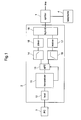
- Fig. 1 illustrates a schematic configuration of a communication system of an ATU-R side, according to the present invention.
- a public phone line or a similar phone line hereafter referred to as line
- ADSL modem apparatus 2 is connected to ADSL modem apparatus 2.
- user terminal 3 is connected to ADSL modem apparatus 2.
- splitter 1 is necessary.
- splitter 1 is not needed. It is also possible to have a configuration where user terminal 3 internally installs ADSL modem apparatus 2.
- ADSL modem apparatus 2 includes transceiver 11 that executes ADSL communication, and host 12 that controls the entire operation including the one of transceiver 11.
- transceiver 11 that executes ADSL communication
- host 12 that controls the entire operation including the one of transceiver 11.
- units are configured with an analog circuit via analog front end (hereafter referred to as AFE) 13.
- AFE analog front end
- Driver 15 is connected to a DA converter 13-1 of AFE 13 via analog notch filter 14, so that an analog signal amplified by driver 15 is transmitted to the line via hybrid 16.
- the analog signal transmitted from the line is received by receiver 17 via hybrid 16, and then input into an AD converter of AFE 13 via analog filter 18.
- AFE 13 When sampling data is output from the AD converter, AFE 13 outputs the data to transceiver 11.
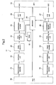
- Fig. 2 is a functional block diagram illustrating transceiver 11.
- Processor 20 has functions to execute handshake and initialization sequences and to control communication during data transmission (SHOWTIME).
- the transmission side of transceiver 11 includes Reed-Solomon encoder 21 that adds a redundancy bit for checking error, interleave unit 22 that sorts data to enable a burst error correction during Reed-Solomon decoding, trellis encoder 23 that performs data convolution from a trellis encoding, tone ordering unit 24 that lays out a bit number for each carrier, constellation encoder 25 that allocates topology of the transmission data on constellation coordinates, and IFFT unit 26 that performs an Inverse Fast Fourier Transform (hereafter referred to as IFFT) on data after the constellation encoding process.
- IFFT Inverse Fast Fourier Transform
- the reception process side of transceiver 11 includes FFT unit 27 that performs a Fast Fourier Transform (hereafter referred to as FFT) on sampling data of the received signal, constellation decoder/FEQ unit 28 that decodes data from constellation data of the FFT output signal and corrects a topology on the constellation coordinates, tone deordering unit 29 that restores data assigned to each carrier after tone ordering process at the transmission side, Viterbi decoder 30 that performs Viterbi decoding on the received data, de-interleave unit 31 that restores data being resorted by the transmission side, and Reed-Solomon decoder 32 that deletes the redundancy bit added by the transmission side.
- RAM 33 is a work area of processor 20, which will be used for executing handshake and initialization sequences.
- Transceiver 11 is connected to host 12 via host interface (I/F) 34.
- I/F host interface
- FIG. 3 is a block diagram illustrating the internal structure of AFE 13.
- AFE 13 is provided with an echo canceller function and a digital filter function.
- Digital notch filter 41 is connected to the input section of DAC 13-1.
- Digital notch filter 41 has a function to remove signal energy of sub-carrier #64 area that is used by ATU-C for a PILOT signal.
- ATU-R transmits signals using sub-carrier in a wide frequency band (e.g., #7 - #255) while no energy is applied to sub-carrier #64 (frequency location of the PILOT signal). At the frequency location of #64, transmission data having no signal energy is converted into an analog signal.
- analog notch filter 14 removes signal energy at the frequency location of sub-carrier #64.
- This signal energy is affected by signals from the adjacent sub-carriers #63 and #65.
- signal energy at each frequency location is diffused into adjacent frequency locations due to the skirt shape of its energy. Therefore, the signal energy at the frequency location of sub-carrier #64 is also affected by signal energy diffused from adjacent frequency locations.
- analog notch filter 18 located at the output section of receiver 17
- digital notch filter 42 located at the output section of ADC 13-2
- a notch unit includes digital notch filter 41, analog notch filter 14, analog notch filter 18, and digital notch filter 42.
- the transmission signal output from IFFT unit 26 is diverged and captured by echo canceller 43.
- the transmission signal from ATU-C via receiver 17, analog notch filter 18, and ADC 13-2
- echo component of its own transmission signal via IFFT unit 26, digital notch filter 41, DAC 13-1, analog notch filter 14, driver 15, receiver 17, analog notch filter 18, and ADC 13-2
- ATU-R echo component of its own transmission signal
- the input section of FFT unit 27 is provided with subtracter 44, where the transmission signal of echo canceller 43 is subtracted from the output signal of digital notch filter 42.
- the result of the subtraction is input to FFT unit 27, as a reception signal.
- An ADSL modem apparatus of the center side is connected to ADSL modem apparatus 2 via a metallic cable.
- the ADSL modem apparatus of the center side has the same configuration as ADSL modem apparatus 2.
- telephone 4 does not exist.
- echo canceller 43 performs an echo canceller learning in order to remove the echo signal.
- ATU-R When ATU-R is turned on, the process illustrated in Fig. 5 is performed. First, ATU-C and ATU-R perform the handshake sequence based on G.944.1 and select a mode. Using the example shown in Fig. 5, G.dmt is selected as a mode for the initialization sequence.
- ATU-C transmits C-PILOT1 or C-PILOT1A signal using indexes #64 and #48.
- ATU-R When the initialization sequence is initiated, and when ATU-R detects signal energy at indexes #64 and #48, ATU-R starts a hyperframe synchronization process based on the PILOT signal. After establishing the hyperframe, ATU-R transmits a R-REVERB1 signal.
- ATU-C Upon detecting the R-REVERB1 signal, ATU-C transmits a C-REVERB1 signal to the remote side.
- ATU-C Upon detecting the R-REVERB1 signal, ATU-C sequentially transmits C-REVERB 1, C-PILOT2, C-ECT, and C-REVERB2 for a predetermined number of symbols.
- ATU-R Based on the C-REVERB or C-REVERB2, ATU-R performs the symbol synchronization.
- ATU-C Upon transmitting C-REVERB3, ATU-C transmits C-SEGUE1, while, upon transmitting R-REVERB2, ATU-R transmits R-SEGUE1 for a plurality of symbols. Thereafter, cyclic prefix data is added to each symbol, since important signals are exchanged that determine parameters during the SHOWTIME.
- a RATES signal and an MSG signal with cyclic prefix data are transmitted in order to determine various communication parameters by exchanging communication speed, encoding parameter, and tone-ordering information. Although the following sequence is omitted, both sides confirm the determination of the communication parameters and perform data communication (SHOWTIME).
- ATU-R performs the echo canceller learning. As shown in Fig. 5, when ATU-R is in the period of R-ECT, ATU-C stops the transmission of C-REVERB2 signal and transmits C-PILOT3 using sub-carrier #64.
- ATU-R performs the echo canceller learning (by echo canceller 43) for the all sub-carriers used during the SHOWTIME.
- the upstream uses the same sub-carriers #7 - #255 as the downstream. Therefore, processor 20 generates a training signal (transmission data) carried by sub-carriers #7 - #255, and inputs the training signal into IFFT unit 26. However, transmission data to be carried by sub-carrier #64 (frequency location of the PILOT signal) is not generated.
- IFFT unit 26 outputs a digital modulation signal (training signal) to digital notch filter 41.
- the signal is modulated so that transmission data is loaded to each sub-carrier #7- #255 (excluding #64). Since digital notch filter 41 has the filter characteristics as described earlier, signal energy components at the frequency location of #64 are removed from the input signal. Accordingly, a training signal, where the signal energy components at the frequency location of #64 are removed, is generated for #7 - #255 (excluding #64).
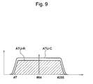
- analog notch filter 14 filters the signal into a waveform. Especially, due to the frequency characteristics of analog notch filter 14, the signal energy at the frequency location of #64 is removed. Therefore, the training signal having a carrier hole at the frequency location of #64 as shown in Fig. 4.
- the training signal being configured with sub-carriers #7 - #255 and having a carrier hole at frequency location #64 is transmitted to the line via driver 15.
- Receiver 17 receives an echo signal of the training signal.
- the echo signal is given a waveform by analog notch filter 18, and is converted into a digital echo signal at ADC 13-2.
- the digital echo signal is input to subtracter 44 via digital notch filter 42.
- Subtracter 44 is also provided with transmission data (training signal) of #7-#255, the data being transmitted from its own apparatus via echo canceller 43.
- the difference between the transmission data of its own apparatus and the echo signal is detected, in order to find a most suitable coefficient that can convert transmission data into the echo signal.
- the above process is referred to as an echo canceller learning.
- Receiver 17 cannot find a most suitable coefficient when the transmission signal from the ATU-C interferes with the echo signal originated from its own transmission signal (training signal). Therefore, ATU-C does not transmit signals other than PILOT signals, which is minimally required.
- the transmission signal from ATU-R has a carrier hole in the frequency location of the PILOT signal (#64), thereby preventing the interference of the PILOT signal with the echo signal.
- the echo signal configured with frequencies excluding the frequency of #64 is configured purely with the echo signal of its own transmission signal.
- a most suitable coefficient for converting the transmission data into an echo signal is found, from an echo signal that does not have any interference of the PILOT signal. Then, the coefficient is set in echo canceller 43. Although the transmission data of #64 is subtracted from the PILOT signal, the transmission data at the frequency location #64 has no data. Therefore, the PILOT signal is directly provided to processor 20 via pilot tone receiving circuit 45, and is used by processor 20 for its synchronization.
- ATU-C side performs a training of echo canceller 43 during the C-ECT period.
- ATU-R stops the transmission of R-REVERB signal during the C-ECT period and has a silence (R-QUIET3). Therefore, as shown in Fig. 6, ATU-C can detect the echo signal without the interference with the remote side signal, even though ATU-C transmits the training signal throughout the transmission band (#7-#255). Similar to the remote side, a most suitable coefficient is calculated from the difference between the echo signal and the transmission signal.
- the upstream communication (transmission from ATU-R to ATU-C) is performed in a multi-carrier method, using carriers of carrier indexes #7 - #255 and having a carrier hole at the location of the PILOT signal, as shown in Fig. 4. Further, the downstream communication (transmission from ATU-C to ATU-R) is performed using all carriers of #7 - #255 as shown in Fig. 6. However, #64 (in the downstream communication) is used for the PILOT signal.
- sub-carrier #64 always has no transmission data from the ATU-R (upstream), so that there is a carrier hole in the frequency location of #64.
- ATU-C transmits the PILOT signal using sub-carrier #64, and transmits the transmission data using other sub-carriers. Accordingly, the echo canceller learning can be accurately performed using the entire frequency band.
- the upstream communication can be performed after the echo canceller learning, using the same carrier indexes (except #64) as the downstream, thereby improving the upstream speed.
- a notch filter is provided at the frequency location of the PILOT signal, the signal being transmitted from the center side.
- a notch filter can be provided at the frequency location of the specific signal in order to perform the echo canceller learning without the echo interference of the specific signal.
- a notch filter can be provided at the frequency location of the specific signal (similar to the above) in order to perform the echo canceller learning without the echo interference of the specific signal.
- ADSL modem for the example
- present invention can be applied to other xDSL modems.
Landscapes
- Engineering & Computer Science (AREA)
- Signal Processing (AREA)
- Computer Networks & Wireless Communication (AREA)
- Telephonic Communication Services (AREA)
- Cable Transmission Systems, Equalization Of Radio And Reduction Of Echo (AREA)
Applications Claiming Priority (2)
| Application Number | Priority Date | Filing Date | Title |
|---|---|---|---|
| JP2003299109A JP2005072898A (ja) | 2003-08-22 | 2003-08-22 | Dslモデム装置及び通信制御方法 |
| JP2003299109 | 2003-08-22 |
Publications (2)
| Publication Number | Publication Date |
|---|---|
| EP1508976A1 true EP1508976A1 (fr) | 2005-02-23 |
| EP1508976B1 EP1508976B1 (fr) | 2008-05-28 |
Family
ID=34056273
Family Applications (1)
| Application Number | Title | Priority Date | Filing Date |
|---|---|---|---|
| EP04012340A Expired - Lifetime EP1508976B1 (fr) | 2003-08-22 | 2004-05-25 | Modem DSL et méthode de contrôle de communication |
Country Status (5)
| Country | Link |
|---|---|
| US (1) | US20050041729A1 (fr) |
| EP (1) | EP1508976B1 (fr) |
| JP (1) | JP2005072898A (fr) |
| KR (1) | KR20050020579A (fr) |
| DE (1) | DE602004014076D1 (fr) |
Families Citing this family (2)
| Publication number | Priority date | Publication date | Assignee | Title |
|---|---|---|---|---|
| JP4861796B2 (ja) * | 2006-11-15 | 2012-01-25 | ルネサスエレクトロニクス株式会社 | 無線通信装置及び通信処理回路 |
| WO2019114961A1 (fr) * | 2017-12-13 | 2019-06-20 | Telefonaktiebolaget Lm Ericsson (Publ) | Procédé d'estimation d'une différence de retard de propagation d'une liaison optique et appareil associé |
Citations (2)
| Publication number | Priority date | Publication date | Assignee | Title |
|---|---|---|---|---|
| EP0766412A2 (fr) * | 1995-09-29 | 1997-04-02 | Paradyne Corporation | Annulateur d'écho utilisant un entraînement initial |
| US20030108094A1 (en) * | 2001-12-10 | 2003-06-12 | Yhean-Sen Lai | Modem with enhanced echo canceler |
Family Cites Families (3)
| Publication number | Priority date | Publication date | Assignee | Title |
|---|---|---|---|---|
| AU695092B2 (en) * | 1994-06-02 | 1998-08-06 | Amati Communications Corporation | Method and apparatus for coordinating multi-point-to-point communications in a multi-tone data transmission system |
| US6980560B2 (en) * | 2001-05-25 | 2005-12-27 | Mindspeed Technologies, Inc. | System and method for connecting communication devices over packet networks |
| JP2004072269A (ja) * | 2002-08-02 | 2004-03-04 | Panasonic Communications Co Ltd | Adslモデム装置及びその通信方法 |
-
2003
- 2003-08-22 JP JP2003299109A patent/JP2005072898A/ja active Pending
-
2004
- 2004-02-20 US US10/781,678 patent/US20050041729A1/en not_active Abandoned
- 2004-04-30 KR KR1020040030659A patent/KR20050020579A/ko not_active Ceased
- 2004-05-25 EP EP04012340A patent/EP1508976B1/fr not_active Expired - Lifetime
- 2004-05-25 DE DE602004014076T patent/DE602004014076D1/de not_active Expired - Fee Related
Patent Citations (2)
| Publication number | Priority date | Publication date | Assignee | Title |
|---|---|---|---|---|
| EP0766412A2 (fr) * | 1995-09-29 | 1997-04-02 | Paradyne Corporation | Annulateur d'écho utilisant un entraînement initial |
| US20030108094A1 (en) * | 2001-12-10 | 2003-06-12 | Yhean-Sen Lai | Modem with enhanced echo canceler |
Also Published As
| Publication number | Publication date |
|---|---|
| DE602004014076D1 (de) | 2008-07-10 |
| EP1508976B1 (fr) | 2008-05-28 |
| KR20050020579A (ko) | 2005-03-04 |
| US20050041729A1 (en) | 2005-02-24 |
| JP2005072898A (ja) | 2005-03-17 |
Similar Documents
| Publication | Publication Date | Title |
|---|---|---|
| CA2266372C (fr) | Systeme de transmission numerique de donnees, procede et dispositifs appropries | |
| US7010027B1 (en) | Multistandard discrete multi-tone (DMT) digital subscriber line (DSL) system | |
| EP1610515A1 (fr) | Procédé et système de temporisation des synchronisations dans un système à plusieurs porteuses | |
| US6690666B1 (en) | Packet modulation for DSL | |
| US7305001B2 (en) | ADSL modem apparatus and ADSL modem communication method | |
| EP1508976A1 (fr) | Modem DSL et méthode de contrôle de communication | |
| EP1507397A2 (fr) | Dispositif de modem DSL et procédé de commande de communication | |
| EP1367809B1 (fr) | Initialisation DSL, par utilisation de la mémoire entrelacée | |
| EP1509017A2 (fr) | Modem DSL et méthode de contrôle de communication | |
| US20040017849A1 (en) | ADSL modem apparatus and communication method for the ADSL modem apparatus | |
| US20050025227A1 (en) | ADSL modem apparatus and communication method thereof | |
| KR100575565B1 (ko) | Dsl 모뎀 장치 및 dsl 통신을 위한 통신 제어 방법 | |
| JP2005236382A (ja) | Dslモデム装置及びdsl通信制御方法 | |
| US20030223485A1 (en) | ADSL modem apparatus, ADSL communication apparatus, and synchronization adjustment method for ADSL communication | |
| EP1367792A2 (fr) | Dispositif pour modem LDN et procédé de réception pour la communication LDN | |
| JP2005236381A (ja) | Dslモデム装置及びdsl通信制御方法 | |
| US20050025086A1 (en) | ADSL modem apparatus and communication method thereof | |
| EP1278328B1 (fr) | Modem avec dispositif de commande de gain | |
| JP2003517249A (ja) | 離散マルチトーン変調による2重データ伝送中の信号エコーを補償するための方法および装置 | |
| JP2004072267A (ja) | Adslモデム装置及びその通信方法 | |
| JP2001069048A (ja) | 通信装置 |
Legal Events
| Date | Code | Title | Description |
|---|---|---|---|
| PUAI | Public reference made under article 153(3) epc to a published international application that has entered the european phase |
Free format text: ORIGINAL CODE: 0009012 |
|
| 17P | Request for examination filed |
Effective date: 20040525 |
|
| AK | Designated contracting states |
Kind code of ref document: A1 Designated state(s): AT BE BG CH CY CZ DE DK EE ES FI FR GB GR HU IE IT LI LU MC NL PL PT RO SE SI SK TR |
|
| AX | Request for extension of the european patent |
Extension state: AL HR LT LV MK |
|
| AKX | Designation fees paid |
Designated state(s): DE FR GB |
|
| GRAP | Despatch of communication of intention to grant a patent |
Free format text: ORIGINAL CODE: EPIDOSNIGR1 |
|
| GRAS | Grant fee paid |
Free format text: ORIGINAL CODE: EPIDOSNIGR3 |
|
| GRAA | (expected) grant |
Free format text: ORIGINAL CODE: 0009210 |
|
| AK | Designated contracting states |
Kind code of ref document: B1 Designated state(s): DE FR GB |
|
| REG | Reference to a national code |
Ref country code: GB Ref legal event code: FG4D |
|
| REF | Corresponds to: |
Ref document number: 602004014076 Country of ref document: DE Date of ref document: 20080710 Kind code of ref document: P |
|
| RAP2 | Party data changed (patent owner data changed or rights of a patent transferred) |
Owner name: PANASONIC CORPORATION |
|
| PLBE | No opposition filed within time limit |
Free format text: ORIGINAL CODE: 0009261 |
|
| STAA | Information on the status of an ep patent application or granted ep patent |
Free format text: STATUS: NO OPPOSITION FILED WITHIN TIME LIMIT |
|
| 26N | No opposition filed |
Effective date: 20090303 |
|
| GBPC | Gb: european patent ceased through non-payment of renewal fee |
Effective date: 20090525 |
|
| REG | Reference to a national code |
Ref country code: FR Ref legal event code: ST Effective date: 20100129 |
|
| PG25 | Lapsed in a contracting state [announced via postgrant information from national office to epo] |
Ref country code: FR Free format text: LAPSE BECAUSE OF NON-PAYMENT OF DUE FEES Effective date: 20090602 |
|
| PG25 | Lapsed in a contracting state [announced via postgrant information from national office to epo] |
Ref country code: GB Free format text: LAPSE BECAUSE OF NON-PAYMENT OF DUE FEES Effective date: 20090525 |
|
| PG25 | Lapsed in a contracting state [announced via postgrant information from national office to epo] |
Ref country code: DE Free format text: LAPSE BECAUSE OF NON-PAYMENT OF DUE FEES Effective date: 20091201 |