EP1509016B1 - Appareil et méthode pour assigner des groupes de sous-porteuses dans un système OFDM - Google Patents
Appareil et méthode pour assigner des groupes de sous-porteuses dans un système OFDM Download PDFInfo
- Publication number
- EP1509016B1 EP1509016B1 EP04018458.2A EP04018458A EP1509016B1 EP 1509016 B1 EP1509016 B1 EP 1509016B1 EP 04018458 A EP04018458 A EP 04018458A EP 1509016 B1 EP1509016 B1 EP 1509016B1
- Authority
- EP
- European Patent Office
- Prior art keywords
- sub
- carrier
- carriers
- node
- data
- Prior art date
- Legal status (The legal status is an assumption and is not a legal conclusion. Google has not performed a legal analysis and makes no representation as to the accuracy of the status listed.)
- Expired - Lifetime
Links
Images


Classifications
-
- H—ELECTRICITY
- H04—ELECTRIC COMMUNICATION TECHNIQUE
- H04J—MULTIPLEX COMMUNICATION
- H04J11/00—Orthogonal multiplex systems, e.g. using WALSH codes
-
- H—ELECTRICITY
- H04—ELECTRIC COMMUNICATION TECHNIQUE
- H04L—TRANSMISSION OF DIGITAL INFORMATION, e.g. TELEGRAPHIC COMMUNICATION
- H04L5/00—Arrangements affording multiple use of the transmission path
- H04L5/003—Arrangements for allocating sub-channels of the transmission path
- H04L5/0058—Allocation criteria
- H04L5/006—Quality of the received signal, e.g. BER, SNR, water filling
-
- H—ELECTRICITY
- H04—ELECTRIC COMMUNICATION TECHNIQUE
- H04B—TRANSMISSION
- H04B7/00—Radio transmission systems, i.e. using radiation field
- H04B7/02—Diversity systems; Multi-antenna system, i.e. transmission or reception using multiple antennas
- H04B7/04—Diversity systems; Multi-antenna system, i.e. transmission or reception using multiple antennas using two or more spaced independent antennas
- H04B7/06—Diversity systems; Multi-antenna system, i.e. transmission or reception using multiple antennas using two or more spaced independent antennas at the transmitting station
- H04B7/0602—Diversity systems; Multi-antenna system, i.e. transmission or reception using multiple antennas using two or more spaced independent antennas at the transmitting station using antenna switching
- H04B7/0608—Antenna selection according to transmission parameters
- H04B7/061—Antenna selection according to transmission parameters using feedback from receiving side
-
- H—ELECTRICITY
- H04—ELECTRIC COMMUNICATION TECHNIQUE
- H04L—TRANSMISSION OF DIGITAL INFORMATION, e.g. TELEGRAPHIC COMMUNICATION
- H04L1/00—Arrangements for detecting or preventing errors in the information received
- H04L1/0001—Systems modifying transmission characteristics according to link quality, e.g. power backoff
- H04L1/0023—Systems modifying transmission characteristics according to link quality, e.g. power backoff characterised by the signalling
- H04L1/0026—Transmission of channel quality indication
-
- H—ELECTRICITY
- H04—ELECTRIC COMMUNICATION TECHNIQUE
- H04L—TRANSMISSION OF DIGITAL INFORMATION, e.g. TELEGRAPHIC COMMUNICATION
- H04L5/00—Arrangements affording multiple use of the transmission path
- H04L5/003—Arrangements for allocating sub-channels of the transmission path
- H04L5/0044—Allocation of payload; Allocation of data channels, e.g. PDSCH or PUSCH
- H04L5/0046—Determination of the number of bits transmitted on different sub-channels
-
- H—ELECTRICITY
- H04—ELECTRIC COMMUNICATION TECHNIQUE
- H04L—TRANSMISSION OF DIGITAL INFORMATION, e.g. TELEGRAPHIC COMMUNICATION
- H04L5/00—Arrangements affording multiple use of the transmission path
- H04L5/0091—Signalling for the administration of the divided path, e.g. signalling of configuration information
- H04L5/0094—Indication of how sub-channels of the path are allocated
-
- H—ELECTRICITY
- H04—ELECTRIC COMMUNICATION TECHNIQUE
- H04L—TRANSMISSION OF DIGITAL INFORMATION, e.g. TELEGRAPHIC COMMUNICATION
- H04L5/00—Arrangements affording multiple use of the transmission path
- H04L5/0001—Arrangements for dividing the transmission path
- H04L5/0003—Two-dimensional division
- H04L5/0005—Time-frequency
- H04L5/0007—Time-frequency the frequencies being orthogonal, e.g. OFDM(A) or DMT
Definitions
- the present invention relates generally to an Orthogonal Frequency Division Multiplex OFDM mobile communication system.
- the present invention relates to a method and apparatus in a Node B for assigning sub-carriers to a mobile terminal for data transmission/reception.
- a signal transmitted on a radio channel arrives at a receiver from different paths because of obstacles between a transmitter and the receiver.
- the characteristics of the multi-path radio channel are defined by the maximum delay spread and signal transmission period of the channel. If the transmission period is longer than the maximum delay spread, no interference is generated between successive signals and the channel is characterized by frequency non-selective fading in a frequency domain. For high-speed transmission in a wide band, however, the transmission period is shorter than the maximum delay spread, causing interference between successive signals. Thus, a received signal undergoes inter-symbol interference (ISI). In this case, the channel is characterized by frequency selective fading in the frequency domain.
- ISI inter-symbol interference
- a single-carrier transmission scheme adopting coherent modulation requires an equalizer to eliminate the ISI. Also, as the data rate increases, distortion caused by the ISI becomes severe, thereby increasing the complexity of the equalizer. As a solution to the equalizer problem in the single-carrier transmission scheme, Orthogonal Frequency Division Multiplex (
- OFDM is defined as a two-dimensional access technology comprising Time Division Access (TDA) and Frequency Division Access (FDA). Therefore, each OFDM symbol is transmitted on a predetermined sub-channel composed of distributed sub-carriers.
- TDA Time Division Access
- FDA Frequency Division Access
- OFDM modulation/demodulation is implemented by Inverse Fast Fourier Transform (IFFT)/Fast Fourier Transform (FFT), a modulator/demodulator can be efficiently realized digitally. Also, the robustness of OFDM against frequency selective fading and narrow band interference makes OFDM effective for high-speed data transmission standards such as IEEE 802.11a, IEEE 802.16a, and IEEE 802.16b for a large-volume radio communication system.
- IFFT Inverse Fast Fourier Transform
- FFT Fast Fourier Transform
- OFDM is a special case of Multi Carrier Modulation (MCM) in which a serial symbol sequence is converted to parallel symbol sequences and modulated to mutually orthogonal sub-carriers (sub-channels) prior to transmission.
- MCM Multi Carrier Modulation
- OFDM Frequency Division Multiplexing
- FDM Frequency Division Multiplexing
- OFDM provides optimum transmission efficiency in high-speed data transmission because it transmits data on sub-carriers, maintaining orthogonality among them.
- the optimum transmission efficiency is further attributed to good frequency use efficiency and robustness against multi-path fading in OFDM.
- Overlapping frequency spectrums lead to efficient frequency use and robustness against frequency selective fading and multi-path fading.
- OFDM reduces the effects of the ISI by using guard intervals and enables the provisioning of a simple equalizer hardware structure.
- OFDM is robust against impulse noise, it is increasingly popular in communication systems.
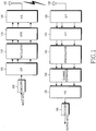
- FIG. 1 is a block diagram of a conventional OFDM mobile communication system. Its structure will be described in detail with reference to FIG. 1 .
- a channel encoder 100 For the input of bits, a channel encoder 100 outputs code symbols.
- a serial-to-parallel (S/P) converter 105 converts a serial code symbol sequence received from the channel encoder 100 to parallel symbol sequences.
- a modulator 110 maps the code symbol to a signal constellation by Quadrature Phase Shift Keying (QPSK), 8-ary Phase Shift Keying (8PSK), 16-ary Quadrature Amplitude Modulation (16QAM), or 64-ary Quadrature Amplitude Modulation (64QAM).
- QPSK Quadrature Phase Shift Keying
- 8PSK 8-ary Phase Shift Keying
- 16QAM 16-ary Quadrature Amplitude Modulation
- 64QAM 64-ary Quadrature Amplitude Modulation
- the number of bits forming a modulation symbol is preset for each of the modulations: a QPSK modulation symbol has 2 bits, a 8PSK modulation symbol has 3 bits, a 16QAM modulation symbol has 4 bits, and a 64QAM modulation symbol has 6 bits.
- An IFFT 115 inverse-fast-Fourier-transforms modulation symbols received from the modulator 110.
- a parallel-to-serial (P/S) converter 120 converts parallel symbols received from the IFFT 115 to a serial symbol sequence. The serial symbols are transmitted through a transmit antenna 125.
- a receive antenna 130 receives the symbols from the transmit antenna 125.
- a serial-to-parallel (S/P) converter 135 converts a received serial symbol sequence to parallel symbols.
- An FFT 140 fast-Fourier-transforms the parallel symbols.
- a demodulator 145 having the same signal constellation as used in the modulator 110, demodulates the FFT symbols to binary symbols by the signal constellation. The demodulation depends on the modulation.
- a channel estimator 150 channel-estimates the demodulated binary symbols. The channel estimation estimates situations involved in transmission of data from the transmit antenna, to thereby enable efficient data transmission.
- a P/S converter 155 converts the channel-estimated binary symbols to a serial symbol sequence.
- a decoder 160 decodes the serial binary symbols and outputs decoded binary bits.
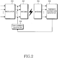
- FIG. 2 illustrates an operation in a Node B for assigning sub-carriers to a User Equipment (UE) in an OFDM mobile communication system.
- UE User Equipment
- Transmission data is modulated in a modulator 200 and transmitted through an antenna 202.
- the modulated data is transmitted on a plurality of sub-carriers.
- the Node B uses all of the sub-carriers or a selected part of the sub-carriers, for transmission of the modulated data.
- a feedback information generator 206 estimates the channel condition of data received through a receive antenna 204.
- the feedback information generator 206 measures the Signal-to-Interference power Ratio (SIR) or Channel-to-Noise Ratio (CNR) of the received signal. That is, the feedback information generator 206 measures the channel condition of an input signal transmitted on a particular channel (or sub-carrier and transmits the measurement to a sub-carrier allocator 208.
- Table 1 illustrates an example of feedback information that the feedback information generator 206 transmits to the sub-carrier allocator 208.
- data is transmitted on N sub-carriers.
- Feedback information a to g is an SIR or CNR generated from the feedback information generator 206.
- the sub-carrier allocator 208 determines a sub-carrier on which data is delivered based on the feedback information.
- the sub-carrier allocator 208 selects a sub-carrier having the highest SIR or CNR. If two or more sub-carriers are used between the Node B and the UE, as many sub-carriers having the highest SIRs or CNRs as required are selected sequentially.
- the sub-carrier allocator 208 assigns sub-carriers in the order of sub-carrier #0, sub-carrier #1, sub-carrier #3, sub-carrier #2, and so on. If one sub-carrier is needed, sub-carrier #0 is selected. If two sub-carriers are used, sub-carrier #0 and sub-carrier #1 are assigned. If three sub-carriers are used, sub-carrier #0, sub-carrier #1, and sub-carrier #3 are assigned. If four sub-carriers are used, sub-carrier #0, sub-carrier #1, sub-carrier #3 and sub-carrier #2 are assigned.
- the above-described sub-carrier assignment is performed in two stages: one is to arrange feedback information according to channel conditions and the other is to assign as many sub-carriers as needed to a UE based on the feedback information.
- the feedback information generator measures the channel condition for each subcarrier and transmits the channel condition measurement to the sub-carrier allocator.
- an existing mobile communication system is limited in the data rate at which uplink data is transmitted. Since the uplink is at a low rate, it is impossible to transmit the measured channel condition information to the Node B on the low-rate uplink.
- the sub-carrier assignment must be periodic and that is shorter than a coherence time.
- WO 02/49306 discloses a method and apparatus for subcarrier selection for systems is described.
- a method for subcarrier for a system employing orthogonal frequency division multiple access comprises partitioning subcarriers into groups of at least one cluster of subcarriers, receiving an indication of a selection by the subscriber of one or more groups in the groups, and allocating at least one cluster in the one or more groups of clusters selected by the subcarrier for use in communication with the subscriber.
- OFDMA orthogonal frequency division multiple access
- An object of the present invention is to substantially solve at least the above problems and/or disadvantages and to provide at least the advantages below. Accordingly, an object of the present invention is to provide an apparatus and method for reducing feedback information transmitted on an uplink.
- Another object of the present invention is to provide an apparatus and method for assigning different sub-carriers to a user equipment (UE) according to a varying channel condition.
- a further object of the present invention is to provide an apparatus and method for prioritizing UEs and assigning sub-carriers to the UEs according to their priority levels when the UEs request sub-carriers.
- an apparatus and method for assigning sub-carriers in an Orthogonal Frequency Division Multiplex (OFDM) system in an OFDM system that transmits data through at least one transmit antenna, assigning at least two sub-carriers in a predetermined frequency band to a UE, for data transmission.
- OFDM Orthogonal Frequency Division Multiplex
- a Node B groups sub-carriers available to the OFDM system into sub-carrier groups, each having at least two sub-carriers, transmits data to the UE on sub-carriers in the sub-carrier groups, selects at least one sub-carrier group for the UE based on channel condition information about each of the sub-carrier groups received from the UE, and assigns the selected sub-carrier group to the UE.
- an OFDM system that transmits data through at least one transmit antenna, assigning to at least two sub-carriers in a predetermined frequency band from a Node B, for data transmission.
- a UE receives from the Node B information about sub-carrier groups.
- the sub-carrier groups are produced by grouping sub-carriers available to the OFDM system, each having at least two sub-carriers.
- the UE then generates channel condition information about data received on sub-carriers of the sub-carrier groups and produces channel condition information about each of the sub-carrier groups.
- the UE transmits the channel condition information about the sub-carrier groups to the Node B.
- an OFDM system that transmits data through at least one transmit antenna, assigning at least two sub-carriers in a predetermined frequency band from a Node B to a UE.
- the Node B groups sub-carriers available to the OFDM system into sub-carrier groups, each having at least two sub-carriers, transmits data to the UE on sub-carriers in the sub-carrier groups, selects a sub-carrier group for the UE based on channel condition information about each of the sub-carrier groups received from the UE, and assigns the selected sub-carrier group to the UE.
- the UE generates channel condition information about data received on the sub-carriers of the sub-carrier groups, produces channel condition information about each of the sub-carrier groups, and transmits the channel condition information about the sub-carrier groups to the Node B.
- FIG. 3 is a block diagram illustrating an operation in a Node B for assigning sub-carriers to a user equipment (UE) in a single-antenna Orthogonal Frequency Division Multiplex (OFDM) system according to an embodiment of the present invention.
- One or more sub-carrier groups are set, each having a plurality of sub-carriers.
- the UE transmits feedback information on a per-sub-carrier group basis, not on a per-sub-carrier basis.
- the sub-carrier assignment to the UE in the Node B will be described with reference to FIG. 3 .
- N sub-carriers are available and grouped into G sub-carrier groups in an OFDM mobile communication system. Grouping of the sub-carriers will first be described.
- the number of sub-carrier groups may vary according to channel conditions. In the case of a channel experiencing serious frequency selective fading, the number of sub-carriers in one group is reduced, whereas in the case of a frequency flat fading channel, one group has more sub-carriers. Also, the data rate of the low-rate uplink may be considered. Therefore, G is determined according to the number of sub-carriers in each group.
- Sub-carriers can be selected for a sub-carrier group by Alternative Sub-carrier Allocation(ASA) or Sub-band Sub-carrier Allocation (SSA).
- ASA Sub-carrier Allocation
- SSA Sub-band Sub-carrier Allocation
- the ASA even numbered subcarriers (sub-carrier #0, sub-carrier #2, ..., sub-carrier #N-2) are included in a first group, and odd numbered subcarriers (sub-carrier #1, sub-carrier #3, ..., sub-carrier #N-1) are included in a second group.
- the SSA groups sub-carrier #0, sub-carrier #1, ..., sub-carrier #(N/2-1) in a first group, and sub-carrier #N/2, sub-carrier #(N/2+1), ..., sub-carrier #N-1 in a second group. It should be appreciated by those skilled in the art that the present invention is not limited to the ASA or SSA methods.
- the Node B selects sub-carriers for each sub-carrier group according to whether the UE requests packet data communication or circuit data communication and according to a desired quality of service (QoS).
- QoS quality of service
- the following description assumes the grouping of directly successive sub-carriers into one group. It should be obvious, however, that many other methods are applicable to the present invention including grouping sub-carriers spaced by a predetermined interval or longer into one group, or cyclically grouping sub-carriers in to every predetermined time periods, and the like. If the grouping method is changed, the Node B notifies the UE of the change in grouping by physical layer signaling or higher-layer signaling. This signaling is beyond the scope of the present invention and thus its detailed description is not provided here. For example, the physical layer signaling may take place on an existing High Speed-Downlink Packet Access (HS-DPA) channel, or a High Speed-Shared Control Channel (HS-SCCH).
- HS-DPA High Speed-Downlink Packet Access
- HS-SCCH High Speed-Shared Control Channel
- a plurality of groups, a modulator, a plurality of adders, a transmit antenna, a receive antenna, a feedback information generator, and a sub-carrier allocator are provided as illustrated in FIG. 3 .
- a modulator 300 modulates received signals and transmits the modulated signals to a plurality of groups.
- the number of the groups is determined according to the number of sub-carriers used and a coherent bandwidth.
- Each group assigns received modulated signals to sub-carriers. As stated, each group has successive sub-carriers.
- a first group 310 assigns received modulated signals to the sub-carriers of the first group 310 and transmits them to an adder 320.
- a G th group 312 assigns received modulated signals to the sub-carriers of the G th group 312 and transmits them to an adder 322.
- the adder 320 adds the received signals and transmits the sum to a transmit antenna 330, and the adder 322 adds the received signals and transmits the sum to the transmit antenna 330.
- the transmit antenna 330 transmits the signals to a receive antenna 340 on a radio channel.
- the receive antenna 340 transmits the signals received on the sub-carriers to a feedback information generator 350.
- the feedback information generator 350 sorts the signals by groups.
- the feedback information generator 350 measures the channel condition of signals received on sub-carriers in each group and transmits the measurement to a sub-carrier allocator 360. The operation of the feedback information generator 350 will be described later in more detail.
- the sub-carrier allocator 360 selects a sub-carrier group to be assigned to the UE based on the received channel condition information (i.e. feedback information).
- a base station (BS) communicates with the UE using the selected sub-carrier group.
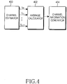
- FIG. 4 is a block diagram of the feedback information generator. With reference to FIG. 4 , the operation of the feedback information generator will now be described.
- the feedback information generator comprises a channel estimator 400, an average calculator 402, and a channel information generator 404.
- the channel estimator 400 channel-estimates a received signal.
- the channel estimation is performed on a sub-carrier basis.
- a Signal to Interference power Ratio SIR
- Signal to Interference plus Noise Ratio SINR
- Bit Error Rate BER
- Frame Error Rate FER
- CNR Channel-to-Noise Ratio
- An exemplary embodiment of the present invention takes the SIR into account. While sub-carriers in one group are used by way of example, the channel estimator 400 can channel-estimate all received sub-carriers.
- the average calculator 402 calculates the average of SIRs (channel estimate values) measured for the sub-carriers of a particular group in the channel estimator 400 and outputs the average SIR as a channel estimate value for the group. Receiving channel estimate values for all received sub-carriers, the average calculator 402 sorts the channel estimate values by groups and calculates the average of channel estimate values for each sub-carrier group.
- SIR g is the average of channel estimate values for the sub-carriers of a sub-carrier group
- SIR f is a channel estimate value for a sub-carrier
- L is the number of sub-carriers in one group
- G is the number of the groups
- f represents a sub-carrier.
- the average calculator 402 Upon receipt of channel estimate values for all received sub-carriers, the average calculator 402 computes the average channel estimate value for each group by Eq. (1).
- the average channel estimate values for the groups are illustrated in Table 2. Table 2 Group number Average channel estimate value 1 st group B 2 nd group A 3 rd group E 4 th group C ... ... G th group G
- the channel information generator 404 maps the average channel estimate values to predetermined values in a preset rule.
- An exemplary set of values to which the average channel estimate values are mapped are illustrated in Table 3.
- the average channel estimate values are mapped to four preset values in Table 3.
- the range of average channel estimate values mapped to the respective mapping values are adjusted by user selection.
- four mapping values are used in Table 3, the average channel estimate values can be mapped to at least two preset values by user selection.
- the average channel estimate values are classified into too many preset values, more bits are used to identify the present values, thereby increasing the volume of data on the uplink. Therefore, the number of mapping values is determined appropriately by taking the uplink into account.
- the ranges of average channel estimate values mapped to "00" and “11" are relatively wide, including A and B, and F and G, respectively, because the probability of the highest and lowest average channel estimate values is low. Since an intermediate average channel estimate value is highly probable, its range mapped to "10" is relatively narrow, thus including only E. Consequently, the probabilities of the mapping values are approximate.
- mapping values can be set by comparing the average channel estimate values with no regard to their absolute generation probabilities. For example, given four groups, "00” is assigned to a group having the highest average estimate value, and "01", "10” and “11” are sequentially assigned to the other groups in a descending order of average estimate values. This mapping method is adopted in an exemplary embodiment of the present invention, though many other methods are available.
- Table 4 illustrates an example of feedback information that the channel information generator 404 delivers to the sub-carrier allocator.
- Table 4 Group number Feedback information 1 st group 00 2 nd group 11 3 rd group 10 4 th group 01 ... ... G th group 11
- the sub-carrier allocator 360 selects a sub-carrier group to assign to the UE based on the feedback information. If the sub-carrier allocator 360 receives the feedback information illustrated in Table 4 and needs one sub-carrier group, it selects the 1 st group (with feedback of "00") and assigns the sub-carriers of the selected sub-carrier group to the UE. If two sub-carriers groups are needed, the sub-carrier allocator 360 assigns the sub-carriers of the first and fourth groups (feedback values of "00" and "01", respectively) to the UE.
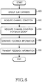
- FIG. 5 is a flowchart illustrating a Node B operation according to an embodiment of the present invention.
- the Node B groups sub-carriers into a plurality of sub-carrier groups according to the number of the sub-carriers and a coherent bandwidth in step 500. It is assumed that each group has successive sub-carriers. For reference, the sub-carriers of each sub-carrier group can be changed every predetermined time period. Otherwise, the same specific band might be repeatedly assigned to a particular user. For example, if a first sub-carrier group includes sub-carriers #0 to #5 at an initial transmission, it may have sub-carriers #2 to #7 a user-determined time later. Upon another time-out, the first group may have sub-carriers #4 to #9. Accordingly, sub-carriers in the other sub-carrier groups are also changed.
- step 502 the Node B assigns transmission data to the sub-carrier groups, that is, to the sub-carriers of each sub-carrier group.
- the Node B transmits the data to the UE in step 504.
- the Node B waits until feedback information is received in step 506.
- the feedback information represents the channel condition of each sub-carrier group.
- the channel condition of each sub-carrier group is the average channel condition values measured for the sub-carriers in the sub-carrier group.
- the Node B selects a sub-carrier group by which to transmit data to the UE.
- the Node B arranges the feedback information in an order of good channel condition and selects the sub-carrier group based on the feedback information.
- the Node B transmits data to the UE on sub-carriers belonging to the selected sub-carrier group in step 510.
- FIG. 6 is a flowchart illustrating a UE operation according to an embodiment of the present invention.
- step 600 the UE groups sub-carriers into a plurality of sub-carrier groups in the same manner as step 500 of FIG. 5 .
- the UE can receive formation about the sub-carrier groups set in the Node B on the same channel as a different channel from the channel on which the data is received.
- the UE measures the channel conditions (i.e. SNRs or CNRs) of received sub-carriers.
- the UE calculates the channel condition of each sub-carrier group using the channel condition measurements in step 604. Specifically, the UE rts the received sub-carriers by groups and calculates the average of the channel condition values of the sub-carriers in each sub-carrier group. This average is the channel condition of the sub-carrier group. Instead of calculating the average of e channel condition values of the sub-carriers in each sub-carrier group, they can summed.
- step 606 the UE generates feedback information from the channel condition formation for each sub-carrier group. If the channel condition information is the m of channel condition values for the sub-carriers in each sub-carrier group, the edback information is generated from channel estimate value sums rather than erage channel estimate values illustrated in Table 3. Assuming the sub-channels e weighted equally, the same result is achieved whether the averages or the ms are used in generating the feedback information in step 608, although in ernate embodiments, weighted calculations may be used.
- FIG. 7 is a block diagram of an OFDM mobile communication system using multiple transmit and receive antennas according to anembodiment of the present invention.
- Each transmit antenna transmits data on a plurality of sub-carriers at a predetermined frequency.
- a Node B for a Node B to assign sub-carriers to a UE, a plurality of groups, a modulator, a plurality of adders, transmit antennas, receive antennas, a feedback information generator, and a sub-carrier allocator are provided.
- a modulator 700 modulates received signals and transmits the modulated signals to a plurality of groups.
- the number of the groups is determined according to the number of sub-carriers used, a coherent bandwidth, and the number of transmit/receive antennas.
- Each group assigns received modulated signals to sub-carriers. As stated earlier, each group has successive sub-carriers.
- a first group 710 assigns received modulated signals to the sub-carriers of the first group 710 and transmits them to an adder 720.
- a G th group 712 assigns received modulated signals to the sub-carriers of the G th group 712 and transmits them to an adder 722.
- the adder 720 adds the received signals and transmits the sum to an antenna mapper 730, and the adder 722 adds the received signals and transmits the sum to the antenna mapper 730.
- the antenna mapper 730 assigns the sub-carrier groups to transmit antennas 740, 742 and 744.
- the antenna mapper 730 may assign the sub-carriers of a group to one or more transmit antennas. That is, the sub-carriers of the first group 710 are transmitted on at least one of the transmit antennas 740, 742 and 744. It is assumed hereinbelow that the antenna mapper 730 maps the sub-carriers of a group such that the sub-carriers are delivered to a receiver through the transmit antennas 740, 742 and 744.
- the sub-carrier groups are transmitted to receive antennas 750, 752 and 754 through the transmit antennas 740, 742 and 744. While the same number of transmit and receive antennas are used in FIG. 7 , the number of transmit and receive antennas can be controlled by user selection.
- the receive antennas 750, 752 and 754 deliver received sub-carrier groups to a feedback information generator 760.
- the feedback information generator 760 generates feedback information for the sub-carrier groups in the same manner as the feedback information generator 350 illustrated in FIG. 3 . Yet, the feedback information generator 760 generates more feedback information than the counterpart 350 and that of the respective transmit antennas 740, 742 and 744.
- Table 5 illustrates an example of the feedback information generated in the feedback information generator 760. Table 5 1 st group 2 nd group ... G th group Transmit antenna 740 00 01 ... 11 Transmit antenna 742 01 10 ... 01 ... ... ... ... ... ... Transmit antenna 744 01 10 ... 00
- the feedback information generator 760 generates the feedback information for each group and for transmit antenna as illustrated in Table 5 and transmits the feedback information to a sub-carrier allocator 770.
- the sub-carrier allocator 770 selects a sub-carrier group and a transmit antenna for a particular UE and controls the first to G th groups 710 to 712 and the antenna mapper 730 based on the selection information.
- Table 6 lists feedback information for each transmit antenna and for each UE for sub-carrier assignment in the sub-carrier allocator 770.
- the sub-carrier allocator 770 receiving the feedback information illustrated in Table 5 from two UEs each having two antennas, arranges the feedback information as illustrated in Table 6.
- Table 6 1 st group 2 nd group ... G th group 1 st transmit antenna, UE1 00 01 ... 11 1 st transmit antenna, UE2 01 00 ... 01 2 nd transmit antenna, UE 1 11 11 ... 10 2 nd transmit antenna, UE2 01 10 ... 00
- UE 1 has the best channel condition when data is transmitted on the sub-carriers of the first group through the first transmit antenna
- UE 2 has the best channel condition when data is transmitted on the sub-carriers of the second group through the first transmit antenna, or when data is transmitted on the sub-carriers of the G th group through the second transmit antenna. Therefore, the sub-carrier allocator 770 controls data to be transmitted to UE1 on the sub-carrier of the first group through the first transmit antenna, and to UE2 on the sub-carriers of the G th group through the second transmit antenna.
- a plurality of transmit antennas and a plurality of sub-carrier groups offer a good channel condition to a UE, they are prioritized according to a requested QoS and the type of a requested service. For example, when UE 1 requests packet data and UE 2 requests circuit data and the UEs are at the best channel condition for the same transmit antenna and sub-carrier group, the sub-carrier allocator 770 gives priority to UE 1 requesting packet data over UE 2 requesting circuit data. Yet, sub-carrier assignment criteria are implementation-dependent.
- FIG. 8 illustrates the format of feedback information transmitted from a UE to a Node B in the multi-antenna system according to an embodiment of the present invention. Since the UE and the Node B are aware of the grouping of the sub-carriers, the UE transmits feedback information indexes for the first group to the G th group without any particular indexes for the groups and the Node B assigns a sub-carrier group to the UE based on the received information.
- the feedback information may be transmitted on the HS-DPCCH for HS-DPA, for example.
- the present invention effects single or multi-antenna select diversity in OFDM. Also, transmission of uplink feedback information on a per-sub-carrier group basis leads to efficient use of radio resources.
Landscapes
- Engineering & Computer Science (AREA)
- Signal Processing (AREA)
- Computer Networks & Wireless Communication (AREA)
- Quality & Reliability (AREA)
- Mobile Radio Communication Systems (AREA)
- Radio Transmission System (AREA)
Claims (13)
- Procédé destiné à être utilisé dans un noeud B pour l'assignation d'au moins deux sous-porteuses dans une bande de fréquences prédéterminée pour transmettre des données à destination d'un équipement d'utilisateur, UE, pour une utilisation dans un système de multiplexage par répartition de fréquence orthogonale, OFDM, le procédé comprenant les étapes de :la transmission de données à destination de l'UE sur des sous-porteuses d'une pluralité de groupes de sous-porteuses depuis une pluralité d'antennes de transmission, dans lequel chaque groupe de sous-porteuses comprend au moins deux sous-porteuses adjacentes ;la réception d'informations de conditions de canal relatives à chacun de la pluralité de groupes de sous-porteuses pour chaque antenne de transmission du noeud B en provenance de l'UE ;la sélection d'un groupe de sous-porteuses pour l'UE, qui doit être utilisé pour une transmission de données et la sélection d'une antenne de transmission pour une transmission des données, par ordre décroissant des informations de conditions de canal ; etla transmission de données sur le groupe de sous-porteuses sélectionné, par l'intermédiaire de l'antenne de transmission sélectionnée,dans lequel les informations de conditions de canal comprennent des valeurs représentant des conditions de canal pour chaque groupe de sous-porteuses et chaque antenne de transmission.
- Procédé selon la revendication 1, dans lequel les sous-porteuses des groupes de sous-porteuses sont changées à une période de temps prédéterminée.
- Procédé selon la revendication 1, dans lequel les informations de conditions de canal relatives à chacun des groupes de sous-porteuses comprennent une moyenne des rapports de signal sur bruit, SNR, de sous-porteuses incluses dans le groupe de sous-porteuses.
- Procédé selon la revendication 1, dans lequel l'étape de la sélection comprend en outre l'étape de :
l'assignation du groupe de sous-porteuses à l'UE en fonction d'une qualité de service et d'un type d'un service demandé par l'UE si le noeud B reçoit des informations de conditions de canal relatives aux groupes de sous-porteuses en provenance d'au moins deux UE. - Procédé destiné à être utilisé dans un équipement d'utilisateur, UE, pour l'assignation d'au moins deux sous-porteuses dans une bande de fréquences prédéterminée pour recevoir des données en provenance d'un noeud B pour une utilisation dans un système de multiplexage par répartition de fréquence orthogonale, OFDM, le procédé comprenant les étapes de :la réception de données transmises par le noeud B sur des sous-porteuses d'une pluralité de groupes de sous-porteuses en provenance d'une pluralité d'antennes de transmission, dans lequel chaque groupe de sous-porteuses comprend au moins deux sous-porteuses adjacentes ;la génération (606) d'informations de conditions de canal relatives à chacun de la pluralité de groupes de sous-porteuses utilisés pour une transmission de données pour chacune de la pluralité d'antennes de transmission du noeud B ;la transmission (608) des informations de conditions de canal à destination du noeud B ; etla réception de données transmises par le noeud B sur un groupe de sous-porteuses par l'intermédiaire d'une antenne de transmission,dans lequel le groupe de sous-porteuses et l'antenne de transmission sont déterminés pour une transmission de données par ordre décroissant des informations de conditions de canal ;dans lequel les informations de conditions de canal comprennent des valeurs représentant des conditions de canal pour chaque groupe de sous-porteuses et chaque antenne de transmission.
- Procédé selon la revendication 5, dans lequel un rapport de signal sur bruit, SNR, de sous-porteuses des groupes de sous-porteuses est calculé par l'utilisation de données reçues sur des sous-porteuses des groupes de sous-porteuses.
- Procédé selon la revendication 6, dans lequel les informations de conditions de canal relatives à chacun des groupes de sous-porteuses comprennent une moyenne des SNR de sous-porteuses incluses dans le groupe de sous-porteuses.
- Procédé selon la revendication 6, dans lequel les informations de conditions de canal relatives à chacun des groupes de sous-porteuses comprennent une somme des SNR de sous-porteuses incluses dans le groupe de sous-porteuses.
- Procédé selon la revendication 5, dans lequel les sous-porteuses des groupes de sous-porteuses sont changées à une période de temps prédéterminée.
- Appareil pour un noeud B pour l'assignation d'au moins deux sous-porteuses dans une bande de fréquences prédéterminée pour transmettre des données à destination d'un équipement d'utilisateur, UE, pour une utilisation dans un système de multiplexage par répartition de fréquence orthogonale, OFDM, l'appareil comprenant :une pluralité d'antennes de transmission (740, 742, 743, 744) pour la transmission de données à destination de l'UE sur des sous-porteuses d'une pluralité de groupes de sous-porteuses, dans lequel chaque groupe de sous-porteuses comprend au moins deux sous-porteuses adjacentes ;un modulateur (700) pour la modulation de données ;un organe de commande (770) pour la réception d'informations de conditions de canal relatives à chacun de la pluralité de groupes de sous-porteuses pour chacune de la pluralité d'antennes de transmission du noeud B en provenance de l'UE, et pour la sélection d'un groupe de sous-porteuses pour l'UE, qui doit être utilisé pour la transmission des données et la sélection d'une antenne de transmission pour la transmission des données, par ordre décroissant d'une condition des informations de conditions de canal ;un processeur de signal pour la mise en concordance des données avec les groupes de sous-porteuses sélectionnés sous le contrôle de l'organe de commande ; etun émetteur (730) pour l'assignation des données mises en concordance avec le groupe de sous-porteuses sélectionné à l'antenne de transmission sélectionnée sous le contrôle de l'organe de commande, et pour la transmission des données sur le groupe de sous-porteuses sélectionné à destination de l'UE par l'intermédiaire de l'antenne de transmission sélectionnée,dans lequel les informations de conditions de canal comprennent des valeurs représentant des conditions de canal pour chaque groupe de sous-porteuses et chaque antenne de transmission.
- Appareil selon la revendication 10, dans lequel le noeud B change les sous-porteuses du groupe de sous-porteuses à une période de temps prédéterminée.
- Appareil selon la revendication 10, dans lequel, si le noeud B reçoit les informations de conditions de canal relatives aux groupes de sous-porteuses en provenance d'au moins deux UE,
le noeud B effectue l'assignation du groupe de sous-porteuses à l'UE en fonction d'une qualité de service et d'un type d'un service demandé par l'UE. - Appareil pour un équipement d'utilisateur, UE, pour la réception de données en provenance d'un noeud B pour une utilisation dans un système de multiplexage par répartition de fréquence orthogonale, OFDM, l'appareil comprenant :un démodulateur pour la réception de données transmises par le noeud B sur des sous-porteuses d'une pluralité de groupes de sous-porteuses en provenance d'une pluralité d'antennes de transmission (740 ; 742, 744), dans lequel chaque groupe de sous-porteuses comprend au moins deux sous-porteuses adjacentes ;un générateur d'informations de rétroaction (760) pour la génération d'informations de conditions de canal relatives à chacun de la pluralité de groupes de sous-porteuses utilisés pour une transmission de données pour chacune de la pluralité d'antennes de transmission du noeud B ; etun émetteur pour la transmission des informations de conditions de canal à destination du noeud B ;dans lequel le démodulateur effectue en outre la réception de données transmises par le noeud B sur un groupe de sous-porteuses par l'intermédiaire d'une antenne de transmission, et le groupe de sous-porteuses et l'antenne de transmission sont déterminés pour une transmission des données par ordre décroissant des informations de conditions de canal, etdans lequel les informations de conditions de canal comprennent des valeurs représentant des conditions de canal pour chaque groupe de sous-porteuses et chaque antenne de transmission.
Applications Claiming Priority (2)
| Application Number | Priority Date | Filing Date | Title |
|---|---|---|---|
| KR2003058426 | 2003-08-22 | ||
| KR10-2003-0058426A KR100539925B1 (ko) | 2003-08-22 | 2003-08-22 | 직교주파수분할다중 시스템에서 부반송파 할당 장치 및 방법 |
Publications (2)
| Publication Number | Publication Date |
|---|---|
| EP1509016A1 EP1509016A1 (fr) | 2005-02-23 |
| EP1509016B1 true EP1509016B1 (fr) | 2018-11-14 |
Family
ID=34056946
Family Applications (1)
| Application Number | Title | Priority Date | Filing Date |
|---|---|---|---|
| EP04018458.2A Expired - Lifetime EP1509016B1 (fr) | 2003-08-22 | 2004-08-04 | Appareil et méthode pour assigner des groupes de sous-porteuses dans un système OFDM |
Country Status (5)
| Country | Link |
|---|---|
| US (1) | US7545732B2 (fr) |
| EP (1) | EP1509016B1 (fr) |
| JP (1) | JP4046712B2 (fr) |
| KR (1) | KR100539925B1 (fr) |
| CN (1) | CN1585394B (fr) |
Families Citing this family (93)
| Publication number | Priority date | Publication date | Assignee | Title |
|---|---|---|---|---|
| US8670390B2 (en) | 2000-11-22 | 2014-03-11 | Genghiscomm Holdings, LLC | Cooperative beam-forming in wireless networks |
| US10355720B2 (en) | 2001-04-26 | 2019-07-16 | Genghiscomm Holdings, LLC | Distributed software-defined radio |
| US9819449B2 (en) | 2002-05-14 | 2017-11-14 | Genghiscomm Holdings, LLC | Cooperative subspace demultiplexing in content delivery networks |
| US10931338B2 (en) | 2001-04-26 | 2021-02-23 | Genghiscomm Holdings, LLC | Coordinated multipoint systems |
| US9628231B2 (en) | 2002-05-14 | 2017-04-18 | Genghiscomm Holdings, LLC | Spreading and precoding in OFDM |
| US10644916B1 (en) | 2002-05-14 | 2020-05-05 | Genghiscomm Holdings, LLC | Spreading and precoding in OFDM |
| US10200227B2 (en) | 2002-05-14 | 2019-02-05 | Genghiscomm Holdings, LLC | Pre-coding in multi-user MIMO |
| US10142082B1 (en) | 2002-05-14 | 2018-11-27 | Genghiscomm Holdings, LLC | Pre-coding in OFDM |
| KR100566274B1 (ko) * | 2003-11-20 | 2006-03-30 | 삼성전자주식회사 | 직교주파수분할다중 시스템에서 부반송파 할당 장치 및방법 |
| WO2006000955A1 (fr) * | 2004-06-24 | 2006-01-05 | Philips Intellectual Property & Standards Gmbh | Procede de signalisation de l'etat d'une sous-porteuse dans un reseau a porteuses multiples (pm) et procede d'attribution adaptative des sous-porteuses dans un reseau pm |
| US11552737B1 (en) | 2004-08-02 | 2023-01-10 | Genghiscomm Holdings, LLC | Cooperative MIMO |
| US11381285B1 (en) | 2004-08-02 | 2022-07-05 | Genghiscomm Holdings, LLC | Transmit pre-coding |
| US11184037B1 (en) | 2004-08-02 | 2021-11-23 | Genghiscomm Holdings, LLC | Demodulating and decoding carrier interferometry signals |
| EP2490494B1 (fr) * | 2004-10-20 | 2016-05-11 | Qualcomm Incorporated | Fonctionnement sur bande a frequences multiples dans des reseaux sans fil |
| KR100764789B1 (ko) | 2004-11-16 | 2007-10-11 | 엘지전자 주식회사 | 직교 주파수 분할 다중(ofdm)시스템에서의 신호전송장치 및 방법 |
| EP1679814B1 (fr) | 2005-01-11 | 2018-01-10 | Samsung Electronics Co., Ltd. | Dispositif et procédé de transmission d'une information de rétroaction dans un système de communication sans fil |
| US8135088B2 (en) * | 2005-03-07 | 2012-03-13 | Q1UALCOMM Incorporated | Pilot transmission and channel estimation for a communication system utilizing frequency division multiplexing |
| RU2408987C2 (ru) * | 2005-04-01 | 2011-01-10 | Нтт Досомо, Инк. | Передающее устройство и способ передачи сигнала |
| EP1722583A1 (fr) * | 2005-05-11 | 2006-11-15 | Siemens Aktiengesellschaft | Beam-hopping dans un système de radiocommunication |
| KR100768511B1 (ko) | 2005-07-19 | 2007-10-18 | 한국전자통신연구원 | Mc-cdma 시스템의 기지국 송신기, 그 시스템의 송신다이버시티 방법, 분산 mc-cdma 시스템의 기지국송신기 및 그 시스템의 송신 다이버시티 방법 |
| US8229448B2 (en) * | 2005-08-01 | 2012-07-24 | Samsung Electronics Co., Ltd. | Apparatus and method for adaptive channel quality feedback in a multicarrier wireless network |
| DE602005027618D1 (de) * | 2005-08-02 | 2011-06-01 | Mitsubishi Electric Corp | Kommunikationseinrichtung und funkkommunikationssystem |
| US8077690B2 (en) * | 2005-08-24 | 2011-12-13 | Motorola Mobility, Inc. | Resource allocation in cellular communication systems |
| WO2007023151A1 (fr) * | 2005-08-24 | 2007-03-01 | Nokia Siemens Networks Gmbh & Co. Kg | Procede de configuration d'une interface radio de systeme de communication radio |
| JP4664980B2 (ja) * | 2005-08-25 | 2011-04-06 | 富士通株式会社 | 移動端末及び基地局装置 |
| CN1953437B (zh) * | 2005-10-17 | 2010-09-29 | 北京三星通信技术研究有限公司 | 基于子载波宽度不变的可扩展ofdm系统和方法 |
| US8054894B2 (en) * | 2005-10-31 | 2011-11-08 | Motorola Mobility, Inc. | Method and apparatus for providing channel quality feedback in an orthogonal frequency division multiplexing communication system |
| CN1777161B (zh) * | 2005-12-02 | 2010-04-28 | 山东大学 | 一种移动宽带信道中的自适应选频分块传输方法 |
| KR100788890B1 (ko) * | 2005-12-07 | 2007-12-27 | 한국전자통신연구원 | 다중안테나를 사용하는 다중 반송파 시스템의 송신 장치 및 수신 장치 |
| KR100819033B1 (ko) * | 2005-12-07 | 2008-04-02 | 한국전자통신연구원 | 통계적 부반송파 다중화 및 부반송파 다중 접속 장치 및방법 |
| US8412249B2 (en) * | 2005-12-20 | 2013-04-02 | Alcatel Lucent | Resource allocation based on interference mitigation in a wireless communication system |
| EP1965529A4 (fr) * | 2005-12-20 | 2014-03-05 | Huawei Tech Co Ltd | Systeme de communication, station de base et stations utilisees dans ledit systeme |
| JP5311711B2 (ja) * | 2005-12-22 | 2013-10-09 | 京セラ株式会社 | 通信制御システム、無線通信端末及び通信制御方法 |
| WO2007081181A2 (fr) * | 2006-01-13 | 2007-07-19 | Lg Electronics Inc. | Procédé et appareil destinés à obtenir une diversité d'émission et un multiplexage spatial au moyen d'une sélection d'antenne basée sur des informations de rétroaction |
| WO2007108077A1 (fr) * | 2006-03-17 | 2007-09-27 | Fujitsu Limited | Dispositif de station de base, dispositif de station mobile et procédé d'affectation d'une sous-porteuse |
| GB2436416A (en) * | 2006-03-20 | 2007-09-26 | Nec Corp | Signal resource allocation in a communication system using a plurality of subcarriers |
| WO2007126014A1 (fr) | 2006-04-28 | 2007-11-08 | Panasonic Corporation | Dispositif de station de base de communication radio, procede de communication utilise pour une communication multi-porteuse |
| US8189621B2 (en) | 2006-05-12 | 2012-05-29 | Microsoft Corporation | Stack signaling to application with lack of requested bandwidth |
| EP2039194A1 (fr) * | 2006-07-11 | 2009-03-25 | Nokia Corporation | Procédé de transmission de données, station de base et émetteur/récepteur utilisateur |
| KR100957311B1 (ko) * | 2006-08-11 | 2010-05-13 | 삼성전자주식회사 | 이동통신 시스템에서 상향링크의 스케쥴링 방법 및 장치 |
| US7483700B2 (en) * | 2006-08-14 | 2009-01-27 | Motorola, Inc. | Method and apparatus for determining appropriate channels for communication |
| DK2421318T3 (da) | 2006-08-21 | 2013-06-10 | Interdigital Tech Corp | Metode og apparat til at transmittere planlægningsinformation i et trådløst kommunikationssystem |
| KR100878768B1 (ko) * | 2006-09-15 | 2009-01-14 | 삼성전자주식회사 | Mimo ofdm 송수신 방법 및 장치 |
| WO2008035706A1 (fr) * | 2006-09-20 | 2008-03-27 | Sharp Kabushiki Kaisha | Dispositif de communication radio, système de communication radio et procédé de communication radio |
| TW201616905A (zh) | 2006-10-10 | 2016-05-01 | 內數位科技公司 | 為船送至多數無線傳送/接收單元下鏈分享服務發送反饋之方法及裝置 |
| US7860500B2 (en) * | 2006-10-27 | 2010-12-28 | Motorola, Inc. | Method and apparatus for determining appropriate channels for communication |
| JP4898400B2 (ja) * | 2006-11-24 | 2012-03-14 | シャープ株式会社 | 無線送信装置、無線受信装置、無線通信システムおよび無線通信方法 |
| US8144793B2 (en) | 2006-12-12 | 2012-03-27 | Microsoft Corporation | Cognitive multi-user OFDMA |
| KR101341466B1 (ko) * | 2006-12-18 | 2013-12-16 | 엘지전자 주식회사 | 통신 시스템에서의 적응적 자원 할당 방법 및 이를구현하는 송수신기 |
| KR20130045390A (ko) * | 2007-03-15 | 2013-05-03 | 인터디지탈 테크날러지 코포레이션 | 무선 통신에서의 피드백 오버헤드 감소를 위한 방법 및 장치 |
| KR100985395B1 (ko) | 2007-04-03 | 2010-10-05 | 연세대학교 산학협력단 | 직교주파수 분할다중화 통신시스템에서 전송 장치 및 방법 |
| US7990920B2 (en) * | 2007-04-26 | 2011-08-02 | Samsung Electronics Co., Ltd. | Transmit diversity for acknowledgement and category 0 bits in a wireless communication system |
| US7970085B2 (en) | 2007-05-08 | 2011-06-28 | Microsoft Corporation | OFDM transmission and reception for non-OFDMA signals |
| CN101772933B (zh) * | 2007-08-07 | 2015-06-17 | 夏普株式会社 | 通信装置以及接收质量信息生成方法 |
| EP2026488A1 (fr) * | 2007-08-14 | 2009-02-18 | Panasonic Corporation | Rapport ACQ contigu |
| EP2207288A1 (fr) * | 2007-10-25 | 2010-07-14 | Sharp Kabushiki Kaisha | Dispositif de communication, système de communication à multiples porteuses, et procédé de communication |
| DE602007010654D1 (de) * | 2007-12-19 | 2010-12-30 | Sony Corp | Optimale BER-Einstellung zur adaptiven Mehrträgermodulation |
| US8374130B2 (en) | 2008-01-25 | 2013-02-12 | Microsoft Corporation | Orthogonal frequency division multiple access with carrier sense |
| CN101252384B (zh) * | 2008-03-28 | 2012-02-22 | 清华大学 | 基于ofdm和跨层设计的星载交换方法 |
| KR101452504B1 (ko) * | 2008-06-18 | 2014-10-23 | 엘지전자 주식회사 | Vht 무선랜 시스템에서의 채널 접속 방법 및 이를지원하는 스테이션 |
| CN101582739A (zh) * | 2008-06-27 | 2009-11-18 | 北京新岸线移动多媒体技术有限公司 | 数字广播信号的发送装置、发送方法和发送系统 |
| CN101582740A (zh) * | 2008-06-27 | 2009-11-18 | 北京新岸线移动多媒体技术有限公司 | 数字广播信号的发送装置、发送方法和发送系统 |
| KR101240373B1 (ko) | 2008-08-29 | 2013-03-11 | 인터디지탈 패튼 홀딩스, 인크 | 다운링크 공유 서비스에 대한 피드백 신호를 전송하고 무선 송수신 유닛의 갯수를 추정하기 위한 방법 및 장치 |
| KR101587680B1 (ko) | 2008-10-20 | 2016-01-21 | 인터디지탈 패튼 홀딩스, 인크 | 반송파 집적 방법 |
| CN101488829B (zh) * | 2009-01-24 | 2011-12-28 | 华为技术有限公司 | 频带自适应编码业务处理方法、基站和终端 |
| KR101032224B1 (ko) * | 2009-03-06 | 2011-05-02 | 삼성전기주식회사 | Ofdm 시스템의 채널상태정보(csi)의 생성 장치 및 방법 |
| CN102484869B (zh) | 2009-06-19 | 2015-09-16 | 交互数字专利控股公司 | 在lte-a中用信号发送上行链路控制信息 |
| WO2011025825A1 (fr) | 2009-08-25 | 2011-03-03 | Interdigital Patent Holdings, Inc. | Procédé et appareil pour gérer des communications de groupe |
| CN103036660B (zh) | 2010-04-30 | 2015-09-16 | 北京三星通信技术研究有限公司 | 一种反馈数据接收状况的方法 |
| CN101848063B (zh) * | 2010-05-21 | 2016-06-08 | 北京新岸线移动多媒体技术有限公司 | 支持子信道调制编码的数据传输方法及无线局域网系统 |
| JP5489891B2 (ja) * | 2010-07-07 | 2014-05-14 | 株式会社Nttドコモ | 移動通信システムにおける基地局及び方法 |
| KR101533793B1 (ko) * | 2010-09-28 | 2015-07-09 | 한국전자통신연구원 | 다중안테나 시스템에서 안테나 선택방법 및 장치 |
| GB2493702B (en) * | 2011-08-11 | 2016-05-04 | Sca Ipla Holdings Inc | OFDM subcarrier allocations in wireless telecommunications systems |
| WO2014012235A1 (fr) * | 2012-07-19 | 2014-01-23 | 华为技术有限公司 | Procédé pour une configuration adaptative de ressources dans le domaine fréquentiel, appareil, et système de communication |
| US9936502B2 (en) | 2013-12-18 | 2018-04-03 | Huawei Technologies Co., Ltd. | System and method for OFDMA resource management in WLAN |
| US9755795B2 (en) * | 2013-12-18 | 2017-09-05 | Huawei Technologies Co., Ltd. | System and method for WLAN OFDMA design of subcarrier groups and frame format |
| US12224860B1 (en) | 2014-01-30 | 2025-02-11 | Genghiscomm Holdings, LLC | Linear coding in decentralized networks |
| DE102015205478A1 (de) * | 2015-03-26 | 2016-09-29 | Bayerische Motoren Werke Aktiengesellschaft | Verfahren und Vorrichtung zur Konfiguration einer Übertragungsverbindung |
| JP6440075B2 (ja) * | 2015-06-22 | 2018-12-19 | 日本電信電話株式会社 | 無線通信方法および無線通信装置 |
| MX2021004799A (es) * | 2015-07-23 | 2022-12-07 | Samsung Electronics Co Ltd | Aparato de transmision, aparato de recepcion, y metodos de control de los mismos. |
| CN106685495A (zh) * | 2015-11-05 | 2017-05-17 | 索尼公司 | 无线通信方法和无线通信设备 |
| US9847802B1 (en) * | 2016-08-16 | 2017-12-19 | Xilinx, Inc. | Reconfiguration of single-band transmit and receive paths to multi-band transmit and receive paths in an integrated circuit |
| US10637705B1 (en) | 2017-05-25 | 2020-04-28 | Genghiscomm Holdings, LLC | Peak-to-average-power reduction for OFDM multiple access |
| US10243773B1 (en) | 2017-06-30 | 2019-03-26 | Genghiscomm Holdings, LLC | Efficient peak-to-average-power reduction for OFDM and MIMO-OFDM |
| CN108627818B (zh) * | 2018-03-19 | 2023-11-17 | 桂林电子科技大学 | 基于ofdm的频控阵雷达通信一体化波形设计方法 |
| US11343823B2 (en) | 2020-08-16 | 2022-05-24 | Tybalt, Llc | Orthogonal multiple access and non-orthogonal multiple access |
| US12206535B1 (en) | 2018-06-17 | 2025-01-21 | Tybalt, Llc | Artificial neural networks in wireless communication systems |
| EP3915236A4 (fr) | 2019-01-25 | 2023-05-24 | Genghiscomm Holdings, LLC | Accès multiple orthogonal, et accès multiple non orthogonal |
| WO2020242898A1 (fr) | 2019-05-26 | 2020-12-03 | Genghiscomm Holdings, LLC | Accès multiple non orthogonal |
| CN113993142B (zh) * | 2020-07-27 | 2025-03-11 | 华为技术有限公司 | 通信方法及装置 |
| CN111884980B (zh) * | 2020-08-03 | 2021-07-27 | 兰州理工大学 | 一种无线光通信的广义索引调制光ofdm调制方法 |
| US12170584B2 (en) * | 2021-04-01 | 2024-12-17 | Telefonaktiebolaget Lm Ericsson (Publ) | Channel estimation for wireless communication network |
| CN116015586B (zh) * | 2022-12-29 | 2025-06-10 | 广东电网有限责任公司 | 电力线通信子载波的分组聚合方法、装置、设备及介质 |
Family Cites Families (20)
| Publication number | Priority date | Publication date | Assignee | Title |
|---|---|---|---|---|
| US5726978A (en) * | 1995-06-22 | 1998-03-10 | Telefonaktiebolaget L M Ericsson Publ. | Adaptive channel allocation in a frequency division multiplexed system |
| JP3670445B2 (ja) | 1997-06-30 | 2005-07-13 | 株式会社東芝 | 無線通信システム |
| US6131016A (en) * | 1997-08-27 | 2000-10-10 | At&T Corp | Method and apparatus for enhancing communication reception at a wireless communication terminal |
| JP2962299B2 (ja) | 1998-01-09 | 1999-10-12 | 日本電信電話株式会社 | マルチキャリア信号伝送装置 |
| JP2000114846A (ja) | 1998-10-06 | 2000-04-21 | Toshiba Corp | 指向性アンテナ選択システム、指向性アンテナ選択方法、指向性アンテナ基地局、及び無線端末 |
| JP2000209145A (ja) | 1999-01-20 | 2000-07-28 | Nippon Telegr & Teleph Corp <Ntt> | マルチキャリア信号送受信装置 |
| JP3826653B2 (ja) | 2000-02-25 | 2006-09-27 | Kddi株式会社 | 無線通信システムのサブキャリア割当方法 |
| JP2001358692A (ja) * | 2000-06-14 | 2001-12-26 | Nec Corp | 直交周波数分割多重変復調回路 |
| US7072315B1 (en) | 2000-10-10 | 2006-07-04 | Adaptix, Inc. | Medium access control for orthogonal frequency-division multiple-access (OFDMA) cellular networks |
| US6947748B2 (en) * | 2000-12-15 | 2005-09-20 | Adaptix, Inc. | OFDMA with adaptive subcarrier-cluster configuration and selective loading |
| CA2431849C (fr) * | 2000-12-15 | 2013-07-30 | Broadstrom Telecommunications, Inc. | Communications a ondes porteuses multiples avec attribution d'ondes porteuses basee sur des groupes |
| EP1453229A4 (fr) | 2001-08-30 | 2007-07-11 | Fujitsu Ltd | Systeme et procede d'emission amrc a porteuses multiples |
| JP3875079B2 (ja) | 2001-11-16 | 2007-01-31 | ソフトバンクテレコム株式会社 | 直交周波数分割多重システムおよび送受信装置 |
| JP3875086B2 (ja) | 2001-11-30 | 2007-01-31 | ソフトバンクテレコム株式会社 | 直交周波数分割多重システムおよび送受信装置 |
| JP3955463B2 (ja) | 2001-12-05 | 2007-08-08 | ソフトバンクテレコム株式会社 | 直交周波数分割多重通信システム |
| US7020110B2 (en) | 2002-01-08 | 2006-03-28 | Qualcomm Incorporated | Resource allocation for MIMO-OFDM communication systems |
| KR100547848B1 (ko) * | 2002-01-16 | 2006-02-01 | 삼성전자주식회사 | 다중 반송파 이동통신시스템에서 순방향 채널 상태 정보송수신 방법 및 장치 |
| EP1492258B1 (fr) | 2002-03-29 | 2017-04-19 | Inventergy, Inc. | Procédé de retransmission de données dans un système de transmission et de communication a porteuses multiples présentant un dispositif de contrôle de retransmission de données |
| US7236512B2 (en) * | 2002-09-09 | 2007-06-26 | Qualcomm Incorporated | Code channel allocations in a wireless communications system |
| KR100566274B1 (ko) * | 2003-11-20 | 2006-03-30 | 삼성전자주식회사 | 직교주파수분할다중 시스템에서 부반송파 할당 장치 및방법 |
-
2003
- 2003-08-22 KR KR10-2003-0058426A patent/KR100539925B1/ko not_active Expired - Fee Related
-
2004
- 2004-08-04 EP EP04018458.2A patent/EP1509016B1/fr not_active Expired - Lifetime
- 2004-08-19 US US10/921,149 patent/US7545732B2/en active Active
- 2004-08-20 JP JP2004241634A patent/JP4046712B2/ja not_active Expired - Fee Related
- 2004-08-20 CN CN2004100575791A patent/CN1585394B/zh not_active Expired - Fee Related
Non-Patent Citations (1)
| Title |
|---|
| None * |
Also Published As
| Publication number | Publication date |
|---|---|
| JP4046712B2 (ja) | 2008-02-13 |
| JP2005073259A (ja) | 2005-03-17 |
| US20070140102A1 (en) | 2007-06-21 |
| CN1585394B (zh) | 2011-12-21 |
| EP1509016A1 (fr) | 2005-02-23 |
| CN1585394A (zh) | 2005-02-23 |
| KR100539925B1 (ko) | 2005-12-28 |
| US7545732B2 (en) | 2009-06-09 |
| KR20050020457A (ko) | 2005-03-04 |
Similar Documents
| Publication | Publication Date | Title |
|---|---|---|
| EP1509016B1 (fr) | Appareil et méthode pour assigner des groupes de sous-porteuses dans un système OFDM | |
| US11411702B2 (en) | Method and apparatus for generating pilot tone in orthogonal frequency division multiplexing access system, and method and apparatus for estimating channel using it | |
| US7423991B2 (en) | Apparatus and method for allocating subchannels adaptively according to frequency reuse rates in an orthogonal frequency division multiple access system | |
| KR100566274B1 (ko) | 직교주파수분할다중 시스템에서 부반송파 할당 장치 및방법 | |
| US7567625B2 (en) | Apparatus and method for sub-carrier allocation in a multiple-input and multiple-output (MIMO) orthogonal frequency division multiplexing (OFDM) communication system | |
| KR100571806B1 (ko) | 적응적 ofdma 시스템에서 궤환되는 채널 상태 정보를줄이기 위한 방법 및 이를 사용하는 적응적 ofdma시스템 | |
| US7526035B2 (en) | Apparatus and method for switching between an AMC mode and a diversity mode in a broadband wireless communication system | |
| US8571132B2 (en) | Constrained hopping in wireless communication systems | |
| US7502310B2 (en) | Apparatus and method for assigning subchannel in a mobile communication system using orthogonal frequency division multiple access scheme | |
| EP1492280B1 (fr) | L'affectation adaptative des canaux sur la base de la qualité dans un système de radio communication OFDMA | |
| US20050281226A1 (en) | Apparatus and method for feedback of channel quality information in communication systems using an OFDM scheme | |
| US20050180313A1 (en) | Apparatus and method for controlling adaptive modulation and coding in an orthogonal frequency division multiplexing communication system | |
| US20070230327A1 (en) | Transmitting apparatus and method in an orthogonal frequency division multiplexing system | |
| KR20050005993A (ko) | 직교 주파수 분할 다중 방식을 사용하는 이동 통신시스템에서 적응적 변조 및 코딩 방식 제어 장치 및 방법 |
Legal Events
| Date | Code | Title | Description |
|---|---|---|---|
| PUAI | Public reference made under article 153(3) epc to a published international application that has entered the european phase |
Free format text: ORIGINAL CODE: 0009012 |
|
| 17P | Request for examination filed |
Effective date: 20040804 |
|
| AK | Designated contracting states |
Kind code of ref document: A1 Designated state(s): AT BE BG CH CY CZ DE DK EE ES FI FR GB GR HU IE IT LI LU MC NL PL PT RO SE SI SK TR |
|
| AX | Request for extension of the european patent |
Extension state: AL HR LT LV MK |
|
| AKX | Designation fees paid |
Designated state(s): DE FR GB IT |
|
| 17Q | First examination report despatched |
Effective date: 20100427 |
|
| RAP1 | Party data changed (applicant data changed or rights of an application transferred) |
Owner name: SAMSUNG ELECTRONICS CO., LTD. |
|
| REG | Reference to a national code |
Ref country code: DE Ref legal event code: R079 Ref document number: 602004053412 Country of ref document: DE Free format text: PREVIOUS MAIN CLASS: H04L0027260000 Ipc: H04B0007060000 |
|
| GRAP | Despatch of communication of intention to grant a patent |
Free format text: ORIGINAL CODE: EPIDOSNIGR1 |
|
| RIC1 | Information provided on ipc code assigned before grant |
Ipc: H04B 7/06 19680901AFI20180524BHEP Ipc: H04L 5/00 19680901ALI20180524BHEP Ipc: H04L 1/00 19680901ALI20180524BHEP |
|
| INTG | Intention to grant announced |
Effective date: 20180611 |
|
| GRAS | Grant fee paid |
Free format text: ORIGINAL CODE: EPIDOSNIGR3 |
|
| GRAA | (expected) grant |
Free format text: ORIGINAL CODE: 0009210 |
|
| AK | Designated contracting states |
Kind code of ref document: B1 Designated state(s): DE FR GB IT |
|
| REG | Reference to a national code |
Ref country code: GB Ref legal event code: FG4D |
|
| REG | Reference to a national code |
Ref country code: DE Ref legal event code: R096 Ref document number: 602004053412 Country of ref document: DE |
|
| RIC2 | Information provided on ipc code assigned after grant |
Ipc: H04L 5/00 20060101ALI20180524BHEP Ipc: H04B 7/06 20060101AFI20180524BHEP Ipc: H04L 1/00 20060101ALI20180524BHEP |
|
| PG25 | Lapsed in a contracting state [announced via postgrant information from national office to epo] |
Ref country code: IT Free format text: LAPSE BECAUSE OF FAILURE TO SUBMIT A TRANSLATION OF THE DESCRIPTION OR TO PAY THE FEE WITHIN THE PRESCRIBED TIME-LIMIT Effective date: 20181114 |
|
| REG | Reference to a national code |
Ref country code: DE Ref legal event code: R097 Ref document number: 602004053412 Country of ref document: DE |
|
| PLBE | No opposition filed within time limit |
Free format text: ORIGINAL CODE: 0009261 |
|
| STAA | Information on the status of an ep patent application or granted ep patent |
Free format text: STATUS: NO OPPOSITION FILED WITHIN TIME LIMIT |
|
| 26N | No opposition filed |
Effective date: 20190815 |
|
| PGFP | Annual fee paid to national office [announced via postgrant information from national office to epo] |
Ref country code: DE Payment date: 20190722 Year of fee payment: 16 |
|
| GBPC | Gb: european patent ceased through non-payment of renewal fee |
Effective date: 20190804 |
|
| PG25 | Lapsed in a contracting state [announced via postgrant information from national office to epo] |
Ref country code: FR Free format text: LAPSE BECAUSE OF NON-PAYMENT OF DUE FEES Effective date: 20190831 |
|
| PG25 | Lapsed in a contracting state [announced via postgrant information from national office to epo] |
Ref country code: GB Free format text: LAPSE BECAUSE OF NON-PAYMENT OF DUE FEES Effective date: 20190804 |
|
| REG | Reference to a national code |
Ref country code: DE Ref legal event code: R119 Ref document number: 602004053412 Country of ref document: DE |
|
| PG25 | Lapsed in a contracting state [announced via postgrant information from national office to epo] |
Ref country code: DE Free format text: LAPSE BECAUSE OF NON-PAYMENT OF DUE FEES Effective date: 20210302 |