EP1509017A2 - DSL Modem und Kommunikationssteuerungsverfahren - Google Patents
DSL Modem und Kommunikationssteuerungsverfahren Download PDFInfo
- Publication number
- EP1509017A2 EP1509017A2 EP04012339A EP04012339A EP1509017A2 EP 1509017 A2 EP1509017 A2 EP 1509017A2 EP 04012339 A EP04012339 A EP 04012339A EP 04012339 A EP04012339 A EP 04012339A EP 1509017 A2 EP1509017 A2 EP 1509017A2
- Authority
- EP
- European Patent Office
- Prior art keywords
- data
- phase angle
- compensation data
- sub
- carrier
- Prior art date
- Legal status (The legal status is an assumption and is not a legal conclusion. Google has not performed a legal analysis and makes no representation as to the accuracy of the status listed.)
- Withdrawn
Links
Images


Classifications
-
- H—ELECTRICITY
- H04—ELECTRIC COMMUNICATION TECHNIQUE
- H04L—TRANSMISSION OF DIGITAL INFORMATION, e.g. TELEGRAPHIC COMMUNICATION
- H04L5/00—Arrangements affording multiple use of the transmission path
- H04L5/14—Two-way operation using the same type of signal, i.e. duplex
-
- A—HUMAN NECESSITIES
- A01—AGRICULTURE; FORESTRY; ANIMAL HUSBANDRY; HUNTING; TRAPPING; FISHING
- A01K—ANIMAL HUSBANDRY; AVICULTURE; APICULTURE; PISCICULTURE; FISHING; REARING OR BREEDING ANIMALS, NOT OTHERWISE PROVIDED FOR; NEW BREEDS OF ANIMALS
- A01K77/00—Landing-nets for fishing; Landing-spoons for fishing
-
- A—HUMAN NECESSITIES
- A01—AGRICULTURE; FORESTRY; ANIMAL HUSBANDRY; HUNTING; TRAPPING; FISHING
- A01K—ANIMAL HUSBANDRY; AVICULTURE; APICULTURE; PISCICULTURE; FISHING; REARING OR BREEDING ANIMALS, NOT OTHERWISE PROVIDED FOR; NEW BREEDS OF ANIMALS
- A01K73/00—Drawn nets
- A01K73/02—Trawling nets
- A01K73/06—Hauling devices for the headlines
-
- H—ELECTRICITY
- H04—ELECTRIC COMMUNICATION TECHNIQUE
- H04L—TRANSMISSION OF DIGITAL INFORMATION, e.g. TELEGRAPHIC COMMUNICATION
- H04L27/00—Modulated-carrier systems
- H04L27/26—Systems using multi-frequency codes
- H04L27/2601—Multicarrier modulation systems
- H04L27/2647—Arrangements specific to the receiver only
- H04L27/2655—Synchronisation arrangements
- H04L27/2657—Carrier synchronisation
Definitions
- the present invention relates to a DSL modem apparatus and a communication control method that can be applied to digital communication using a metallic cable.
- xDSL that uses established telephone lines performs high-speed communication using high frequency signals, although there is a limitation of the communication distance. Since the high frequency signals have high attenuation rates, various measures have been taken to reduce the factors that prevent the xDSL communication distance from increasing. For example, a gain control is performed based on reception energy of a C-REVERB signal, in order to increase the signal energy of the transmission signal, thereby overcoming the signal deterioration (e.g., Related Art 1).
- the present invention is addresses the above-described problem.
- the purpose of the invention is to provide a DSL modem apparatus and a communication control method that can accurately communicate, to the reception side, the amplitude and phase angles of the transmission data transmitted by each sub-carrier, and can extend the communication distance.
- an initialization sequence that exchanges a predetermined signal prior to the data communication is executed.
- the transmission data of a sub-carrier is multiplied by gain compensation data and phase angle compensation data, which are prepared for the same sub-carrier. Therefore, modulation is done so that the multiplication results are simultaneously transmitted by a plurality of sub-carriers.
- the transmission data of a sub-carrier is multiplied by gain compensation data and phase angle compensation data, which are prepared for the same sub-carrier. Therefore, modulation is done so that a plurality of transmission data units can be simultaneously transmitted by the plurality of sub-carriers.
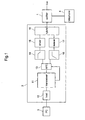
- Fig. 1 illustrates a schematic configuration of a communication system of an ATU-R side, to which the present invention is applied.
- a public phone line or a similar phone line hereafter referred to as line
- user terminal 3 is connected to ADSL modem apparatus 2.
- splitter 1 is necessary.
- splitter 1 is not needed. It is also possible to have a configuration where user terminal 3 internally installs ADSL modem apparatus 2.
- ADSL modem apparatus 2 includes transceiver 11 that executes ADSL communication, and host 12 that controls the entire operation including the one of transceiver 11.
- transceiver 11 that executes ADSL communication
- host 12 that controls the entire operation including the one of transceiver 11.
- units are configured with an analog circuit via analog front end (hereafter referred to as AFE) 13.
- AFE analog front end
- Driver 15 is connected to a DA converter of AFE 13 via analog filter 14, so that an analog signal amplified by driver 15 is transmitted to the line via hybrid 16.
- the analog signal transmitted from the line is received by receiver 17 via hybrid 16, and then input into an AD converter of AFE 13 via analog filter 18.
- AFE 13 When sampling data is output from the AD converter, AFE 13 outputs the data to transceiver 11.
- Fig. 2 is a functional block diagram illustrating transceiver 11.
- Processor 20 has functions to execute handshake and initialization sequences and to control communication during data transmission (SHOWTIME).
- the transmission side of transceiver 11 includes Reed-Solomon encoder 21 that adds a redundancy bit for checking error, interleave unit 22 that sorts data to enable a burst error correction during Reed-Solomon decoding, trellis encoder 23 that performs data convolution from a trellis encoding, tone ordering unit 24 that lays out a bit number for each carrier, constellation encoder 25 that allocates phase of the transmission data on constellation coordinates, and IFFT unit 26 that performs an Inverse Fast Fourier Transform (hereafter referred to as IFFT) on data after the constellation encoding process.
- IFFT Inverse Fast Fourier Transform
- the reception process side of transceiver 11 includes FFT unit 27 that performs a Fast Fourier Transform (hereafter referred to as FFT) on sampling data of the received signal, constellation decoder/FEQ unit 28 that decodes data from constellation data of the FFT output signal and corrects a phase on the constellation coordinates, tone de-ordering unit 29 that restores data assigned to each carrier after tone ordering process at the transmission side, Viterbi decoder 30 that performs Viterbi decoding on the received data, de-interleave unit 31 that restores data being rearranged by the transmission side, and Reed-Solomon decoder 32 that deletes the redundancy bit added by the transmission side.
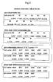
- RAM 33 is a work area of processor 20, which will be used for executing handshake and initialization sequences. Also, RAM 33 stores an advance compensation table shown in Figs. 3 and 4. Transceiver 11 is connected to host 12 via host interface (I/F) 34.
- the advance compensation data (gain compensation data and phase angle compensation data), prepared for a situation where the distance between ATU-C and ATU-R is around 1 km, is set for each index number.
- gain compensation data and phase angle compensation data are set in order to compensate the amplitude attenuation and phase angle shift respectively, at a point where transmission data of gain 1.0 and phase angle 0 (radian) has been transmitted 1 km.
- the advance compensation table shown in Fig. 4 sets the gain compensation data and phase angle compensation data, prepared for a situation where the distance between ATU-C and ATU-R is around 5 km.
- gain compensation data and phase angle compensation data is set in order to compensate the amplitude attenuation and phase angle shift respectively, at a point where transmission data of gain 1.0 and phase angle 0 (radian) has been transmitted 5 km.
- An ADSL modem apparatus of the center side is connected to ADSL modem apparatus 2 via a metallic cable.
- the ADSL modem apparatus of the center side has the same configuration as ADSL modem apparatus 2.
- telephone 4 does not exist.
- processor 20 performs an advance compensation process by retrieving the gain compensation data and phase angle compensation data from the advance compensation table, and multiplying the transmission data by the retrieved data.
- G.dmt positions 256 sub-carriers in 4.3125 kHz intervals.
- the first 26 sub-carriers, starting from the lowest frequency, are used for the upstream line, and the other 233 sub-carriers are used for the downstream line.
- the frequency band of 25 kHz to 1.1 MHz is used. Therefore, the remaining 7 sub-carriers that are in the frequency band below 25kHz are not used.
- the amplitude attenuation rate (G) and phase delay ( ⁇ ) may vary.
- Fig. 5 illustrates amplitude attenuation and phase angle shift for individual 256 sub-carriers. Each sub-carrier has an index number starting from the one having the lowest frequency. "#" represents an index.
- Fig. 5 illustrates a result of a simulation when the distance between ATU-C and ATU-R is set at 1 km. As shown in Fig. 5, as the index number (i.e., higher the frequency) becomes high, both the amplitude attenuation amount and the phase angle shift become larger.
- Fig. 6 illustrates a result of a simulation when the distance between ATU-C and ATU-R is set at 5 km. Compared to the 1 km distance between ATU-C and ATU-R, the amounts of amplitude attenuation and phase angle shift are different.
- the reception data when the amplitude of the transmission data is increased for the amplitude attenuation amount and the phase of the transmission data is rotated in the reverse direction for the phase delay in advance, the reception data, after amplitude attenuation and phase angle shift, should have the amplitude and phase angle data identical with the original data prior to the advance compensation.
- numerical formula (2) by multiplying both sides of numerical formula (1) by inverse matrix of G (amplitude attenuation at the line) and of determinant (illustrating phase angle shift " ⁇ "), transmission data (x0, y0) can be obtained.
- the data has the amplitude increased by the amplitude attenuation amount, and the phase is rotated in the reverse direction by the phase delay.
- the reception data (x1, y1), shown in the right side of the numerical formula (2) is a reception data at 0 km distance, having a gain of 1.0 and a phase angle shift of 0. According to the distance, each sub-carrier has different amplitude attenuation "G” and phase angle shift " ⁇ ".
- the transmission data is multiplied by "G” (gain compensation data) and " ⁇ " (phase angle compensation data).
- G gain compensation data
- ⁇ phase angle compensation data
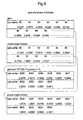
- Fig. 7 illustrates the amplitude attenuation and phase delay of the reception data in sub-carrier unit, when the distance between ATU-C and ATU-R is 1 km.
- Fig. 8 illustrates the amplitude attenuation and phase delay of the reception data, when the distance is changed to 5 km.
- amplitude attenuation (G) and phase angle shift ( ⁇ ) of the reception data can be obtained, as simulation values, for each sub-carrier (#).
- the advance compensation table of Fig. 3 is generated by multiplying the amplitude attenuation (G) and phase angle shift ( ⁇ ) (which are calculated for each sub-carrier), from the simulation values of Fig.
- the advance compensation table of Fig. 4 is generated by multiplying the amplitude attenuation (G) and phase angle shift ( ⁇ ) (which are calculated for each sub-carrier), from the simulation values of Fig. 8, by the reception data at distance 0 km (gain 1.0 and phase angle shift 0).
- ATU-C and ATU-R perform a handshake sequence based on G.994.1 in order to select a mode.
- G.dmt is selected as the mode for the initialization sequence.
- ATU-C uses indexes #64 and #48 to transmit C-PILOT signal or C-PILOT 1A signal.
- ATU-R upon starting the initialization sequence and detecting the signal energy at indexes #64 and #48, performs a hyperframe synchronization process based on the PILOT signal. Upon establishing the hyperframe synchronization, ATU-R transmits a R-REVERB1 signal.
- ATU-R performs the multiplication on the R-REVERB 1 signal, by gain compensation data and phase angle compensation data, in order to convert the signal into transmission data that has advance gain compensation and phase angle compensation.
- the handshake and initialization sequences are initiated when processor 20, having captured an FFT output from FFT unit 27, inputs transmission data into IFFT unit 26.
- the advance compensation table of Fig. 3 is used.
- Processor 20 generates a R-REVERB 1 signal for each sub-carrier (26 total), and multiplies each R-REVERB 1 signal by gain compensation data and phase angel compensation data corresponding to the index number.
- R-REVERB 1 signal has advance compensation per index unit.
- the R-REVERB1 signal after having the advance compensation has the reverse Fourier conversion by IFFT unit 26, and is converted into an analog signal by AFE 13. Then, the R-REVERB 1 signal arrives at ATU-C via the line. When passing through the line, the R-REVERB 1 signal becomes affected by the amplitude attenuation and phase angel shift. However, because of the advance compensation, the transmission data shows the original amplitude and phase angle, after being affected by the amplitude attenuation and phase angle shift.
- processor 20 of ATU-C can obtain the R-REVERB1 signal having no (or a minimum degree of) amplitude attenuation and phase angle shift. Because processor 20 can obtain the R-REVERB 1 signal having no or minimum distortion, it is possible to prevent error, which makes it impossible to capture the signal. Similarly, it is possible to establish symbol synchronization with the remote side.
- the ATU-C upon detecting the R-REVERB 1 signal, transmits a C-REVERB 1 signal to the remote side.
- ATU-C performs the same advance compensation process on the C-REVERB 1 signal as the remote side.
- processor 20 generates a C-REVERB1 signal for each sub-carrier (256 max.), and multiplies each C-REVERB 1 signal by the gain compensation data and phase angle compensation data for the corresponding index number.
- the C-REVERB1 signal after being advance-compensated, has the reverse Fourier conversion by IFFT unit 26, and is converted into an analog signal by AFE 13 prior to its transmission. Then, the C-REVERB 1 signal arrives at ATU-R via the line.
- the C-REVERB 1 signal When passing through the line, the C-REVERB 1 signal becomes affected by the amplitude attenuation and phase angel shift. However, because of the advance compensation, the transmission data shows the original amplitude and phase angle, after being affected by the amplitude attenuation and phase angle shift. Accordingly, processor 20 of ATU-R can obtain the C-REVERB 1 signal having no or minimum distortion, thereby making it possible to securely capture the signal prior to establishing the symbol synchronization. Then, the symbol synchronization can be securely established based on the captured C-REVERB signal, without causing errors.
- the advance compensation table of Fig. 4 is used.
- the advance compensation process at ATU-C and ATU-R is similar to the case that uses the advance compensation table of Fig. 3.
- the advance compensation in accordance with the distance is needed.
- the advance compensation table of Fig. 4 it is possible to perform advance compensation according to the amplitude attenuation and phase angle shift received in the real line (5 km).
- Fig. 9 illustrates the handshake sequence and the first half of the initialization sequence.
- complex operation circuit 35 can be set in the input section of IFFT unit 26, so that complex operation circuit 35 performs the multiplication of the gain compensation data and phase angle compensation data.
- the gain compensation data and phase angle compensation data (used by complex operation circuit 35 for the multiplication) is set as complex numbers in accordance with the C-REVERB 1 signal and R-REVERB 1 signal.
- gain compensation data and phase angel compensation data of different distances can be used as the complex multiplication coefficients.
- the above data in the complex operation circuit can be rewritten, by the CPU, according to different communication distances such as 1 km, 2km, and 5km.
- the CPU can, by confirming the distance between ATU-C and ATU-R, set the appropriate gain compensation data and phase angel compensation data as the complex multiplication coefficients in the complex operation circuit.
- complex operation circuit 35 can have the data in advance for each distance in a parallel configuration. In this case, the predetermined data can be obtained by switching the complex operation circuit for each distance.
- the transmission data has the advance compensation process
- the data is processed by complex operation circuit 35.
- the flow of the signal needs to be controlled so that the transmission data is input to IFFT unit 26, without being processed by complex operation circuit 35.
- the above illustration used an example where the advance compensation is performed by multiplying only C-REVERB1 signal and R-REVERB1 signal by the gain compensation data and phase angle compensation data.
- a similar advance compensation process can be performed on an arbitrary signal or all signals during the handshake and initialization sequences.
- the transmission data is first converted into constellation data by constellation encoder 25, and is input to IFFT unit 26. Because of a long distance between ATU-C and ATU-R, when there is a large attenuation and phase angle shift of the transmission data transmitted during the SHOWTIME, it is effective to perform the advance compensation on all of the transmission data, during the SHOWTIME, by multiplying the gain compensation data and phase angle compensation data. In other cases, the data should be input to IFFT unit 26 without the advance compensation.
- complex operation circuit 35 When the advance compensation process is performed on the transmission data during the SHOWTIME, complex operation circuit 35 is positioned before IFFT unit 26.
- constellation data output from constellation encoder 25 i.e., transmission data illustrated with complex number
- the transmission data is multiplied by the gain compensation data and phase angle compensation data for each sub-carrier.
- the advance-compensated transmission data on its amplitude and phase angle, is input to IFFT unit 26, processed by the reverse Fourier conversion, and transmitted to the line.
- the gain compensation data and phase angle compensation data in complex operation circuit 35 are set at an appropriate data according to the distance between ATU-C and ATU-R.
- ADSL modem used an ADSL modem
- present invention can be applied to other xDSL modems that are employed by other types of DSLs.
Landscapes
- Engineering & Computer Science (AREA)
- Signal Processing (AREA)
- Life Sciences & Earth Sciences (AREA)
- Environmental Sciences (AREA)
- Computer Networks & Wireless Communication (AREA)
- Marine Sciences & Fisheries (AREA)
- Animal Husbandry (AREA)
- Biodiversity & Conservation Biology (AREA)
- Telephonic Communication Services (AREA)
- Digital Transmission Methods That Use Modulated Carrier Waves (AREA)
- Cable Transmission Systems, Equalization Of Radio And Reduction Of Echo (AREA)
Applications Claiming Priority (2)
| Application Number | Priority Date | Filing Date | Title |
|---|---|---|---|
| JP2003299108 | 2003-08-22 | ||
| JP2003299108A JP2005072897A (ja) | 2003-08-22 | 2003-08-22 | Dslモデム装置及び通信制御方法 |
Publications (2)
| Publication Number | Publication Date |
|---|---|
| EP1509017A2 true EP1509017A2 (de) | 2005-02-23 |
| EP1509017A3 EP1509017A3 (de) | 2005-03-02 |
Family
ID=34056272
Family Applications (1)
| Application Number | Title | Priority Date | Filing Date |
|---|---|---|---|
| EP04012339A Withdrawn EP1509017A3 (de) | 2003-08-22 | 2004-05-25 | DSL Modem und Kommunikationssteuerungsverfahren |
Country Status (4)
| Country | Link |
|---|---|
| US (1) | US20050041730A1 (de) |
| EP (1) | EP1509017A3 (de) |
| JP (1) | JP2005072897A (de) |
| KR (1) | KR20050020926A (de) |
Families Citing this family (4)
| Publication number | Priority date | Publication date | Assignee | Title |
|---|---|---|---|---|
| KR100732087B1 (ko) * | 2005-10-13 | 2007-06-27 | 엘지노텔 주식회사 | 키폰 시스템의 거리별 통화감도 조정 방법 |
| KR100765322B1 (ko) * | 2005-12-08 | 2007-10-09 | 삼성전자주식회사 | 가변 정합이 가능한 아날로그 트렁크 정합장치 및 그제어방법 |
| US8111716B2 (en) * | 2008-02-15 | 2012-02-07 | Ibiquity Digital Corporation | Method and apparatus for formatting data signals in a digital audio broadcasting system |
| CN114461973B (zh) * | 2021-12-23 | 2024-07-02 | 北京四方继保工程技术有限公司 | 一种频率偏移时dft计算相角的补偿方法与系统 |
Family Cites Families (10)
| Publication number | Priority date | Publication date | Assignee | Title |
|---|---|---|---|---|
| US6219378B1 (en) * | 1997-09-17 | 2001-04-17 | Texas Instruments Incorporated | Digital subscriber line modem initialization |
| DK1021901T3 (da) * | 1997-10-10 | 2010-03-08 | Daphimo Co B V Llc | Splitterløst multibærermodem |
| US20030026282A1 (en) * | 1998-01-16 | 2003-02-06 | Aware, Inc. | Splitterless multicarrier modem |
| EP1021901B1 (de) * | 1997-10-10 | 2009-11-25 | Daphimo Co. B.V., LLC | Teilerloses mehrträgermodem |
| US7406261B2 (en) * | 1999-11-02 | 2008-07-29 | Lot 41 Acquisition Foundation, Llc | Unified multi-carrier framework for multiple-access technologies |
| SE516879C2 (sv) * | 1999-11-23 | 2002-03-19 | Ericsson Telefon Ab L M | Signalnivåjusteringsanordning |
| ATE250305T1 (de) * | 2000-11-20 | 2003-10-15 | Sony Int Europe Gmbh | Ofdm-system mit sender-antennendiversity und vorentzerrung |
| US6665021B2 (en) * | 2001-02-05 | 2003-12-16 | Conexant Systems, Inc. | System and process for filtering single tone signals |
| JP2004072269A (ja) * | 2002-08-02 | 2004-03-04 | Panasonic Communications Co Ltd | Adslモデム装置及びその通信方法 |
| US7280612B2 (en) * | 2003-07-25 | 2007-10-09 | Zarbana Digital Fund Llc | Digital branch calibrator for an RF transmitter |
-
2003
- 2003-08-22 JP JP2003299108A patent/JP2005072897A/ja active Pending
-
2004
- 2004-02-20 US US10/781,690 patent/US20050041730A1/en not_active Abandoned
- 2004-04-30 KR KR1020040030658A patent/KR20050020926A/ko not_active Ceased
- 2004-05-25 EP EP04012339A patent/EP1509017A3/de not_active Withdrawn
Also Published As
| Publication number | Publication date |
|---|---|
| KR20050020926A (ko) | 2005-03-04 |
| US20050041730A1 (en) | 2005-02-24 |
| JP2005072897A (ja) | 2005-03-17 |
| EP1509017A3 (de) | 2005-03-02 |
Similar Documents
| Publication | Publication Date | Title |
|---|---|---|
| JP3692044B2 (ja) | Tcm−isdnクロストーク環境下におけるadslトランシーバのための等化器訓練 | |
| US6718019B1 (en) | Method and apparatus for wireline characterization | |
| JP3969406B2 (ja) | マルチスタンダードdmtdsl伝送システム用モデム | |
| EP3393076B1 (de) | Verfahren und vorrichtung zur erhöhung der robustheit eines differenzierten kommunikationskanals in einem mehrtonsendeempfänger | |
| US8325825B2 (en) | Method and apparatus for optimizing dynamic range in DMT modems | |
| EP1509017A2 (de) | DSL Modem und Kommunikationssteuerungsverfahren | |
| US6690666B1 (en) | Packet modulation for DSL | |
| US7305001B2 (en) | ADSL modem apparatus and ADSL modem communication method | |
| KR101352049B1 (ko) | 광대역 무선통신 시스템에서 상향링크 전력제어를 위한송신장치 및 방법 | |
| EP1508976B1 (de) | DSL-Modem und Verfahren zur Steuerung der Kommunikation | |
| EP1367809B1 (de) | DSL-Initialisierung mit Benutzung vom Verschachtelungsspeicher | |
| EP1507397A2 (de) | DSL-Modemvorrichtung und Übertragungssteuerungsverfahren | |
| US7852869B2 (en) | Method and apparatus for the transmission of data | |
| US20060133467A1 (en) | Method and apparatus for generating a periodic training signal | |
| EP1367791A2 (de) | Vertstärkungsreglung für ein Mehrträgermodem | |
| EP1503568A2 (de) | ADSL-Modemvorrichtung und Übertragungsverfahren | |
| JP2003517249A (ja) | 離散マルチトーン変調による2重データ伝送中の信号エコーを補償するための方法および装置 | |
| EP1367792A2 (de) | Einrichtung für ein DSL-Modem sowie Empfangsverfahren zur DSL-Vermittlung | |
| JP2005236382A (ja) | Dslモデム装置及びdsl通信制御方法 | |
| US20050025086A1 (en) | ADSL modem apparatus and communication method thereof | |
| JP2004072267A (ja) | Adslモデム装置及びその通信方法 | |
| JP2005236381A (ja) | Dslモデム装置及びdsl通信制御方法 | |
| JP2002501712A (ja) | 複数の周波数帯域によるデータ伝送方法 |
Legal Events
| Date | Code | Title | Description |
|---|---|---|---|
| PUAI | Public reference made under article 153(3) epc to a published international application that has entered the european phase |
Free format text: ORIGINAL CODE: 0009012 |
|
| PUAL | Search report despatched |
Free format text: ORIGINAL CODE: 0009013 |
|
| 17P | Request for examination filed |
Effective date: 20040525 |
|
| AK | Designated contracting states |
Kind code of ref document: A2 Designated state(s): AT BE BG CH CY CZ DE DK EE ES FI FR GB GR HU IE IT LI LU MC NL PL PT RO SE SI SK TR |
|
| AX | Request for extension of the european patent |
Extension state: AL HR LT LV MK |
|
| AK | Designated contracting states |
Kind code of ref document: A3 Designated state(s): AT BE BG CH CY CZ DE DK EE ES FI FR GB GR HU IE IT LI LU MC NL PL PT RO SE SI SK TR |
|
| AX | Request for extension of the european patent |
Extension state: AL HR LT LV MK |
|
| AKX | Designation fees paid |
Designated state(s): DE FR GB |
|
| STAA | Information on the status of an ep patent application or granted ep patent |
Free format text: STATUS: THE APPLICATION HAS BEEN WITHDRAWN |
|
| 18W | Application withdrawn |
Effective date: 20060808 |