EP1509080B1 - Vorrichtung zum auf- und abwickeln von einem vorfach einer angelleine - Google Patents
Vorrichtung zum auf- und abwickeln von einem vorfach einer angelleine Download PDFInfo
- Publication number
- EP1509080B1 EP1509080B1 EP02798377A EP02798377A EP1509080B1 EP 1509080 B1 EP1509080 B1 EP 1509080B1 EP 02798377 A EP02798377 A EP 02798377A EP 02798377 A EP02798377 A EP 02798377A EP 1509080 B1 EP1509080 B1 EP 1509080B1
- Authority
- EP
- European Patent Office
- Prior art keywords
- line
- housing
- bait
- fishing
- cylinder
- Prior art date
- Legal status (The legal status is an assumption and is not a legal conclusion. Google has not performed a legal analysis and makes no representation as to the accuracy of the status listed.)
- Expired - Lifetime
Links
- 238000004804 winding Methods 0.000 title claims abstract description 18
- XLYOFNOQVPJJNP-UHFFFAOYSA-N water Substances O XLYOFNOQVPJJNP-UHFFFAOYSA-N 0.000 claims abstract description 24
- 239000000463 material Substances 0.000 claims abstract description 9
- 239000013505 freshwater Substances 0.000 claims abstract description 3
- 230000033001 locomotion Effects 0.000 claims description 13
- 239000002184 metal Substances 0.000 claims description 12
- 238000005452 bending Methods 0.000 claims 1
- 229910052755 nonmetal Inorganic materials 0.000 claims 1
- 241000251468 Actinopterygii Species 0.000 abstract description 18
- 230000009747 swallowing Effects 0.000 abstract description 3
- 230000007246 mechanism Effects 0.000 description 17
- 230000000694 effects Effects 0.000 description 8
- 230000000284 resting effect Effects 0.000 description 3
- 238000010276 construction Methods 0.000 description 2
- 230000007423 decrease Effects 0.000 description 2
- 230000005489 elastic deformation Effects 0.000 description 2
- 238000004519 manufacturing process Methods 0.000 description 2
- 239000007769 metal material Substances 0.000 description 2
- 230000007723 transport mechanism Effects 0.000 description 2
- 239000002982 water resistant material Substances 0.000 description 2
- 244000182067 Fraxinus ornus Species 0.000 description 1
- 241000167880 Hirundinidae Species 0.000 description 1
- 235000014676 Phragmites communis Nutrition 0.000 description 1
- 229910000831 Steel Inorganic materials 0.000 description 1
- 230000008468 bone growth Effects 0.000 description 1
- 230000007797 corrosion Effects 0.000 description 1
- 238000005260 corrosion Methods 0.000 description 1
- 230000008034 disappearance Effects 0.000 description 1
- 238000000034 method Methods 0.000 description 1
- 238000010422 painting Methods 0.000 description 1
- 238000005381 potential energy Methods 0.000 description 1
- 239000010935 stainless steel Substances 0.000 description 1
- 239000010959 steel Substances 0.000 description 1
- 230000009466 transformation Effects 0.000 description 1
- 239000012780 transparent material Substances 0.000 description 1
Images

Classifications
-
- A—HUMAN NECESSITIES
- A01—AGRICULTURE; FORESTRY; ANIMAL HUSBANDRY; HUNTING; TRAPPING; FISHING
- A01K—ANIMAL HUSBANDRY; AVICULTURE; APICULTURE; PISCICULTURE; FISHING; REARING OR BREEDING ANIMALS, NOT OTHERWISE PROVIDED FOR; NEW BREEDS OF ANIMALS
- A01K91/00—Lines
- A01K91/03—Connecting devices
- A01K91/04—Connecting devices for connecting lines to hooks or lures
-
- A—HUMAN NECESSITIES
- A01—AGRICULTURE; FORESTRY; ANIMAL HUSBANDRY; HUNTING; TRAPPING; FISHING
- A01K—ANIMAL HUSBANDRY; AVICULTURE; APICULTURE; PISCICULTURE; FISHING; REARING OR BREEDING ANIMALS, NOT OTHERWISE PROVIDED FOR; NEW BREEDS OF ANIMALS
- A01K83/00—Fish-hooks
- A01K83/06—Devices for holding bait on hooks
-
- A—HUMAN NECESSITIES
- A01—AGRICULTURE; FORESTRY; ANIMAL HUSBANDRY; HUNTING; TRAPPING; FISHING
- A01K—ANIMAL HUSBANDRY; AVICULTURE; APICULTURE; PISCICULTURE; FISHING; REARING OR BREEDING ANIMALS, NOT OTHERWISE PROVIDED FOR; NEW BREEDS OF ANIMALS
- A01K85/00—Artificial bait for fishing
- A01K85/16—Artificial bait for fishing with other than flat, or substantially flat, undulating bodies, e.g. plugs
Definitions
- the subject of invention is the device for winding and unwinding the lower part of fishing line, used as a bait or insert for natural and artificial fishing baits for fishing predatory freshwater and sea fish.
- a similar device is already known by US-A-5 029 410.
- the invention belongs to the fields of technique, marked as follows:
- Predatory fishes belong to the range of largest and strongest fishes for which there is necessary the equipment of special make, in order to attract fish of prey and to hold them on a hook till drawing them out of water: Predatory fish have in their jaws bone growths in form of teeth for cutting and tearing the catches. Therefore these lower parts of line resp. casts., represent one of most loaded part of fishing equipment for fishing predatory fish, because they are subjected to large tensile and gliding strains. Lines in general should be made of transparent materials, invisible in water, so that baits on lines would leave as natural as possible impression.
- pre-lines are made of metal, mostly steel wires with high mechanical and corrosion-resistant characteristics. The problem of visibility of pre-lines in water is solved by reducing their thickness which decreases their mechanical characteristics and painting, which make them more expensive as products.
- an artificial bait with mechanism for setting in motion parts of bait imitating fish fins or frog legs The mechanism consists of reel, on which there is winded the lower part of a line and which is fixedly supported on the rotating axis of the blade coil spring of the mechanism for transport and transformation of rotational motion of the axis into alternate motion of bait limbs, spring housing and transport mechanism, as well as the limbs of the bait themselves. All parts of the mechanism, except limbs, are arranged in the bait.
- the motion of bait limbs is made by pulling the line out of the bait, whereby the line is unwinding from the reel and the blade coil spring is strained.
- the line is winding on the reel by menas of blade coil spring, which inner movable part is fixed to the rotation axis and the external fixed end to the fixed housing of the spring and transport mechanism.
- the described mechanism has been exclusively intended for setting in motion parts of artificial bait, imitating limbs of natural bait when the bait is moving through the water.
- the lower part of line winding and unwinding on the reel is not the subject of patent protection.
- the device for winding and unwinding the lower part of the fishing line consists of two-piece shell-like housing in which the spring mechanism is arranged, for pulling in the lower, reinforced line into the housing or pulling the lower, reinforced part of the line out of the housing.
- the spring mechanism consists of the hollow cylinder supported on the fixed axis, fastened to one half of the housing and blade coil spring put in the hollow in the cylinder.
- the internal fixed end of the spring is fastened to the fixex axis of the cylinder and its movable external end to the ring of the cylinder.
- the lower part of the line When the bait with the device is in a passive state of resting or moving through the water when water resistance force is smaller than the pretension of the spring, the lower part of the line remains completely wound round the ring of the cylinder. The ring of the external end of line is then leant to the external part of the opening for line on the housing of the device because of effect of pretension force in the spring. In this way the whole lower part of the line is invisible, because it is wound in relatively small housing of a device that makes a part of the bait which effect of attracting fish is not disturbed by the visible lower part of a line.
- the device for winding and unwinding of the lower part of a line (cast) for fishing belongs to baits or type of device for holding baits on a hook, that are inserted in natural or artificial baits or to which natural or artificial baits are fastened.
- the device in form of insert represeents the universal part, applicable for all types of baits fastened to the lower part of lines with a high tensile and gliding strenth that are invisible in the stage of attracting fish.
- the set aim of finding the solution for invisibility in water of a lower, reinforced, nontransparent metal part of the line in a stage of attracting fish and effective and resistant to high tensile and gliding stresses in stages of swallowing, tearing and pulling the bait is achieved in the whole, by which the total exploitability of fishing equipment is encreased.
- the solution according to the invention solved the problem of effectiveness of bait attractivenes and effectiveness of the lower part of a line, whereas by the solution described in the mentioned family of patent documents there is solved only the problem of effectiveness of bait attractiveness.
- the solution according to the invention in relation to the solution described in the mentioned family of patent documents, the set aim of increasing the effectiveness of bait attractiveness is achieved in essentially different way, with essentially different construction and with essentially differentl effects of these solutions.
- Attractiveness of the bait in the solution described in the mentioned patent family is solved by setting in motion limbs of a bait only when it is moving through the water, whereas the same problem in the described invention is solved by pulling the lower visible part of a line into the bait when the bait is either resting in water or moving through the water.
- the solution described in the mentioned family of patent documents consists of a device consisting of complex multupart spring mechanism in which the reel and spring are separated and in which there is arranged the movable internal end of a spring and the axis fastened to the external end of a spring. Fastening of the internal end of a line and its conducting on the strake of the reel is not clearly defined.
- the mechanism for transfer of rotation motion of the spring mechanism axis to the oscillating motion of bait limbs is a complex and expensive mechanism.
- the spring mechanism of the solution according to the invention consists of the cylinder and spring arranged in the cylinder.
- the fixed internal end of a spring is fastened to the fixed axis and the movable external end of the spring directly to the cylinder strake. Fastening of the internal end of line and its conducting on the strake of a reel is clearly defined and does not allow the line getting stuck and overstressing the spring outside the field of elastic deformation.
- the lower line part may have significantly bigger cross-section than the cast and could be made of materials, visible in water, resistant to large tenside and gliding stresses as e.g. metal materials, whereas in the solution described in the mentioned family of patent documents, the cast is not the matter of patent protection.
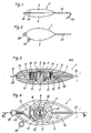
- a device 1 for winding and unwinding the lower part of fishing line (cast) shown on figures 1 to 7, consists of housing, spring mechanism, lower line part (cast) and parts for acceptance of baits and hooks.
- the housing has a form of extended shell consisting of the lower 2 and upper part 3, which external mantles are speculary symmetrical and which are decomposably connected.
- the connection of the lower part 2 of the housing and the upper part 3 of the housing is made as a tight seat connection of internal overhangs 4 of one part entering in recesses in the other part of a housing.
- a cylindrical hollow 6 for arrangement of a spring mechanism.
- the axis 7 In the middle of the hollow 6 there is the axis 7, which lower part is decomposably connected with the lower part 2 of the housing and which free upper end enters in the recess 8 in the upper part 3 of the housing.
- the housing In the upper part of the axis 7 there is the slot 9 which depth is larger than the half of the lenght of the axis 7.
- the axial channel 10 In the front part of the housing there is the axial channel 10 by which the hollow 6 is connected with the outlet opening 11.
- the rare part of the housing there is axial bore hole 12 with vertical hole 13 in the lower part 2 of the housing.
- the housing is made of water resistant materials as polymeric materials.
- the spring mechanism consisting of the hollow cylinder 14 rotationally bedded on the axis 15 turned to the upper part 3 of the housing.
- the internal, fixed end 16 of the spring 15 is inserted in the 9 on the upper part of the axis 7 and its external, movable end 17 is wound round the tooth 18 on the strake of cylinder 14 in the opposite direction from the direction of the spring curve 15 and tightened on the internal area 19 of the cylinder strake 14.
- the spring 15 In the initial position, the spring 15 is wound in the way, that the external 27 of the line 21 which is through the ring 28 leaning against the opening 11 of the housing is under the pretension force.
- the pretension force of the spring 15 should be higher than the weight of the device with the bait in the water and higher than water resistance force to the motion of device with bait through the water. Under such circumstances, the lower part (cast) of line 21 shall in all using circumstances be pulled in the device and invisible for the catch.
- the lower part of a line 21 shall be completely unwound from the cylinder 14, to which it remains connected through the sleeve 24 by the internal end 22.
- the spring 15 in which the force is increasing shall wind up.
- the work deflection of the spring 15 representing the total deflection of the spring 15, reduced for the pretension deflection, to be larger than wound length of the lower part of line 21, in order of correct functioning of the spring 15 in the field of elastic deformation.
- Parts of spring mechanism and the lower part of line 21 and belonging part should also be made of water resistant materials as polymeric materials and corossion resistant metal materials.
- cylinder 14 it would be the best to manufacture it of water resistant polymeric materials, whereas the blade coil spring 15, lower part of the line (21), stirrup 26 and ring 28, should be made of corrosion resistant steel materials with high tensile and gliding strength.
- the metal stirrup 29 In the front part of the device housing there is fastened the metal stirrup 29, to which by short lines 30 there is connected one or more metal hooks 31.
- the bearing 32 of baids in the form of metal rod In the axial bore hole 21 of the housing there is inserted the bearing 32 of baids in the form of metal rod, which internal end 33 is bent under right angle and inserted in vertical hole 13 in the lower part 2 of the housing.
- the external end 34 of the bearing 32 is bent under the angle exceeding 90° in the hook for baits.
- Described device for winding and unwinding the lower part of fishing line may be used as independent artificial bait, as the insert applicable to all kinds of artificial or natural baits.
- the device 1 may be used as independent artificial bait.
- the housing of the device 1 should be shaped in a way, that by its external appearance it imitates one of natural baits.
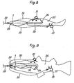
- the device 1 may be used as a model of artificial or natural bait 35, as it is shown on Fig. 8.
- the artificial or natural bait 35 is pulled on the support 32 up to the housing of the device.
- the bait 35 is connected to the device 1, that is over the ring 28 tied to the upper part 37 of the line, tied to the fishing rod.
- the device 1 may be used as the insert in artificial or natural bait 36, as it is shown on Fig. 9. Through the mouth of the bait 36 there is inserted the whole device 1, which is by the hooked end 34 of the support 32 and hooks 31, fastened to the bait 36. The device 1 is over the the ring 28 tied to the upper part 37 of the line, tied to the fishing rod.
Landscapes
- Life Sciences & Earth Sciences (AREA)
- Environmental Sciences (AREA)
- Animal Husbandry (AREA)
- Biodiversity & Conservation Biology (AREA)
- Marine Sciences & Fisheries (AREA)
- Control Of El Displays (AREA)
- Superconductors And Manufacturing Methods Therefor (AREA)
- Air Conditioning Control Device (AREA)
Claims (4)
- Einrichtung zum Auf- und Abwinkeln des unteren Teils einer Angelschnur, dadurch gekennzeichnet, daß die Vorrichtung (1) aus einem zweiteiligen Gehäuse in der Form einer verlängerten Muschel besteht, bestehend aus den unteren (2) und oberen Teil (3), dessen externe bzw. Außenmäntel (3) spiegelsymmetrisch sind und welche zerlegbar durch eine Verbindung mit dichtem Sitz von inneren Vorsprüngen (4) eines Teils verbunden sind, welche in Vertiefungen bzw. Ausnehmungen (5) in dem anderen Teil eines Gehäuses eintreten, in dessen breitestem Teil sich ein zylindrischer Hohlraum (6) mit der Achse (7) befindet, wobei das untere Teil zerlegbar mit dem unteren Teil (2) des Gehäuses verbunden ist und in dessen freiem, oberem Ende, welches in die Vertiefung (8) in dem oberen Teil (3) des Gehäuses eintritt, sich ein Schlitz (9) befindet, dessen Tiefe größer als die Hälfte der Länge der Achse (7) ist, daß sich in dem vorderen Teil des Gehäuses der axiale Kanal (10) befindet, durch welchen der Hohlraum (6) mit der Auslaßöffnung (11) verbunden ist, und sich in dem verbleibenden Teil des Gehäuses ein axiales Bohrungsloch (12) mit einem vertikalen Loch (13) befindet, welches in dem unteren Teil (2) des Gehäuses hergestellt ist, in welchem zylindrischen Hohlraum (6) in Drehrichtung an der Achse (7) der hohle Zylinder (14) eingebettet ist, in welchem Hohlraum, welcher zu dem oberen Teil des Gehäuses gewandt ist, die Spiralblatt- bzw. Schraubenfeder (15) angeordnet ist, deren festgelegtes Ende (16) in den Schlitz (9) an dem oberen Teil der Achse (7) eingesetzt ist und deren externes, bewegbares Ende (17) um den Zahn (18) auf dem Umfang des Zylinders (14) in der entgegengesetzten Richtung von der Richtung der Federkurve (15) gewickelt und auf dem inneren Bereich (19) des Zylinderumfangs (14) festgelegt ist, an welcher äußeren Oberfläche des Rings sich die Kurvenrille bzw. -nut befindet, in welcher das untere Teil der Schnur (21) gewickelt ist, deren inneres Ende (22) durch die radiale Öffnung (23) auf dem Ring des Zylinders (14) gezogen und um die Lagerhülse (24) in der Rille (25) gewickelt ist und durch den Bügel (26) an der Leine bzw. Schnur befestigt ist, und wobei das äußere Ende (27) der Schnur durch den Kanal (10) des Gehäuses gezogen bzw. hindurchgeführt und mit dem Ring (28) verbunden ist, welcher gegen die Öffnung (11) des Gehäuses anliegt, in dessen vorderem Teil der Metallbügel (29) angeordnet ist, mit welchem mit kurzen Schnüren (30) ein oder mehrere Metallhaken (31) verbunden ist bzw. sind, und wobei in das axiale Bohrungsloch (12) in dem rückwärtigen Teil des Gehäuses die Abstützung (32) von Ködern in Form von Metallstangen eingesetzt ist, deren inneres Ende (33) unter einem rechten Winkel gebogen ist und in das vertikale Loch (13) in dem unteren Teil (2) des Gehäuses eingesetzt ist und deren äußeres Ende (34) um den 90° überschreitenden Winkel in dem Haken für Köder gebogen ist.
- Einrichtung zum Auf- und Abwinkeln des unteren Teils einer Angelschnur nach Anspruch 1, dadurch gekennzeichnet, daß in einer Ausgangsposition, in welcher der Ring (28) gegen die Öffnung (11) des Gehäuses lehnt, das externe Ende (27) der Schnur (21) mit einer Zugkraft einer Vorspannfeder (15) beaufschlagt ist, welche für eine Vorspannablenkung komprimiert ist, welche höher als das Gewicht der Einrichtung mit einem Köder in dem Wasser und eine Wasserwiderstandskraft gegenüber der Bewegung der Einrichtung mit einem Köder durch das Wasser ist, und daß die Arbeitsablenkung bzw. -durchbiegung der Feder (19), welche die gesamte Ablenkung der Feder (15) repräsentiert, welche um die Vorspannablenkung reduziert ist, größer als die Länge des unteren Teils der Schnur (21) ist, welche in die gekrümmte Rille (20) auf dem Ring des Zylinders (14) gewickelt ist.
- Einrichtung zum Auf- und Abwinkeln des unteren Teils einer Angelschnur nach Anspruch 1 und 2, dadurch gekennzeichnet, daß das gesamte untere Teil der Schnur (21) mit dem inneren Ende (22) und äußeren Ende (27) aus einem wasserbeständigen, chemisch stabilen in Süßwasser und Seewasser, nicht transparenten oder transparenten, metallischen oder nicht-metallischen, sich biegenden Material hergestellt ist, dessen Dicke gleich der Dicke des oberen Teils der Schnur (37) oder verschieden von dieser ist, und daß eine Zug- und Scher- bzw. Gleitstärke bzw. -festigkeit des unteren Teils der Schnur (21) höher als die Zug- und Scherfestigkeit des oberen Teils der Schnur (21) ist.
- Einrichtung zum Auf- und Abwinkeln des unteren Teils einer Angelschnur nach Anspruch 1 bis 3, dadurch gekennzeichnet, daß die Vorrichtung (1) als ein unabhängiger, künstlicher Köder angewandt wird, welcher durch das äußere Aussehen des Gehäuses den natürlichen Köder imitiert oder als das Modell bzw. die Vorlage eines künstlichen oder natürlichen Köders (35) oder als ein Einsatz in dem künstlichen oder natürlichen Köder (36), welche über den Ring (28) an das obere Teil (37) der Schnur gebunden ist.
Applications Claiming Priority (3)
| Application Number | Priority Date | Filing Date | Title |
|---|---|---|---|
| HR20020190 | 2002-02-28 | ||
| HR20020190A HRP20020190B1 (en) | 2002-02-28 | 2002-02-28 | Device for winding and unwinding the lower part of fishing line |
| PCT/HR2002/000066 WO2003073844A1 (en) | 2002-02-28 | 2002-12-24 | Device for winding and unwinding the lower part of fishing line |
Publications (2)
| Publication Number | Publication Date |
|---|---|
| EP1509080A1 EP1509080A1 (de) | 2005-03-02 |
| EP1509080B1 true EP1509080B1 (de) | 2006-03-08 |
Family
ID=27772921
Family Applications (1)
| Application Number | Title | Priority Date | Filing Date |
|---|---|---|---|
| EP02798377A Expired - Lifetime EP1509080B1 (de) | 2002-02-28 | 2002-12-24 | Vorrichtung zum auf- und abwickeln von einem vorfach einer angelleine |
Country Status (10)
| Country | Link |
|---|---|
| US (1) | US7111426B2 (de) |
| EP (1) | EP1509080B1 (de) |
| AT (1) | ATE319305T1 (de) |
| AU (1) | AU2002363911A1 (de) |
| CA (1) | CA2505629A1 (de) |
| DE (1) | DE60209808T2 (de) |
| DK (1) | DK1509080T3 (de) |
| ES (1) | ES2260511T3 (de) |
| HR (1) | HRP20020190B1 (de) |
| WO (1) | WO2003073844A1 (de) |
Families Citing this family (6)
| Publication number | Priority date | Publication date | Assignee | Title |
|---|---|---|---|---|
| US8186097B2 (en) * | 2008-03-14 | 2012-05-29 | Ardent Outdoors, Inc. | Fish culling system |
| US20150107148A1 (en) * | 2010-11-22 | 2015-04-23 | Justice Tackle & Co.,LLC | Chambered Leader Lure |
| US9258986B2 (en) * | 2010-11-22 | 2016-02-16 | Justice Tackle & Co., Llc | Chambered leader lure |
| US10194646B2 (en) * | 2010-11-22 | 2019-02-05 | A Band Of Anglers, Inc. | Modular chambered leader fishing lure |
| JP7718972B2 (ja) * | 2021-11-26 | 2025-08-05 | 株式会社シマノ | ルアー |
| US12599121B2 (en) * | 2023-03-17 | 2026-04-14 | Juka Innovations Corporation | Fishing line to lure connector |
Family Cites Families (8)
| Publication number | Priority date | Publication date | Assignee | Title |
|---|---|---|---|---|
| US1758160A (en) * | 1929-01-29 | 1930-05-13 | Ammie L Lee | Fishing lure |
| US2950559A (en) * | 1958-10-24 | 1960-08-30 | William O Nelson | Fishing lure |
| US4068401A (en) * | 1975-08-19 | 1978-01-17 | Masudaya Toy Company Limited | Self-powered toy animal |
| US5035075A (en) | 1984-03-30 | 1991-07-30 | Powerpak Lures, Inc. | Fishing lure |
| US4831767A (en) | 1984-03-30 | 1989-05-23 | Powerpak Lures, Inc. | Fishing lure |
| US4674223A (en) | 1984-03-30 | 1987-06-23 | Thornton-Denena Industries | Fishing lure |
| WO1988010067A1 (en) | 1987-06-22 | 1988-12-29 | Thornton-Denena Industries | Fishing lure |
| US5029410A (en) * | 1990-08-15 | 1991-07-09 | Anderson Donald L | Fishing lure |
-
2002
- 2002-02-28 HR HR20020190A patent/HRP20020190B1/xx not_active IP Right Cessation
- 2002-12-24 CA CA002505629A patent/CA2505629A1/en not_active Abandoned
- 2002-12-24 ES ES02798377T patent/ES2260511T3/es not_active Expired - Lifetime
- 2002-12-24 EP EP02798377A patent/EP1509080B1/de not_active Expired - Lifetime
- 2002-12-24 DK DK02798377T patent/DK1509080T3/da active
- 2002-12-24 DE DE60209808T patent/DE60209808T2/de not_active Expired - Lifetime
- 2002-12-24 AT AT02798377T patent/ATE319305T1/de not_active IP Right Cessation
- 2002-12-24 AU AU2002363911A patent/AU2002363911A1/en not_active Abandoned
- 2002-12-24 WO PCT/HR2002/000066 patent/WO2003073844A1/en not_active Ceased
-
2005
- 2005-01-05 US US11/032,239 patent/US7111426B2/en not_active Expired - Fee Related
Also Published As
| Publication number | Publication date |
|---|---|
| US7111426B2 (en) | 2006-09-26 |
| DK1509080T3 (da) | 2006-07-10 |
| DE60209808T2 (de) | 2007-02-22 |
| EP1509080A1 (de) | 2005-03-02 |
| HRP20020190A2 (en) | 2004-04-30 |
| CA2505629A1 (en) | 2003-09-12 |
| WO2003073844A1 (en) | 2003-09-12 |
| US20050198890A1 (en) | 2005-09-15 |
| ES2260511T3 (es) | 2006-11-01 |
| ATE319305T1 (de) | 2006-03-15 |
| AU2002363911A1 (en) | 2003-09-16 |
| DE60209808D1 (de) | 2006-05-04 |
| HRP20020190B1 (en) | 2007-03-31 |
Similar Documents
| Publication | Publication Date | Title |
|---|---|---|
| US4164826A (en) | Salmon jig | |
| US7971387B2 (en) | Support device for a fishing lure or bait | |
| US7469497B2 (en) | Fishing lure assembly | |
| US5386661A (en) | Live bait fish hook | |
| US20080196293A1 (en) | Bait fish-holding turbine fishing lure | |
| US11779001B2 (en) | Fishing lure line attachment system | |
| US4843754A (en) | Fishhook and lure | |
| US20230263145A1 (en) | Fishing lure line attachment system | |
| US20030159328A1 (en) | Plastic worm shroud | |
| US10206381B2 (en) | Fishing lure | |
| US4903430A (en) | Fish bait | |
| EP1509080A1 (de) | Vorrichtung zum auf- und abwickeln von einem vorfach einer angelleine | |
| US6851217B1 (en) | Fishing line weight that detaches from line | |
| US5560141A (en) | Fishing lure assembly | |
| US8635804B1 (en) | Ghost head fishing lure | |
| US6047493A (en) | Tip and slip bottom bouncer | |
| US20040074134A1 (en) | Fishing lure | |
| US7673414B1 (en) | Fishing loop method of fishing | |
| US20040134118A1 (en) | Automatic fish hook and method of use | |
| US4956933A (en) | Artificial lure | |
| US9288970B1 (en) | Baiter style body and fishing hook | |
| WO2006105091A2 (en) | Fly fishing method and apparatus | |
| US8826586B1 (en) | Fishing rig | |
| US9192150B1 (en) | Bait fish holder device | |
| JPH11151054A (ja) | 釣針とその餌留め |
Legal Events
| Date | Code | Title | Description |
|---|---|---|---|
| PUAI | Public reference made under article 153(3) epc to a published international application that has entered the european phase |
Free format text: ORIGINAL CODE: 0009012 |
|
| 17P | Request for examination filed |
Effective date: 20041220 |
|
| AK | Designated contracting states |
Kind code of ref document: A1 Designated state(s): AT BE BG CH CY CZ DE DK EE ES FI FR GB GR IE IT LI LU MC NL PT SE SI SK TR |
|
| AX | Request for extension of the european patent |
Extension state: AL LT LV MK RO |
|
| GRAP | Despatch of communication of intention to grant a patent |
Free format text: ORIGINAL CODE: EPIDOSNIGR1 |
|
| GRAS | Grant fee paid |
Free format text: ORIGINAL CODE: EPIDOSNIGR3 |
|
| GRAA | (expected) grant |
Free format text: ORIGINAL CODE: 0009210 |
|
| AK | Designated contracting states |
Kind code of ref document: B1 Designated state(s): AT BE BG CH CY CZ DE DK EE ES FI FR GB GR IE IT LI LU MC NL PT SE SI SK TR |
|
| PG25 | Lapsed in a contracting state [announced via postgrant information from national office to epo] |
Ref country code: LI Free format text: LAPSE BECAUSE OF FAILURE TO SUBMIT A TRANSLATION OF THE DESCRIPTION OR TO PAY THE FEE WITHIN THE PRESCRIBED TIME-LIMIT Effective date: 20060308 Ref country code: CH Free format text: LAPSE BECAUSE OF FAILURE TO SUBMIT A TRANSLATION OF THE DESCRIPTION OR TO PAY THE FEE WITHIN THE PRESCRIBED TIME-LIMIT Effective date: 20060308 Ref country code: AT Free format text: LAPSE BECAUSE OF FAILURE TO SUBMIT A TRANSLATION OF THE DESCRIPTION OR TO PAY THE FEE WITHIN THE PRESCRIBED TIME-LIMIT Effective date: 20060308 Ref country code: SI Free format text: LAPSE BECAUSE OF FAILURE TO SUBMIT A TRANSLATION OF THE DESCRIPTION OR TO PAY THE FEE WITHIN THE PRESCRIBED TIME-LIMIT Effective date: 20060308 Ref country code: SK Free format text: LAPSE BECAUSE OF FAILURE TO SUBMIT A TRANSLATION OF THE DESCRIPTION OR TO PAY THE FEE WITHIN THE PRESCRIBED TIME-LIMIT Effective date: 20060308 Ref country code: BE Free format text: LAPSE BECAUSE OF FAILURE TO SUBMIT A TRANSLATION OF THE DESCRIPTION OR TO PAY THE FEE WITHIN THE PRESCRIBED TIME-LIMIT Effective date: 20060308 |
|
| REG | Reference to a national code |
Ref country code: GB Ref legal event code: FG4D |
|
| REG | Reference to a national code |
Ref country code: CH Ref legal event code: EP |
|
| REG | Reference to a national code |
Ref country code: IE Ref legal event code: FG4D |
|
| REF | Corresponds to: |
Ref document number: 60209808 Country of ref document: DE Date of ref document: 20060504 Kind code of ref document: P |
|
| REG | Reference to a national code |
Ref country code: SE Ref legal event code: TRGR |
|
| PG25 | Lapsed in a contracting state [announced via postgrant information from national office to epo] |
Ref country code: BG Free format text: LAPSE BECAUSE OF FAILURE TO SUBMIT A TRANSLATION OF THE DESCRIPTION OR TO PAY THE FEE WITHIN THE PRESCRIBED TIME-LIMIT Effective date: 20060608 |
|
| REG | Reference to a national code |
Ref country code: DK Ref legal event code: T3 |
|
| PG25 | Lapsed in a contracting state [announced via postgrant information from national office to epo] |
Ref country code: PT Free format text: LAPSE BECAUSE OF FAILURE TO SUBMIT A TRANSLATION OF THE DESCRIPTION OR TO PAY THE FEE WITHIN THE PRESCRIBED TIME-LIMIT Effective date: 20060808 |
|
| REG | Reference to a national code |
Ref country code: CH Ref legal event code: PL |
|
| ET | Fr: translation filed | ||
| REG | Reference to a national code |
Ref country code: ES Ref legal event code: FG2A Ref document number: 2260511 Country of ref document: ES Kind code of ref document: T3 |
|
| PG25 | Lapsed in a contracting state [announced via postgrant information from national office to epo] |
Ref country code: IE Free format text: LAPSE BECAUSE OF NON-PAYMENT OF DUE FEES Effective date: 20061228 |
|
| PG25 | Lapsed in a contracting state [announced via postgrant information from national office to epo] |
Ref country code: MC Free format text: LAPSE BECAUSE OF NON-PAYMENT OF DUE FEES Effective date: 20061231 |
|
| PLBE | No opposition filed within time limit |
Free format text: ORIGINAL CODE: 0009261 |
|
| STAA | Information on the status of an ep patent application or granted ep patent |
Free format text: STATUS: NO OPPOSITION FILED WITHIN TIME LIMIT |
|
| 26N | No opposition filed |
Effective date: 20061211 |
|
| PGFP | Annual fee paid to national office [announced via postgrant information from national office to epo] |
Ref country code: DK Payment date: 20071221 Year of fee payment: 6 Ref country code: NL Payment date: 20071231 Year of fee payment: 6 |
|
| PGFP | Annual fee paid to national office [announced via postgrant information from national office to epo] |
Ref country code: SE Payment date: 20071221 Year of fee payment: 6 |
|
| PG25 | Lapsed in a contracting state [announced via postgrant information from national office to epo] |
Ref country code: CZ Free format text: LAPSE BECAUSE OF FAILURE TO SUBMIT A TRANSLATION OF THE DESCRIPTION OR TO PAY THE FEE WITHIN THE PRESCRIBED TIME-LIMIT Effective date: 20060308 Ref country code: GR Free format text: LAPSE BECAUSE OF FAILURE TO SUBMIT A TRANSLATION OF THE DESCRIPTION OR TO PAY THE FEE WITHIN THE PRESCRIBED TIME-LIMIT Effective date: 20060609 |
|
| PGFP | Annual fee paid to national office [announced via postgrant information from national office to epo] |
Ref country code: ES Payment date: 20080115 Year of fee payment: 6 |
|
| PG25 | Lapsed in a contracting state [announced via postgrant information from national office to epo] |
Ref country code: EE Free format text: LAPSE BECAUSE OF FAILURE TO SUBMIT A TRANSLATION OF THE DESCRIPTION OR TO PAY THE FEE WITHIN THE PRESCRIBED TIME-LIMIT Effective date: 20060308 |
|
| PG25 | Lapsed in a contracting state [announced via postgrant information from national office to epo] |
Ref country code: TR Free format text: LAPSE BECAUSE OF FAILURE TO SUBMIT A TRANSLATION OF THE DESCRIPTION OR TO PAY THE FEE WITHIN THE PRESCRIBED TIME-LIMIT Effective date: 20060308 Ref country code: LU Free format text: LAPSE BECAUSE OF NON-PAYMENT OF DUE FEES Effective date: 20061224 |
|
| PG25 | Lapsed in a contracting state [announced via postgrant information from national office to epo] |
Ref country code: CY Free format text: LAPSE BECAUSE OF FAILURE TO SUBMIT A TRANSLATION OF THE DESCRIPTION OR TO PAY THE FEE WITHIN THE PRESCRIBED TIME-LIMIT Effective date: 20060308 |
|
| REG | Reference to a national code |
Ref country code: DK Ref legal event code: EBP |
|
| EUG | Se: european patent has lapsed | ||
| NLV4 | Nl: lapsed or anulled due to non-payment of the annual fee |
Effective date: 20090701 |
|
| PG25 | Lapsed in a contracting state [announced via postgrant information from national office to epo] |
Ref country code: NL Free format text: LAPSE BECAUSE OF NON-PAYMENT OF DUE FEES Effective date: 20090701 |
|
| PG25 | Lapsed in a contracting state [announced via postgrant information from national office to epo] |
Ref country code: DK Free format text: LAPSE BECAUSE OF NON-PAYMENT OF DUE FEES Effective date: 20090105 |
|
| REG | Reference to a national code |
Ref country code: ES Ref legal event code: FD2A Effective date: 20081226 |
|
| PG25 | Lapsed in a contracting state [announced via postgrant information from national office to epo] |
Ref country code: ES Free format text: LAPSE BECAUSE OF NON-PAYMENT OF DUE FEES Effective date: 20081226 |
|
| PG25 | Lapsed in a contracting state [announced via postgrant information from national office to epo] |
Ref country code: SE Free format text: LAPSE BECAUSE OF NON-PAYMENT OF DUE FEES Effective date: 20081225 |
|
| PGFP | Annual fee paid to national office [announced via postgrant information from national office to epo] |
Ref country code: FI Payment date: 20100608 Year of fee payment: 8 |
|
| PGFP | Annual fee paid to national office [announced via postgrant information from national office to epo] |
Ref country code: DE Payment date: 20100630 Year of fee payment: 8 Ref country code: FR Payment date: 20100715 Year of fee payment: 8 Ref country code: GB Payment date: 20100609 Year of fee payment: 8 |
|
| PG25 | Lapsed in a contracting state [announced via postgrant information from national office to epo] |
Ref country code: IT Free format text: LAPSE BECAUSE OF NON-PAYMENT OF DUE FEES Effective date: 20091224 |
|
| PGFP | Annual fee paid to national office [announced via postgrant information from national office to epo] |
Ref country code: IT Payment date: 20100615 Year of fee payment: 8 |
|
| PGRI | Patent reinstated in contracting state [announced from national office to epo] |
Ref country code: IT Effective date: 20110616 |
|
| GBPC | Gb: european patent ceased through non-payment of renewal fee |
Effective date: 20101224 |
|
| PG25 | Lapsed in a contracting state [announced via postgrant information from national office to epo] |
Ref country code: FI Free format text: LAPSE BECAUSE OF NON-PAYMENT OF DUE FEES Effective date: 20101224 |
|
| REG | Reference to a national code |
Ref country code: FR Ref legal event code: ST Effective date: 20110831 |
|
| PG25 | Lapsed in a contracting state [announced via postgrant information from national office to epo] |
Ref country code: FR Free format text: LAPSE BECAUSE OF NON-PAYMENT OF DUE FEES Effective date: 20110103 |
|
| REG | Reference to a national code |
Ref country code: DE Ref legal event code: R119 Ref document number: 60209808 Country of ref document: DE Effective date: 20110701 |
|
| PG25 | Lapsed in a contracting state [announced via postgrant information from national office to epo] |
Ref country code: GB Free format text: LAPSE BECAUSE OF NON-PAYMENT OF DUE FEES Effective date: 20101224 Ref country code: DE Free format text: LAPSE BECAUSE OF NON-PAYMENT OF DUE FEES Effective date: 20110701 |
|
| PGRI | Patent reinstated in contracting state [announced from national office to epo] |
Ref country code: IT Effective date: 20110616 |