EP1509148B1 - Cable de reduction et ancrage osseux - Google Patents
Cable de reduction et ancrage osseux Download PDFInfo
- Publication number
- EP1509148B1 EP1509148B1 EP03729024A EP03729024A EP1509148B1 EP 1509148 B1 EP1509148 B1 EP 1509148B1 EP 03729024 A EP03729024 A EP 03729024A EP 03729024 A EP03729024 A EP 03729024A EP 1509148 B1 EP1509148 B1 EP 1509148B1
- Authority
- EP
- European Patent Office
- Prior art keywords
- cable
- rod
- hook
- aperture
- bone
- Prior art date
- Legal status (The legal status is an assumption and is not a legal conclusion. Google has not performed a legal analysis and makes no representation as to the accuracy of the status listed.)
- Expired - Lifetime
Links
- 210000000988 bone and bone Anatomy 0.000 title claims abstract description 24
- 238000010168 coupling process Methods 0.000 title claims description 7
- 238000005859 coupling reaction Methods 0.000 title claims description 7
- 230000008878 coupling Effects 0.000 title claims description 6
- 230000000295 complement effect Effects 0.000 claims description 3
- 238000000034 method Methods 0.000 abstract description 4
- 206010058907 Spinal deformity Diseases 0.000 description 1
- 239000000956 alloy Substances 0.000 description 1
- 229910045601 alloy Inorganic materials 0.000 description 1
- 230000004075 alteration Effects 0.000 description 1
- 239000007943 implant Substances 0.000 description 1
- 238000002513 implantation Methods 0.000 description 1
- 238000003780 insertion Methods 0.000 description 1
- 230000037431 insertion Effects 0.000 description 1
- 239000000463 material Substances 0.000 description 1
- 230000007246 mechanism Effects 0.000 description 1
- 239000000203 mixture Substances 0.000 description 1
- 238000012986 modification Methods 0.000 description 1
- 230000004048 modification Effects 0.000 description 1
- 230000001737 promoting effect Effects 0.000 description 1
- 230000009467 reduction Effects 0.000 description 1
- 238000010079 rubber tapping Methods 0.000 description 1
- 239000010935 stainless steel Substances 0.000 description 1
- 229910001220 stainless steel Inorganic materials 0.000 description 1
- 238000001356 surgical procedure Methods 0.000 description 1
Images






Classifications
-
- A—HUMAN NECESSITIES
- A61—MEDICAL OR VETERINARY SCIENCE; HYGIENE
- A61B—DIAGNOSIS; SURGERY; IDENTIFICATION
- A61B17/00—Surgical instruments, devices or methods
- A61B17/56—Surgical instruments or methods for treatment of bones or joints; Devices specially adapted therefor
- A61B17/58—Surgical instruments or methods for treatment of bones or joints; Devices specially adapted therefor for osteosynthesis, e.g. bone plates, screws or setting implements
- A61B17/68—Internal fixation devices, including fasteners and spinal fixators, even if a part thereof projects from the skin
- A61B17/70—Spinal positioners or stabilisers, e.g. stabilisers comprising fluid filler in an implant
- A61B17/7056—Hooks with specially-designed bone-contacting part
-
- A—HUMAN NECESSITIES
- A61—MEDICAL OR VETERINARY SCIENCE; HYGIENE
- A61B—DIAGNOSIS; SURGERY; IDENTIFICATION
- A61B17/00—Surgical instruments, devices or methods
- A61B17/56—Surgical instruments or methods for treatment of bones or joints; Devices specially adapted therefor
- A61B17/58—Surgical instruments or methods for treatment of bones or joints; Devices specially adapted therefor for osteosynthesis, e.g. bone plates, screws or setting implements
- A61B17/68—Internal fixation devices, including fasteners and spinal fixators, even if a part thereof projects from the skin
- A61B17/70—Spinal positioners or stabilisers, e.g. stabilisers comprising fluid filler in an implant
- A61B17/7053—Spinal positioners or stabilisers, e.g. stabilisers comprising fluid filler in an implant with parts attached to bones or to each other by flexible wires, straps, sutures or cables
-
- A—HUMAN NECESSITIES
- A61—MEDICAL OR VETERINARY SCIENCE; HYGIENE
- A61B—DIAGNOSIS; SURGERY; IDENTIFICATION
- A61B17/00—Surgical instruments, devices or methods
- A61B17/56—Surgical instruments or methods for treatment of bones or joints; Devices specially adapted therefor
- A61B17/58—Surgical instruments or methods for treatment of bones or joints; Devices specially adapted therefor for osteosynthesis, e.g. bone plates, screws or setting implements
- A61B17/68—Internal fixation devices, including fasteners and spinal fixators, even if a part thereof projects from the skin
- A61B17/70—Spinal positioners or stabilisers, e.g. stabilisers comprising fluid filler in an implant
- A61B17/7001—Screws or hooks combined with longitudinal elements which do not contact vertebrae
- A61B17/7035—Screws or hooks, wherein a rod-clamping part and a bone-anchoring part can pivot relative to each other
- A61B17/7037—Screws or hooks, wherein a rod-clamping part and a bone-anchoring part can pivot relative to each other wherein pivoting is blocked when the rod is clamped
Definitions
- the present invention pertains to apparatus for alignment of vertebrae.
- stainless steel wires are passed under the lamina, through the spinal canal, and tightened around spinal rods in a segmental manner.
- the wires are attached to rods progressively and segmentally in a method which reduces the distance between the curved spine and the contoured spinal rod.
- this method is mostly effective, the passage of wires into the spinal canal has been reported as a source of clinical complications, both intra-operatively and post-operatively.
- WO 94/17746 teaches a hook device for treating spinal deformities.
- US 2001/0034522 teaches a pedical screw having a through-opening to receive a tension-stable fastening device.
- the present invention concerns an apparatus as defined in claim 1 for alignment of vertebrae, comprising:
- the present invention relates to various apparatus for alignment of vertebrae.
- the invention includes a bone screw anchor including a swivel mechanism and a hook to provide a distributed load surface during reduction maneuvers.
- the hook is coupled to the vertebrae by a bone screw or a staple.
- the hook is maintained in a load-bearing orientation relative to the vertebrae by the relative placement of the hook, rod, and attaching cable.
- the bone screw, staple, or other fastening feature is optional.
- Apparatus 20 includes a bone screw 26 which is anchored into a vertebrae (not shown). Screw 26 is rotatably coupled at one end to a hook-shaped member 30 which is adapted and configured for receiving a portion of bone within the hook.
- a section of flexible cable 50 passes around one arm of member 30 and couples member 30 to rod 22. The ends of cable 50 are coupled to a connector 60 which preferably straddles a portion of rod 22. With appropriate tightening of cable 50, member 30 and bone screw 26 apply a load into the vertebrae sufficient to position the vertebrae proximate to rod 22.
- the extent to which cable 50 is tightened depends upon decisions by the surgeon. For example, in some embodiments of the present invention, there is a gap between rod 22 and hook 30, in contrast to the rod to hook contact depicted in FIG. 1 . In these alternate embodiments, the surgeon can opt to provide limited tightening of cable 50 around rod 22. This limited tightening can take into account, for example, a decision on the part of the surgeon to move the selected vertebrae by a limited amount.
- the present invention contemplates embodiments in which cable 50 is tightened sufficiently to bring rod 22 snugly against a surface of hook 30 (which, in some embodiments of the present invention, causes the rod to cover at least a portion of the head), and also those embodiments in which a gap is maintained between rod 22 and surfaces of hook 30.
- FIGS. 3 and 4 show side and end views, respectively, of bone screw 26.
- Screw 26 preferably includes self-tapping features and also features that resist undesirable loosening after implantation.
- Screw 26 includes a threaded shank 27 and a head 28.
- Head 28 preferably includes a semi-spherical surface 28.1 which rotatably couples screw 26 to one arm of member 30, as will be described later.
- Head 28 preferably includes a hex-shaped slot 29 for torquing of screw 26.
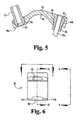
- FIGS. 6 -10 show various views of a hook-shaped member 30 according to one embodiment of the present invention.
- Member 30 includes a pair of opposing arms 32 and 34 which are joined at one end and spaced apart at the other end such that member 30 preferably has a "U" or "V" shaped side appearance.
- Arms 32 and 34 define a groove or pocket 33 therebetween for receiving a portion of bone.
- arms 32 and 34 are of different lengths. Referring to FIG. 8 , as one example the distance from the topmost outer radius at the joined end of the arms to the bottommost tip of arm 34 is about 14-15 millimeters, whereas the distance from the same outer radius to the bottommost tip of arm 32 is 16 to 17 millimeters. Referring to FIG.
- the inner, bone-contacting surfaces of arms 32 and 34 are preferably flat and define an included angle 36 of about 20 to 25 degrees.
- the present invention also contemplates those embodiments in which arms 32 and 34 are generally parallel, and also those embodiments in which the included angle is greater than 25 degrees.
- member 30 is fabricated from an alloy such as Ti-6AL-4V according to ASTM F-136. Although reference to specific dimensions and materials are given, the present invention is not limited to such specific details.
- arm 32 includes an aperture or through-hole 38 which is sized to accept the shank 27 of screw 26.
- Arm 32 also includes a radiused pocket 39 which is adapted and configured to permit three-dimensional rotation of surface 28.1 of screw head 28.
- opposing arm 34 includes at its free end a slot 40 located between a pair of extensions 41a and 41b. Extensions 41a and 41b are preferably spaced apart to accept the outer diameter of shank 27, as best seen in FIGS 1 and 2 . However, the present invention also contemplates those embodiments in which the shank of the bone screw passes through an aperture or clearance hole 140 defined by arm 134 of hook 130 (see FIG. 19B ).
- the present invention also contemplates those embodiments in which the arm of a hook 230 includes an aperture or slot 240 to receive the screw shank, except that the slot open end is rotated 90 degrees, such that the open end breaks laterally through a side of arm 34 (an orientation similar to notches 42a and 42b which laterally break through side surfaces of arm 32; see FIG. 19C ).
- arm 32 includes a pair of laterally opposing notches 42a and 42b which are sized to accept therein cable 50.
- a radiused notch 43 extends between notches 42a and 42b.
- notch 43 provides a relief space for cable 50, such that cable 50 does not protrude into the "U” or "V” shaped pocket area 33 and does not contact any bone located therein.
- a connector 60 provides means for coupling hook member 30 to rod 22.
- Connector 60 includes a pair of extended portions or opposing ends 60a and 60b which are interconnected by a middle section or rod-coupling portion 66.
- Portion 66 preferably has a shape that is complementary to the exterior shape of rod 22.
- the rod has a circular cross sectional shape and middle section 66 includes a complementary semi-circular shape.
- rod coupling portion 66 has a width or circumferential extent that is about the same as the diameter of rod 22.
- Rod coupling portion 66 spaces apart opposing ends 60a and 60b such that in some embodiments, the cable does not contact the rod after the cable is tightened.
- the present invention also contemplates those embodiments in which connector 60 is of a geometry such that the cable contacts portions of rod 22.
- Each end 60a and 60b preferably includes an internal smooth pocket 62 and 64, respectively. Pockets 62. and 64 rotatably receive fittings 52 and 54, respectively, and permit rotation of the fittings. Fittings 52 and 54 are attached to ends 50a and 50b, respectively, of cable 50.
- fitting 54 is a spherical or cable ball end firmly attached to cable end 50b
- fitting 52 is a crimpable cable fitting which is crimped tightly onto cable 50 prior to tightening and cutting cable 50 to the proper length.
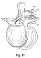
- FIGS. 11-14 depict various views of an apparatus 20 coupled to a vertebrae.
- the surgeon places hook-member 30 proximate to the vertebrae.
- Member 30 can be held by a forceps with male ends that fit within recesses 44a and 44b.
- Member 30 is prevented from backing away from the vertebrae by placement of a staple or insertion of screw 26, as shown in FIG. 1 .
- a connector 60 is placed on one side of a spinal rod 22.
- a length of cable including a fitting 54 is threaded through pocket 64 of connector and threaded around arm 32 of member 30, with the cable being running through 42a, 42b, and 43.
- the free end of cable 50 is threaded through pocket 62 at the other end of connector 60.
- a crimpable fitting 52 is placed over the free end of the cable, and moved into proximity with pocket 62.
- the cable is tightened such that the exterior of rod 22 rests within recess 66, with connector ends 60a and 60b straddling rod 22.
- fitting 52 is crimped tightly onto cable 50, and the excess length of cable 50 is removed.
- a spinal implant rod has attached to it a plurality of connectors, each connector being coupled by a flexible cable to a plurality of hook-shaped members.
- all flexible cables are tightened in order to bring each hook-shaped member into contact with the rod.
- the flexible cables are tightened such that none of the hook-shaped members are in contact with the rod. It is appreciated that in yet other embodiments, some of the cables are tightened to place one or more of the hooks in contact with the rod, and other cables are tightened such that one or more of the hooks are spaced apart from the rod.
- FIGS. 15-23 depict hook-shaped members according to various alternate embodiments of the present invention.
- the use of a prime (') designation refers to an element that is the same as the non-prime element, except for those differences shown or described.
- the use of an "N' prefix (NXX) refers to an element that is the same as the non-prefixed element (XX), except for those differences shown or described.
- hook-shaped member 30' includes reduced-width portions 42a' and 42b' along laterally opposing sides of arm 34'. As seen best in FIG. 16 , these reduced-width portions 42a' and 42b' blend into larger-width portions both at the juncture of arms 34' and 32', and also in the vicinity of aperture 38'. These reduced-width portions coact with slot 43' both to accurately locate the cable, and also to minimize sharp bends in the cable.
- FIG. 23 is a side elevational view of a hook-shaped member 430 according to another embodiment of the present invention. Member 430 includes a slot 443 that is open on either end and enclosed therebetween. Cable 450 (not shown) passes through slot 443.
Landscapes
- Health & Medical Sciences (AREA)
- Orthopedic Medicine & Surgery (AREA)
- Life Sciences & Earth Sciences (AREA)
- Neurology (AREA)
- Surgery (AREA)
- Heart & Thoracic Surgery (AREA)
- Engineering & Computer Science (AREA)
- Biomedical Technology (AREA)
- Nuclear Medicine, Radiotherapy & Molecular Imaging (AREA)
- Medical Informatics (AREA)
- Molecular Biology (AREA)
- Animal Behavior & Ethology (AREA)
- General Health & Medical Sciences (AREA)
- Public Health (AREA)
- Veterinary Medicine (AREA)
- Surgical Instruments (AREA)
- Prostheses (AREA)
Abstract
Claims (6)
- Appareil pour l'alignement de vertèbres, comprenant :une tige chirurgicale (22) ;un élément en forme de crochet (30) adapté et configuré pour recevoir une partie de l'os dans le crochet, ledit élément définissant une ouverture (38) à travers celui-ci ;un ancrage (26) ayant un corps (27) adapté et configuré pour une fixation dans un os et une tête (28), ledit corps étant adapté pour passer à travers l'ouverture (38) lorsqu'il est fixé à l'os ; et caractérisé parun câble (50) couplant ledit élément en forme de crochet à ladite tige ; et dans laquelle ladite ouverture (38) est une première ouverture, ledit élément en forme de crochet comprend des premier et second bras (32, 34) reliés à une extrémité et espacés à l'autre extrémité pour former une poche (33) entre eux pour recevoir la partie de l'os, l'un desdits bras définissant ladite première ouverture (38), l'autre desdits bras (32, 34) définissant une seconde ouverture (40), ledit corps étant adapté pour passer à travers la seconde ouverture (40) lorsqu'il est fixé à l'os.
- Appareil selon la revendication 1, dans lequel ladite première ouverture est un trou, et ladite seconde ouverture est une fente.
- Appareil selon la revendication 1, dans lequel ledit câble a des première et seconde extrémités (50a, 50b) et ladite tige a une section transversale courbe, et qui comprend en outre un élément de connexion (60) définissant une première poche (62) pour y recevoir la première extrémité et une seconde poche (64) pour y recevoir la seconde extrémité et une section centrale entre la première poche et la seconde poche, ladite section centrale ayant une courbure généralement complémentaire à la section transversale courbe de ladite tige.
- Appareil selon la revendication 2, dans lequel chacune desdites première et seconde extrémités dudit câble comprend une partie sphérique (52, 54), et chacune desdites première et seconde poches comprend un retrait sphérique adapté et configuré pour y recevoir la partie d'extrémité sphérique correspondante.
- Appareil selon la revendication 1, dans lequel ledit ancrage est une vis à os (26).
- Appareil selon la revendication 1, dans lequel ledit élément en forme de crochet définit une encoche (42) adaptée et configurée pour y recevoir ledit câble.
Applications Claiming Priority (5)
| Application Number | Priority Date | Filing Date | Title |
|---|---|---|---|
| US38233202P | 2002-05-21 | 2002-05-21 | |
| US382332P | 2002-05-21 | ||
| US38232002P | 2002-05-22 | 2002-05-22 | |
| US382320P | 2002-05-22 | ||
| PCT/US2003/015781 WO2003099148A2 (fr) | 2002-05-21 | 2003-05-20 | Cable de reduction et ancrage osseux |
Publications (2)
| Publication Number | Publication Date |
|---|---|
| EP1509148A2 EP1509148A2 (fr) | 2005-03-02 |
| EP1509148B1 true EP1509148B1 (fr) | 2011-03-16 |
Family
ID=29586954
Family Applications (1)
| Application Number | Title | Priority Date | Filing Date |
|---|---|---|---|
| EP03729024A Expired - Lifetime EP1509148B1 (fr) | 2002-05-21 | 2003-05-20 | Cable de reduction et ancrage osseux |
Country Status (6)
| Country | Link |
|---|---|
| US (1) | US7338490B2 (fr) |
| EP (1) | EP1509148B1 (fr) |
| JP (1) | JP4350647B2 (fr) |
| AU (1) | AU2003233587B2 (fr) |
| CA (1) | CA2486536A1 (fr) |
| WO (1) | WO2003099148A2 (fr) |
Families Citing this family (142)
| Publication number | Priority date | Publication date | Assignee | Title |
|---|---|---|---|---|
| US7833250B2 (en) | 2004-11-10 | 2010-11-16 | Jackson Roger P | Polyaxial bone screw with helically wound capture connection |
| US20050080486A1 (en) * | 2000-11-29 | 2005-04-14 | Fallin T. Wade | Facet joint replacement |
| US8353932B2 (en) | 2005-09-30 | 2013-01-15 | Jackson Roger P | Polyaxial bone anchor assembly with one-piece closure, pressure insert and plastic elongate member |
| US8292926B2 (en) | 2005-09-30 | 2012-10-23 | Jackson Roger P | Dynamic stabilization connecting member with elastic core and outer sleeve |
| US10729469B2 (en) * | 2006-01-09 | 2020-08-04 | Roger P. Jackson | Flexible spinal stabilization assembly with spacer having off-axis core member |
| US10258382B2 (en) | 2007-01-18 | 2019-04-16 | Roger P. Jackson | Rod-cord dynamic connection assemblies with slidable bone anchor attachment members along the cord |
| US7862587B2 (en) | 2004-02-27 | 2011-01-04 | Jackson Roger P | Dynamic stabilization assemblies, tool set and method |
| US20160242816A9 (en) * | 2001-05-09 | 2016-08-25 | Roger P. Jackson | Dynamic spinal stabilization assembly with elastic bumpers and locking limited travel closure mechanisms |
| US8876868B2 (en) | 2002-09-06 | 2014-11-04 | Roger P. Jackson | Helical guide and advancement flange with radially loaded lip |
| US6716214B1 (en) | 2003-06-18 | 2004-04-06 | Roger P. Jackson | Polyaxial bone screw with spline capture connection |
| US7621918B2 (en) | 2004-11-23 | 2009-11-24 | Jackson Roger P | Spinal fixation tool set and method |
| US7377923B2 (en) | 2003-05-22 | 2008-05-27 | Alphatec Spine, Inc. | Variable angle spinal screw assembly |
| US7967850B2 (en) | 2003-06-18 | 2011-06-28 | Jackson Roger P | Polyaxial bone anchor with helical capture connection, insert and dual locking assembly |
| US7776067B2 (en) | 2005-05-27 | 2010-08-17 | Jackson Roger P | Polyaxial bone screw with shank articulation pressure insert and method |
| US7766915B2 (en) | 2004-02-27 | 2010-08-03 | Jackson Roger P | Dynamic fixation assemblies with inner core and outer coil-like member |
| US8137386B2 (en) | 2003-08-28 | 2012-03-20 | Jackson Roger P | Polyaxial bone screw apparatus |
| US8398682B2 (en) | 2003-06-18 | 2013-03-19 | Roger P. Jackson | Polyaxial bone screw assembly |
| US8377102B2 (en) | 2003-06-18 | 2013-02-19 | Roger P. Jackson | Polyaxial bone anchor with spline capture connection and lower pressure insert |
| US8936623B2 (en) | 2003-06-18 | 2015-01-20 | Roger P. Jackson | Polyaxial bone screw assembly |
| US8366753B2 (en) | 2003-06-18 | 2013-02-05 | Jackson Roger P | Polyaxial bone screw assembly with fixed retaining structure |
| US11419642B2 (en) | 2003-12-16 | 2022-08-23 | Medos International Sarl | Percutaneous access devices and bone anchor assemblies |
| US7527638B2 (en) | 2003-12-16 | 2009-05-05 | Depuy Spine, Inc. | Methods and devices for minimally invasive spinal fixation element placement |
| US7179261B2 (en) | 2003-12-16 | 2007-02-20 | Depuy Spine, Inc. | Percutaneous access devices and bone anchor assemblies |
| US11241261B2 (en) | 2005-09-30 | 2022-02-08 | Roger P Jackson | Apparatus and method for soft spinal stabilization using a tensionable cord and releasable end structure |
| US7160300B2 (en) | 2004-02-27 | 2007-01-09 | Jackson Roger P | Orthopedic implant rod reduction tool set and method |
| US8152810B2 (en) | 2004-11-23 | 2012-04-10 | Jackson Roger P | Spinal fixation tool set and method |
| WO2005092218A1 (fr) | 2004-02-27 | 2005-10-06 | Jackson Roger P | Ensemble d'instruments de reduction de tige d'implant orthopedique et methode associee |
| US8114158B2 (en) | 2004-08-03 | 2012-02-14 | Kspine, Inc. | Facet device and method |
| US20060036324A1 (en) * | 2004-08-03 | 2006-02-16 | Dan Sachs | Adjustable spinal implant device and method |
| US20060058788A1 (en) * | 2004-08-27 | 2006-03-16 | Hammer Michael A | Multi-axial connection system |
| US8951290B2 (en) * | 2004-08-27 | 2015-02-10 | Blackstone Medical, Inc. | Multi-axial connection system |
| US7651502B2 (en) | 2004-09-24 | 2010-01-26 | Jackson Roger P | Spinal fixation tool set and method for rod reduction and fastener insertion |
| AU2005302633A1 (en) * | 2004-10-28 | 2006-05-11 | Axial Biotech, Inc. | Apparatus and method for concave scoliosis expansion |
| JP2008519656A (ja) | 2004-11-10 | 2008-06-12 | ロジャー・ピー・ジャクソン | 破断伸張部付の螺旋状案内及び前進フランジ |
| US8926672B2 (en) | 2004-11-10 | 2015-01-06 | Roger P. Jackson | Splay control closure for open bone anchor |
| US9216041B2 (en) | 2009-06-15 | 2015-12-22 | Roger P. Jackson | Spinal connecting members with tensioned cords and rigid sleeves for engaging compression inserts |
| US8444681B2 (en) | 2009-06-15 | 2013-05-21 | Roger P. Jackson | Polyaxial bone anchor with pop-on shank, friction fit retainer and winged insert |
| WO2006057837A1 (fr) | 2004-11-23 | 2006-06-01 | Jackson Roger P | Structure d'accrochage pour outil de fixation spinale |
| US8308782B2 (en) | 2004-11-23 | 2012-11-13 | Jackson Roger P | Bone anchors with longitudinal connecting member engaging inserts and closures for fixation and optional angulation |
| US9168069B2 (en) | 2009-06-15 | 2015-10-27 | Roger P. Jackson | Polyaxial bone anchor with pop-on shank and winged insert with lower skirt for engaging a friction fit retainer |
| US9980753B2 (en) | 2009-06-15 | 2018-05-29 | Roger P Jackson | pivotal anchor with snap-in-place insert having rotation blocking extensions |
| US8172855B2 (en) | 2004-11-24 | 2012-05-08 | Abdou M S | Devices and methods for inter-vertebral orthopedic device placement |
| US10076361B2 (en) | 2005-02-22 | 2018-09-18 | Roger P. Jackson | Polyaxial bone screw with spherical capture, compression and alignment and retention structures |
| US7901437B2 (en) | 2007-01-26 | 2011-03-08 | Jackson Roger P | Dynamic stabilization member with molded connection |
| US7628799B2 (en) | 2005-08-23 | 2009-12-08 | Aesculap Ag & Co. Kg | Rod to rod connector |
| US8105368B2 (en) | 2005-09-30 | 2012-01-31 | Jackson Roger P | Dynamic stabilization connecting member with slitted core and outer sleeve |
| US8100946B2 (en) | 2005-11-21 | 2012-01-24 | Synthes Usa, Llc | Polyaxial bone anchors with increased angulation |
| US7704271B2 (en) | 2005-12-19 | 2010-04-27 | Abdou M Samy | Devices and methods for inter-vertebral orthopedic device placement |
| US20080058808A1 (en) * | 2006-06-14 | 2008-03-06 | Spartek Medical, Inc. | Implant system and method to treat degenerative disorders of the spine |
| EP2088945A4 (fr) | 2006-12-08 | 2010-02-17 | Roger P Jackson | Systeme d'instruments pour implants rachidiens dynamiques |
| US8475498B2 (en) | 2007-01-18 | 2013-07-02 | Roger P. Jackson | Dynamic stabilization connecting member with cord connection |
| US8366745B2 (en) * | 2007-05-01 | 2013-02-05 | Jackson Roger P | Dynamic stabilization assembly having pre-compressed spacers with differential displacements |
| US10792074B2 (en) | 2007-01-22 | 2020-10-06 | Roger P. Jackson | Pivotal bone anchor assemly with twist-in-place friction fit insert |
| US10383660B2 (en) | 2007-05-01 | 2019-08-20 | Roger P. Jackson | Soft stabilization assemblies with pretensioned cords |
| US8979904B2 (en) | 2007-05-01 | 2015-03-17 | Roger P Jackson | Connecting member with tensioned cord, low profile rigid sleeve and spacer with torsion control |
| WO2008151091A1 (fr) | 2007-06-05 | 2008-12-11 | Spartek Medical, Inc. | Système de tiges déflectrices pour un système d'implants spinaux à stabilisation dynamique et préservation du mouvement, et procédé correspondant |
| US8114134B2 (en) | 2007-06-05 | 2012-02-14 | Spartek Medical, Inc. | Spinal prosthesis having a three bar linkage for motion preservation and dynamic stabilization of the spine |
| US8048115B2 (en) | 2007-06-05 | 2011-11-01 | Spartek Medical, Inc. | Surgical tool and method for implantation of a dynamic bone anchor |
| US8021396B2 (en) | 2007-06-05 | 2011-09-20 | Spartek Medical, Inc. | Configurable dynamic spinal rod and method for dynamic stabilization of the spine |
| US8105356B2 (en) | 2007-06-05 | 2012-01-31 | Spartek Medical, Inc. | Bone anchor with a curved mounting element for a dynamic stabilization and motion preservation spinal implantation system and method |
| US8092501B2 (en) | 2007-06-05 | 2012-01-10 | Spartek Medical, Inc. | Dynamic spinal rod and method for dynamic stabilization of the spine |
| US8083772B2 (en) | 2007-06-05 | 2011-12-27 | Spartek Medical, Inc. | Dynamic spinal rod assembly and method for dynamic stabilization of the spine |
| EP2155086B1 (fr) | 2007-06-06 | 2016-05-04 | K2M, Inc. | Dispositif médical de correction d'une difformité |
| US9439681B2 (en) | 2007-07-20 | 2016-09-13 | DePuy Synthes Products, Inc. | Polyaxial bone fixation element |
| US8790380B2 (en) * | 2007-07-26 | 2014-07-29 | Dynamic Spine, Llc | Segmental orthopaedic device for spinal elongation and for treatment of scoliosis |
| US9204908B2 (en) * | 2007-07-26 | 2015-12-08 | Dynamic Spine, Llc | Segmental orthopedic device for spinal elongation and for treatment of scoliosis |
| US9622789B2 (en) * | 2008-01-14 | 2017-04-18 | K2M, Inc. | Spinal fixation device and method |
| US8211155B2 (en) | 2008-02-26 | 2012-07-03 | Spartek Medical, Inc. | Load-sharing bone anchor having a durable compliant member and method for dynamic stabilization of the spine |
| US8097024B2 (en) | 2008-02-26 | 2012-01-17 | Spartek Medical, Inc. | Load-sharing bone anchor having a deflectable post and method for stabilization of the spine |
| US8267979B2 (en) | 2008-02-26 | 2012-09-18 | Spartek Medical, Inc. | Load-sharing bone anchor having a deflectable post and axial spring and method for dynamic stabilization of the spine |
| US8083775B2 (en) | 2008-02-26 | 2011-12-27 | Spartek Medical, Inc. | Load-sharing bone anchor having a natural center of rotation and method for dynamic stabilization of the spine |
| US8016861B2 (en) | 2008-02-26 | 2011-09-13 | Spartek Medical, Inc. | Versatile polyaxial connector assembly and method for dynamic stabilization of the spine |
| US8333792B2 (en) | 2008-02-26 | 2012-12-18 | Spartek Medical, Inc. | Load-sharing bone anchor having a deflectable post and method for dynamic stabilization of the spine |
| US8337536B2 (en) | 2008-02-26 | 2012-12-25 | Spartek Medical, Inc. | Load-sharing bone anchor having a deflectable post with a compliant ring and method for stabilization of the spine |
| US20100030224A1 (en) | 2008-02-26 | 2010-02-04 | Spartek Medical, Inc. | Surgical tool and method for connecting a dynamic bone anchor and dynamic vertical rod |
| US8057517B2 (en) | 2008-02-26 | 2011-11-15 | Spartek Medical, Inc. | Load-sharing component having a deflectable post and centering spring and method for dynamic stabilization of the spine |
| US8025678B2 (en) * | 2008-03-26 | 2011-09-27 | Depuy Spine, Inc. | Interspinous process spacer having tight access offset hooks |
| US8313512B2 (en) * | 2008-03-26 | 2012-11-20 | Depuy Spine, Inc. | S-shaped interspinous process spacer having tight access offset hooks |
| US8177811B2 (en) * | 2008-07-25 | 2012-05-15 | Clariance | Joint prosthesis for total lumbar arthroplasty by posterior approach |
| CA2739997C (fr) | 2008-08-01 | 2013-08-13 | Roger P. Jackson | Element longitudinal de liaison avec cordons tendus gaines |
| KR20110073438A (ko) * | 2008-09-12 | 2011-06-29 | 신세스 게엠바하 | 척추 안정화 및 안내 고정 시스템 |
| EP2339975B1 (fr) | 2008-09-29 | 2015-03-25 | Synthes GmbH | Vis polyaxiale à chargement par le bas et ensemble tige |
| WO2010062736A1 (fr) | 2008-11-03 | 2010-06-03 | Synthes Usa, Llc | Ensemble fixation osseuse plane |
| US8828058B2 (en) * | 2008-11-11 | 2014-09-09 | Kspine, Inc. | Growth directed vertebral fixation system with distractible connector(s) and apical control |
| US8357183B2 (en) | 2009-03-26 | 2013-01-22 | Kspine, Inc. | Semi-constrained anchoring system |
| JP2012523927A (ja) | 2009-04-15 | 2012-10-11 | ジンテス ゲゼルシャフト ミット ベシュレンクテル ハフツング | 脊椎構成物のための修正コネクタ |
| CN103826560A (zh) | 2009-06-15 | 2014-05-28 | 罗杰.P.杰克逊 | 具有套接杆和带摩擦配合压缩套爪的带翼插件的多轴骨锚 |
| US8998959B2 (en) | 2009-06-15 | 2015-04-07 | Roger P Jackson | Polyaxial bone anchors with pop-on shank, fully constrained friction fit retainer and lock and release insert |
| US9668771B2 (en) | 2009-06-15 | 2017-06-06 | Roger P Jackson | Soft stabilization assemblies with off-set connector |
| US11229457B2 (en) | 2009-06-15 | 2022-01-25 | Roger P. Jackson | Pivotal bone anchor assembly with insert tool deployment |
| US20100318129A1 (en) * | 2009-06-16 | 2010-12-16 | Kspine, Inc. | Deformity alignment system with reactive force balancing |
| JP5654584B2 (ja) | 2009-06-17 | 2015-01-14 | ジンテス ゲゼルシャフト ミット ベシュレンクテル ハフツング | 脊柱構築用の修正コネクタ |
| FR2948554B1 (fr) * | 2009-07-31 | 2012-12-21 | Spineway | Dispositif extra- discal de stabilisation intervertebrale |
| US9168071B2 (en) | 2009-09-15 | 2015-10-27 | K2M, Inc. | Growth modulation system |
| AU2010303934B2 (en) | 2009-10-05 | 2014-03-27 | Roger P. Jackson | Polyaxial bone anchor with non-pivotable retainer and pop-on shank, some with friction fit |
| WO2011069000A2 (fr) | 2009-12-02 | 2011-06-09 | Spartek Medical, Inc. | Prothèse spinale à profil mince incorporant un ancrage osseux ayant un montant déformable et une tige spinale composite |
| US8764806B2 (en) | 2009-12-07 | 2014-07-01 | Samy Abdou | Devices and methods for minimally invasive spinal stabilization and instrumentation |
| US20110257687A1 (en) * | 2010-04-19 | 2011-10-20 | Warsaw Orthopedic, Inc. | Load sharing bone fastener and methods of use |
| US12383311B2 (en) | 2010-05-14 | 2025-08-12 | Roger P. Jackson | Pivotal bone anchor assembly and method for use thereof |
| US9277950B2 (en) | 2010-06-10 | 2016-03-08 | Dynamic Spine, Llc | Low-profile, uniplanar bone screw |
| US20110307018A1 (en) | 2010-06-10 | 2011-12-15 | Spartek Medical, Inc. | Adaptive spinal rod and methods for stabilization of the spine |
| EP2422728B1 (fr) * | 2010-08-25 | 2013-01-30 | Zimmer Spine | Ancrage pour la fixation sur une structure osseuse |
| JP2013540468A (ja) | 2010-09-08 | 2013-11-07 | ロジャー・ピー・ジャクソン | 弾性部および非弾性部を有する動的固定化部材 |
| EP2635212A4 (fr) | 2010-11-02 | 2013-11-20 | Jackson Roger P | Dispositif polyaxial d'ancrage osseux à tige fixée par pression et à élément de retenue pivotant |
| WO2012128825A1 (fr) | 2011-03-24 | 2012-09-27 | Jackson Roger P | Ancrage osseux polyaxial avec articulation composée et tige enclipsable |
| CN103781429B (zh) | 2011-06-03 | 2017-02-15 | 科斯班公司 | 脊柱矫正系统致动器 |
| US9247962B2 (en) | 2011-08-15 | 2016-02-02 | K2M, Inc. | Laminar hook insertion device |
| EP2755582B1 (fr) * | 2011-09-14 | 2023-07-26 | OrthoPediatrics Corp. | Pince d'attache et système d'implant |
| US8845728B1 (en) | 2011-09-23 | 2014-09-30 | Samy Abdou | Spinal fixation devices and methods of use |
| US9451987B2 (en) | 2011-11-16 | 2016-09-27 | K2M, Inc. | System and method for spinal correction |
| WO2014172632A2 (fr) | 2011-11-16 | 2014-10-23 | Kspine, Inc. | Correction et stabilisation secondaire de la colonne vertébrale |
| US8920472B2 (en) | 2011-11-16 | 2014-12-30 | Kspine, Inc. | Spinal correction and secondary stabilization |
| US9468468B2 (en) | 2011-11-16 | 2016-10-18 | K2M, Inc. | Transverse connector for spinal stabilization system |
| US9468469B2 (en) | 2011-11-16 | 2016-10-18 | K2M, Inc. | Transverse coupler adjuster spinal correction systems and methods |
| US8911479B2 (en) | 2012-01-10 | 2014-12-16 | Roger P. Jackson | Multi-start closures for open implants |
| US9283001B2 (en) | 2012-01-18 | 2016-03-15 | Globus Medical, Inc. | Systems for spinal stabilization |
| US8430916B1 (en) | 2012-02-07 | 2013-04-30 | Spartek Medical, Inc. | Spinal rod connectors, methods of use, and spinal prosthesis incorporating spinal rod connectors |
| US20130226240A1 (en) | 2012-02-22 | 2013-08-29 | Samy Abdou | Spinous process fixation devices and methods of use |
| US9295488B2 (en) | 2012-08-09 | 2016-03-29 | Wilson T. Asfora | Joint fusion |
| US9198767B2 (en) | 2012-08-28 | 2015-12-01 | Samy Abdou | Devices and methods for spinal stabilization and instrumentation |
| US9320617B2 (en) | 2012-10-22 | 2016-04-26 | Cogent Spine, LLC | Devices and methods for spinal stabilization and instrumentation |
| US8911478B2 (en) | 2012-11-21 | 2014-12-16 | Roger P. Jackson | Splay control closure for open bone anchor |
| US10058354B2 (en) | 2013-01-28 | 2018-08-28 | Roger P. Jackson | Pivotal bone anchor assembly with frictional shank head seating surfaces |
| US8852239B2 (en) | 2013-02-15 | 2014-10-07 | Roger P Jackson | Sagittal angle screw with integral shank and receiver |
| US20140277155A1 (en) | 2013-03-14 | 2014-09-18 | K2M, Inc. | Taper lock hook |
| US9468471B2 (en) | 2013-09-17 | 2016-10-18 | K2M, Inc. | Transverse coupler adjuster spinal correction systems and methods |
| US9566092B2 (en) | 2013-10-29 | 2017-02-14 | Roger P. Jackson | Cervical bone anchor with collet retainer and outer locking sleeve |
| US9717533B2 (en) | 2013-12-12 | 2017-08-01 | Roger P. Jackson | Bone anchor closure pivot-splay control flange form guide and advancement structure |
| US9597124B2 (en) * | 2014-01-09 | 2017-03-21 | Warsaw Orthopedic, Inc. | Spinal correction system and method |
| US9451993B2 (en) | 2014-01-09 | 2016-09-27 | Roger P. Jackson | Bi-radial pop-on cervical bone anchor |
| US9486252B2 (en) * | 2014-01-09 | 2016-11-08 | Warsaw Orthopedic, Inc. | Spinal correction system and method |
| US20150230828A1 (en) | 2014-02-20 | 2015-08-20 | K2M, Inc. | Spinal fixation device |
| US9597119B2 (en) | 2014-06-04 | 2017-03-21 | Roger P. Jackson | Polyaxial bone anchor with polymer sleeve |
| US10064658B2 (en) | 2014-06-04 | 2018-09-04 | Roger P. Jackson | Polyaxial bone anchor with insert guides |
| US10857003B1 (en) | 2015-10-14 | 2020-12-08 | Samy Abdou | Devices and methods for vertebral stabilization |
| WO2017156382A1 (fr) * | 2016-03-10 | 2017-09-14 | Nuvasive, Inc. | Ancrage osseux à élément d'achat déployable |
| US10575876B2 (en) | 2016-04-20 | 2020-03-03 | K2M, Inc. | Spinal stabilization assemblies with bone hooks |
| DE112017003415T5 (de) | 2016-07-07 | 2019-03-28 | Mark, S. Stern | Dornfortsatz-laminaklemmvorrichtung |
| US10744000B1 (en) | 2016-10-25 | 2020-08-18 | Samy Abdou | Devices and methods for vertebral bone realignment |
| US10973648B1 (en) | 2016-10-25 | 2021-04-13 | Samy Abdou | Devices and methods for vertebral bone realignment |
| US11179248B2 (en) | 2018-10-02 | 2021-11-23 | Samy Abdou | Devices and methods for spinal implantation |
| US10869696B2 (en) * | 2019-01-30 | 2020-12-22 | Medos International Sarl | Surgical device for spinal fixation |
Family Cites Families (100)
| Publication number | Priority date | Publication date | Assignee | Title |
|---|---|---|---|---|
| US2574579A (en) | 1947-07-28 | 1951-11-13 | Boeing Co | Cable connector |
| US2509272A (en) | 1947-08-12 | 1950-05-30 | Curtiss Wright Corp | Aircraft control mechanism |
| FR2289164A1 (fr) | 1974-11-04 | 1976-05-28 | Tornier Rene | Perfectionnements aux dispositifs pour le traitement de la scoliose |
| PL105977B1 (pl) | 1976-06-28 | 1979-11-30 | Wyzsza Szkola Inzynierska | Przyrzad do korekcji skrzywien kregoslupa |
| PL127121B1 (en) | 1980-07-30 | 1983-09-30 | Wyzsza Szkola Inzynierska | Surgical strut for treating spinal affections |
| DE3121271A1 (de) | 1981-05-29 | 1982-12-23 | Max Bernhard 7900 Ulm Ulrich | Distraktionsgeraet zur korrektur insbesondere kyphotischer wirbelsaeulenbereiche |
| PL131829B1 (en) | 1982-01-18 | 1985-01-31 | Wyzsza Szkola Inzynierska Gagari | Surgical strut for treating spine anomalies |
| US4567884A (en) | 1982-12-01 | 1986-02-04 | Edwards Charles C | Spinal hook |
| US4805602A (en) * | 1986-11-03 | 1989-02-21 | Danninger Medical Technology | Transpedicular screw and rod system |
| US5007909A (en) * | 1986-11-05 | 1991-04-16 | Chaim Rogozinski | Apparatus for internally fixing the spine |
| US4790303A (en) | 1987-03-11 | 1988-12-13 | Acromed Corporation | Apparatus and method for securing bone graft |
| FR2614781B1 (fr) | 1987-05-05 | 1989-08-04 | Galline Yves | Dispositif d'attachement et outils pour sa mise en place, notamment pour attacher le grand trochanter au femur |
| GB8716925D0 (en) | 1987-07-17 | 1987-08-26 | Mehdian S M H | Apparatus for treatment of spinal disorders |
| US4887595A (en) | 1987-07-29 | 1989-12-19 | Acromed Corporation | Surgically implantable device for spinal columns |
| FR2633177B1 (fr) | 1988-06-24 | 1991-03-08 | Fabrication Materiel Orthopedi | Implant pour dispositif d'osteosynthese rachidienne, notamment en traumatologie |
| FR2642642B1 (fr) | 1989-02-03 | 1997-08-22 | Cotrel Yves | Implant d'osteosynthese posterieure rachidienne |
| US5000165A (en) | 1989-05-15 | 1991-03-19 | Watanabe Robert S | Lumbar spine rod fixation system |
| FR2659225B1 (fr) | 1990-03-08 | 1995-09-08 | Sofamor | Dispositif de fixation transverse pour assurer une liaison transversale rigide entre deux tiges d'un systeme d'osteosynthese rachidienne. |
| DE9006646U1 (de) | 1990-06-13 | 1990-08-23 | Howmedica GmbH, 2314 Schönkirchen | Vorrichtung zum Verspannen von Wirbeln der menschlichen Wirbelsäule |
| SE470047B (sv) | 1991-05-15 | 1993-11-01 | Sven Olerud | För kirurgisk användning avsedd klämback |
| US5242446A (en) | 1992-01-02 | 1993-09-07 | Acromed Corporation | Connector for a spinal column corrective device |
| US5250049A (en) * | 1992-01-10 | 1993-10-05 | Michael Roger H | Bone and tissue connectors |
| NL9200288A (nl) | 1992-02-17 | 1993-09-16 | Acromed Bv | Inrichting ter fixatie van ten minste een gedeelte van de cervicale en/of thoracale wervelkolom van de mens. |
| AU659912B2 (en) | 1992-03-10 | 1995-06-01 | Bristol-Myers Squibb Company | Perpendicular rod connector for spinal fixation device |
| US5304178A (en) | 1992-05-29 | 1994-04-19 | Acromed Corporation | Sublaminar wire |
| ES2099326T3 (es) | 1992-08-12 | 1997-05-16 | Synthes Ag | Elemento de fijacion del raquis. |
| US5312410A (en) | 1992-12-07 | 1994-05-17 | Danek Medical, Inc. | Surgical cable tensioner |
| WO1994017746A1 (fr) * | 1993-02-05 | 1994-08-18 | Synthes Ag, Chur | Crochet utilise pour traiter des deformations de la colonne vertebrale |
| CA2106776C (fr) | 1993-03-15 | 1998-12-29 | Johannes Fridolin Schlapfer | Crochet a vis pour le traitement de difformites de la colonne vertebrale |
| US5423820A (en) | 1993-07-20 | 1995-06-13 | Danek Medical, Inc. | Surgical cable and crimp |
| US6004327A (en) | 1993-08-03 | 1999-12-21 | Stryker Technologies Corporation | Ratcheting compression device |
| US5395374A (en) | 1993-09-02 | 1995-03-07 | Danek Medical, Inc. | Orthopedic cabling method and apparatus |
| US5417690A (en) | 1993-09-20 | 1995-05-23 | Codman & Shurtleff, Inc. | Surgical cable |
| US5415658A (en) | 1993-12-14 | 1995-05-16 | Pioneer Laboratories, Inc. | Surgical cable loop connector |
| US5569253A (en) | 1994-03-29 | 1996-10-29 | Danek Medical, Inc. | Variable-angle surgical cable crimp assembly and method |
| FR2718944B1 (fr) | 1994-04-20 | 1996-08-30 | Pierre Roussouly | Dispositif de stabilisation d'ancrage orthopédique. |
| DE9409123U1 (de) | 1994-06-04 | 1994-09-01 | Howmedica GmbH, 24232 Schönkirchen | Vorrichtung zum Stabilisieren bzw. Komprimieren oder Distrahieren von Abschnitten der Wirbelsäule |
| FR2721501B1 (fr) | 1994-06-24 | 1996-08-23 | Fairant Paulette | Prothèses des facettes articulaires vertébrales. |
| WO1996014801A1 (fr) | 1994-11-16 | 1996-05-23 | Advanced Spine Fixation Systems, Incorporated | Crochets de fixation segmentaire des lames vertebrales |
| US5591235A (en) | 1995-03-15 | 1997-01-07 | Kuslich; Stephen D. | Spinal fixation device |
| US5810818A (en) | 1995-10-23 | 1998-09-22 | Fastenetix, Llc | Spinal hook implant having a low blade and S swivel hook |
| US5702399A (en) | 1996-05-16 | 1997-12-30 | Pioneer Laboratories, Inc. | Surgical cable screw connector |
| US5782831A (en) | 1996-11-06 | 1998-07-21 | Sdgi Holdings, Inc. | Method an device for spinal deformity reduction using a cable and a cable tensioning system |
| WO1998025534A1 (fr) | 1996-12-12 | 1998-06-18 | Synthes Ag Chur | Dispositif pour relier un support longitudinal avec une vis pediculaire |
| AU725487B2 (en) | 1997-01-22 | 2000-10-12 | Synthes Gmbh | Device for connecting a longitudinal bar to a pedicle screw |
| US6248105B1 (en) | 1997-05-17 | 2001-06-19 | Synthes (U.S.A.) | Device for connecting a longitudinal support with a pedicle screw |
| US5964769A (en) | 1997-08-26 | 1999-10-12 | Spinal Concepts, Inc. | Surgical cable system and method |
| US6053921A (en) | 1997-08-26 | 2000-04-25 | Spinal Concepts, Inc. | Surgical cable system and method |
| US6660010B2 (en) | 1998-01-27 | 2003-12-09 | Scimed Life Systems, Inc. | Bone anchor placement device with recessed anchor mount |
| US6066173A (en) | 1998-01-28 | 2000-05-23 | Ethicon, Inc. | Method and apparatus for fixing a graft in a bone tunnel |
| US6045551A (en) | 1998-02-06 | 2000-04-04 | Bonutti; Peter M. | Bone suture |
| US6241769B1 (en) | 1998-05-06 | 2001-06-05 | Cortek, Inc. | Implant for spinal fusion |
| WO1999062417A1 (fr) | 1998-06-04 | 1999-12-09 | Synthes Ag Chur | Rivet aveugle chirurgical dote d'un element de fermeture |
| US6648903B1 (en) | 1998-09-08 | 2003-11-18 | Pierson, Iii Raymond H. | Medical tensioning system |
| WO2000015125A1 (fr) | 1998-09-11 | 2000-03-23 | Synthes Ag Chur | Systeme de fixation vertebrale a angle variable |
| FR2783411B1 (fr) | 1998-09-18 | 2000-12-01 | Eurosurgical | Dispositif d'osteosynthese rachidienne posterieure |
| US6368326B1 (en) | 1998-09-28 | 2002-04-09 | Daos Limited | Internal cord fixation device |
| WO2000028906A1 (fr) | 1998-11-17 | 2000-05-25 | Synthes Ag Chur | Clou d'osteosynthese intramedullaire pour le traitement operatoire de fractures de l'avant bras |
| US6123707A (en) | 1999-01-13 | 2000-09-26 | Spinal Concepts, Inc. | Reduction instrument |
| US6086590A (en) | 1999-02-02 | 2000-07-11 | Pioneer Laboratories, Inc. | Cable connector for orthopaedic rod |
| NZ513746A (en) | 1999-03-09 | 2001-09-28 | Synthes Ag | Bone plate |
| US6299613B1 (en) | 1999-04-23 | 2001-10-09 | Sdgi Holdings, Inc. | Method for the correction of spinal deformities through vertebral body tethering without fusion |
| US6436099B1 (en) | 1999-04-23 | 2002-08-20 | Sdgi Holdings, Inc. | Adjustable spinal tether |
| DK1191890T3 (da) | 1999-07-07 | 2005-06-06 | Synthes Ag | Vinkeljusterbar knogleskrue og indretning til osteosyntetisk knoglefiksering |
| ES2201722T3 (es) | 1999-07-07 | 2004-03-16 | Synthes Ag Chur | Tornillo para hueso con cabeza de tornillo constituida axialmente de dos partes. |
| US6251111B1 (en) | 1999-10-20 | 2001-06-26 | Sdgi Holdings, Inc. | Jack for pulling a vertebral anchor |
| US6558389B2 (en) | 1999-11-30 | 2003-05-06 | Ron Clark | Endosteal tibial ligament fixation with adjustable tensioning |
| US6290701B1 (en) | 2000-01-11 | 2001-09-18 | Albert Enayati | Bioabsorbable rivet bone fastener |
| US20020133155A1 (en) | 2000-02-25 | 2002-09-19 | Ferree Bret A. | Cross-coupled vertebral stabilizers incorporating spinal motion restriction |
| US6514255B1 (en) | 2000-02-25 | 2003-02-04 | Bret Ferree | Sublaminar spinal fixation apparatus |
| US6423065B2 (en) | 2000-02-25 | 2002-07-23 | Bret A. Ferree | Cross-coupled vertebral stabilizers including cam-operated cable connectors |
| US6248107B1 (en) | 2000-03-15 | 2001-06-19 | Sdgi Holdings, Inc. | System for reducing the displacement of a vertebra |
| AU2000235484B2 (en) | 2000-04-10 | 2004-10-14 | Synthes Gmbh | Osteosynthetic anchoring element |
| US7172615B2 (en) | 2000-05-19 | 2007-02-06 | Coapt Systems, Inc. | Remotely anchored tissue fixation device |
| US6576018B1 (en) | 2000-06-23 | 2003-06-10 | Edward S. Holt | Apparatus configuration and method for treating flatfoot |
| AU2000252043B2 (en) | 2000-06-26 | 2004-10-21 | Synthes Gmbh | Bone plate for osteosynthesis |
| US6605091B1 (en) | 2000-06-30 | 2003-08-12 | Pioneer Laboratories, Inc. | Surgical cable assembly and method |
| US6524315B1 (en) | 2000-08-08 | 2003-02-25 | Depuy Acromed, Inc. | Orthopaedic rod/plate locking mechanism |
| MXPA03001628A (es) | 2000-08-24 | 2003-06-24 | Synthes Ag | Un dispositivo para la union de un elemento de fijacion de huesos con una varilla longitudinal. |
| BR0017331A (pt) | 2000-09-07 | 2003-06-03 | Synthes Ag | Dispositivo para o tratamento de fratura de ossos e/ou para a fixação de implantes cirúrgicos |
| US6277120B1 (en) | 2000-09-20 | 2001-08-21 | Kevin Jon Lawson | Cable-anchor system for spinal fixation |
| EP1192908A3 (fr) | 2000-10-02 | 2004-05-26 | Howmedica Osteonics Corp. | Dispositif et méthode de reconstruction de la colonne vertébrale |
| US6953462B2 (en) | 2000-10-05 | 2005-10-11 | The Cleveland Clinic Foundation | Apparatus for implantation into bone |
| US6468309B1 (en) | 2000-10-05 | 2002-10-22 | Cleveland Clinic Foundation | Method and apparatus for stabilizing adjacent bones |
| US6551320B2 (en) | 2000-11-08 | 2003-04-22 | The Cleveland Clinic Foundation | Method and apparatus for correcting spinal deformity |
| US6527774B2 (en) | 2000-11-08 | 2003-03-04 | The Cleveland Clinic Foundation | Apparatus for attaching fractured sections of bone |
| US6488683B2 (en) | 2000-11-08 | 2002-12-03 | Cleveland Clinic Foundation | Method and apparatus for correcting spinal deformity |
| US6551319B2 (en) | 2000-11-08 | 2003-04-22 | The Cleveland Clinic Foundation | Apparatus for implantation into bone |
| US6544265B2 (en) | 2000-11-08 | 2003-04-08 | The Cleveland Clinic Foundation | Apparatus for implantation into bone related applications |
| US6719758B2 (en) | 2001-01-19 | 2004-04-13 | Aesculap Ag & Co. Kg | Kirschner wire with a holding device for surgical procedures |
| US6645211B2 (en) | 2001-02-07 | 2003-11-11 | Howmedica Osteonics Corp. | Orthopedic support system and method of installation |
| US6863689B2 (en) | 2001-07-16 | 2005-03-08 | Spinecore, Inc. | Intervertebral spacer having a flexible wire mesh vertebral body contact element |
| US7604664B2 (en) | 2001-07-16 | 2009-10-20 | Spinecore, Inc. | Spinal baseplates with ball joint coupling and a retaining member |
| JP4499310B2 (ja) | 2001-04-12 | 2010-07-07 | 経憲 武井 | 手術器具 |
| US20030078579A1 (en) | 2001-04-19 | 2003-04-24 | Ferree Bret A. | Annular repair devices and methods |
| US6511484B2 (en) | 2001-06-29 | 2003-01-28 | Depuy Acromed, Inc. | Tool and system for aligning and applying fastener to implanted anchor |
| US6855105B2 (en) | 2001-07-11 | 2005-02-15 | Jackson, Iii Avery M. | Endoscopic pedicle probe |
| US20030050644A1 (en) | 2001-09-11 | 2003-03-13 | Boucher Ryan P. | Systems and methods for accessing and treating diseased or fractured bone employing a guide wire |
| US6736819B2 (en) | 2001-10-18 | 2004-05-18 | Kishore Tipirneni | System and method for fixation of bone fractures |
| US6730092B2 (en) | 2001-12-03 | 2004-05-04 | Pioneer Laboratories, Inc. | System and method for bone fixation |
-
2003
- 2003-05-20 EP EP03729024A patent/EP1509148B1/fr not_active Expired - Lifetime
- 2003-05-20 WO PCT/US2003/015781 patent/WO2003099148A2/fr not_active Ceased
- 2003-05-20 JP JP2004506676A patent/JP4350647B2/ja not_active Expired - Fee Related
- 2003-05-20 CA CA002486536A patent/CA2486536A1/fr not_active Abandoned
- 2003-05-20 AU AU2003233587A patent/AU2003233587B2/en not_active Ceased
- 2003-05-21 US US10/442,821 patent/US7338490B2/en not_active Expired - Lifetime
Also Published As
| Publication number | Publication date |
|---|---|
| WO2003099148A3 (fr) | 2004-04-01 |
| AU2003233587B2 (en) | 2008-12-18 |
| JP2005525908A (ja) | 2005-09-02 |
| JP4350647B2 (ja) | 2009-10-21 |
| US7338490B2 (en) | 2008-03-04 |
| CA2486536A1 (fr) | 2003-12-04 |
| EP1509148A2 (fr) | 2005-03-02 |
| AU2003233587A1 (en) | 2003-12-12 |
| WO2003099148A2 (fr) | 2003-12-04 |
| US20040111091A1 (en) | 2004-06-10 |
Similar Documents
| Publication | Publication Date | Title |
|---|---|---|
| AU2003233587B2 (en) | Vertebrae bone anchor and cable for coupling it to a rod | |
| US12137943B2 (en) | Semi-constrained anchoring system | |
| US5797916A (en) | Trochanteric reattachment cerclage device | |
| US9918748B2 (en) | Spinal rod connector | |
| US7744632B2 (en) | Rod to rod connector | |
| EP1545353B1 (fr) | Connecteur pour vis pediculaire | |
| US7008423B2 (en) | Spinal osteosynthesis system for anterior fixation | |
| US6099527A (en) | Bone protector and method | |
| AU732474B2 (en) | Surgical cable system and method | |
| AU2019200888B2 (en) | Semi-constrained anchoring system for correcting a spinal deformity | |
| JPH11501235A (ja) | 特にロッドのための脊椎用装着具 | |
| KR20020093842A (ko) | 다중축 뼈-고정 시스템 | |
| EP1161191A2 (fr) | Instruments d'osteosynthese vertebrale | |
| US20250032153A1 (en) | Semi-Constrained Anchoring System |
Legal Events
| Date | Code | Title | Description |
|---|---|---|---|
| PUAI | Public reference made under article 153(3) epc to a published international application that has entered the european phase |
Free format text: ORIGINAL CODE: 0009012 |
|
| 17P | Request for examination filed |
Effective date: 20041215 |
|
| AK | Designated contracting states |
Kind code of ref document: A2 Designated state(s): AT BE BG CH CY CZ DE DK EE ES FI FR GB GR HU IE IT LI LU MC NL PT RO SE SI SK TR |
|
| AX | Request for extension of the european patent |
Extension state: AL LT LV MK |
|
| DAX | Request for extension of the european patent (deleted) | ||
| RBV | Designated contracting states (corrected) |
Designated state(s): BE CH FR LI |
|
| REG | Reference to a national code |
Ref country code: DE Ref legal event code: 8566 |
|
| RAP1 | Party data changed (applicant data changed or rights of an application transferred) |
Owner name: WARSAW ORTHOPEDIC, INC. |
|
| 17Q | First examination report despatched |
Effective date: 20071011 |
|
| GRAP | Despatch of communication of intention to grant a patent |
Free format text: ORIGINAL CODE: EPIDOSNIGR1 |
|
| GRAS | Grant fee paid |
Free format text: ORIGINAL CODE: EPIDOSNIGR3 |
|
| GRAA | (expected) grant |
Free format text: ORIGINAL CODE: 0009210 |
|
| AK | Designated contracting states |
Kind code of ref document: B1 Designated state(s): BE CH FR LI |
|
| REG | Reference to a national code |
Ref country code: CH Ref legal event code: EP |
|
| PGFP | Annual fee paid to national office [announced via postgrant information from national office to epo] |
Ref country code: CH Payment date: 20110328 Year of fee payment: 9 Ref country code: FR Payment date: 20110331 Year of fee payment: 9 |
|
| PGFP | Annual fee paid to national office [announced via postgrant information from national office to epo] |
Ref country code: BE Payment date: 20110414 Year of fee payment: 9 |
|
| PLBE | No opposition filed within time limit |
Free format text: ORIGINAL CODE: 0009261 |
|
| STAA | Information on the status of an ep patent application or granted ep patent |
Free format text: STATUS: NO OPPOSITION FILED WITHIN TIME LIMIT |
|
| 26N | No opposition filed |
Effective date: 20111219 |
|
| BERE | Be: lapsed |
Owner name: WARSAW ORTHOPEDIC, INC. Effective date: 20120531 |
|
| REG | Reference to a national code |
Ref country code: CH Ref legal event code: PL |
|
| PG25 | Lapsed in a contracting state [announced via postgrant information from national office to epo] |
Ref country code: CH Free format text: LAPSE BECAUSE OF NON-PAYMENT OF DUE FEES Effective date: 20120531 Ref country code: LI Free format text: LAPSE BECAUSE OF NON-PAYMENT OF DUE FEES Effective date: 20120531 |
|
| PG25 | Lapsed in a contracting state [announced via postgrant information from national office to epo] |
Ref country code: BE Free format text: LAPSE BECAUSE OF NON-PAYMENT OF DUE FEES Effective date: 20120531 |
|
| REG | Reference to a national code |
Ref country code: FR Ref legal event code: ST Effective date: 20130131 |
|
| PG25 | Lapsed in a contracting state [announced via postgrant information from national office to epo] |
Ref country code: FR Free format text: LAPSE BECAUSE OF NON-PAYMENT OF DUE FEES Effective date: 20120531 |