EP1510018B1 - Verfahren und vorrichtung zur ermöglichung der übertragung des signals eines drahtlosen rückkanals in einem satellitenkommunikationssystem - Google Patents
Verfahren und vorrichtung zur ermöglichung der übertragung des signals eines drahtlosen rückkanals in einem satellitenkommunikationssystem Download PDFInfo
- Publication number
- EP1510018B1 EP1510018B1 EP03736730A EP03736730A EP1510018B1 EP 1510018 B1 EP1510018 B1 EP 1510018B1 EP 03736730 A EP03736730 A EP 03736730A EP 03736730 A EP03736730 A EP 03736730A EP 1510018 B1 EP1510018 B1 EP 1510018B1
- Authority
- EP
- European Patent Office
- Prior art keywords
- subscribers
- return channel
- satellite
- subscriber
- time
- Prior art date
- Legal status (The legal status is an assumption and is not a legal conclusion. Google has not performed a legal analysis and makes no representation as to the accuracy of the status listed.)
- Expired - Lifetime
Links
- 230000005540 biological transmission Effects 0.000 title claims description 38
- 238000000034 method Methods 0.000 title claims description 38
- 238000004891 communication Methods 0.000 title claims description 14
- 238000001228 spectrum Methods 0.000 claims description 14
- 230000001360 synchronised effect Effects 0.000 claims 4
- 230000002194 synthesizing effect Effects 0.000 claims 2
- 238000010586 diagram Methods 0.000 description 8
- 230000010363 phase shift Effects 0.000 description 2
- 230000006978 adaptation Effects 0.000 description 1
- 239000000969 carrier Substances 0.000 description 1
- 230000003247 decreasing effect Effects 0.000 description 1
- 238000005516 engineering process Methods 0.000 description 1
- 238000000605 extraction Methods 0.000 description 1
- 238000009432 framing Methods 0.000 description 1
- 238000009434 installation Methods 0.000 description 1
- 238000002360 preparation method Methods 0.000 description 1
- 230000008054 signal transmission Effects 0.000 description 1
Images

Classifications
-
- H—ELECTRICITY
- H04—ELECTRIC COMMUNICATION TECHNIQUE
- H04B—TRANSMISSION
- H04B7/00—Radio transmission systems, i.e. using radiation field
- H04B7/14—Relay systems
- H04B7/15—Active relay systems
- H04B7/185—Space-based or airborne stations; Stations for satellite systems
- H04B7/18521—Systems of inter linked satellites, i.e. inter satellite service
-
- H—ELECTRICITY
- H04—ELECTRIC COMMUNICATION TECHNIQUE
- H04B—TRANSMISSION
- H04B7/00—Radio transmission systems, i.e. using radiation field
- H04B7/14—Relay systems
- H04B7/15—Active relay systems
- H04B7/185—Space-based or airborne stations; Stations for satellite systems
- H04B7/18523—Satellite systems for providing broadcast service to terrestrial stations, i.e. broadcast satellite service
-
- H—ELECTRICITY
- H04—ELECTRIC COMMUNICATION TECHNIQUE
- H04B—TRANSMISSION
- H04B7/00—Radio transmission systems, i.e. using radiation field
- H04B7/14—Relay systems
- H04B7/15—Active relay systems
- H04B7/185—Space-based or airborne stations; Stations for satellite systems
- H04B7/18578—Satellite systems for providing broadband data service to individual earth stations
-
- H—ELECTRICITY
- H04—ELECTRIC COMMUNICATION TECHNIQUE
- H04B—TRANSMISSION
- H04B7/00—Radio transmission systems, i.e. using radiation field
- H04B7/14—Relay systems
- H04B7/15—Active relay systems
- H04B7/204—Multiple access
- H04B7/2046—SS-TDMA, TDMA satellite switching
- H04B7/2048—Frame structure, synchronisation or frame acquisition in SS-TDMA systems
-
- H—ELECTRICITY
- H04—ELECTRIC COMMUNICATION TECHNIQUE
- H04H—BROADCAST COMMUNICATION
- H04H20/00—Arrangements for broadcast or for distribution combined with broadcast
- H04H20/65—Arrangements characterised by transmission systems for broadcast
- H04H20/71—Wireless systems
- H04H20/74—Wireless systems of satellite networks
-
- H—ELECTRICITY
- H04—ELECTRIC COMMUNICATION TECHNIQUE
- H04L—TRANSMISSION OF DIGITAL INFORMATION, e.g. TELEGRAPHIC COMMUNICATION
- H04L27/00—Modulated-carrier systems
- H04L27/18—Phase-modulated carrier systems, i.e. using phase-shift keying
-
- H—ELECTRICITY
- H04—ELECTRIC COMMUNICATION TECHNIQUE
- H04N—PICTORIAL COMMUNICATION, e.g. TELEVISION
- H04N21/00—Selective content distribution, e.g. interactive television or video on demand [VOD]
- H04N21/60—Network structure or processes for video distribution between server and client or between remote clients; Control signalling between clients, server and network components; Transmission of management data between server and client, e.g. sending from server to client commands for recording incoming content stream; Communication details between server and client
- H04N21/61—Network physical structure; Signal processing
- H04N21/6106—Network physical structure; Signal processing specially adapted to the downstream path of the transmission network
- H04N21/6143—Network physical structure; Signal processing specially adapted to the downstream path of the transmission network involving transmission via a satellite
-
- H—ELECTRICITY
- H04—ELECTRIC COMMUNICATION TECHNIQUE
- H04N—PICTORIAL COMMUNICATION, e.g. TELEVISION
- H04N21/00—Selective content distribution, e.g. interactive television or video on demand [VOD]
- H04N21/60—Network structure or processes for video distribution between server and client or between remote clients; Control signalling between clients, server and network components; Transmission of management data between server and client, e.g. sending from server to client commands for recording incoming content stream; Communication details between server and client
- H04N21/61—Network physical structure; Signal processing
- H04N21/6156—Network physical structure; Signal processing specially adapted to the upstream path of the transmission network
- H04N21/6193—Network physical structure; Signal processing specially adapted to the upstream path of the transmission network involving transmission via a satellite
-
- H—ELECTRICITY
- H04—ELECTRIC COMMUNICATION TECHNIQUE
- H04N—PICTORIAL COMMUNICATION, e.g. TELEVISION
- H04N7/00—Television systems
- H04N7/16—Analogue secrecy systems; Analogue subscription systems
- H04N7/173—Analogue secrecy systems; Analogue subscription systems with two-way working, e.g. subscriber sending a programme selection signal
- H04N7/17309—Transmission or handling of upstream communications
-
- H—ELECTRICITY
- H04—ELECTRIC COMMUNICATION TECHNIQUE
- H04W—WIRELESS COMMUNICATION NETWORKS
- H04W72/00—Local resource management
- H04W72/04—Wireless resource allocation
- H04W72/044—Wireless resource allocation based on the type of the allocated resource
- H04W72/0446—Resources in time domain, e.g. slots or frames
Definitions
- the present invention generally relates to satellite communications, and more particularly, to a method and apparatus for enabling transmission of a return channel signal in a system such as a satellite television broadcast system without requiring a telephone line connection.
- geosynchronous satellites to distribute television signals.
- These satellites receive television signals originating from earth (i.e., "uplink” signals) and retransmit the signals back to earth (i.e., "downlink” signals).
- uplink signals i.e., "uplink” signals
- downlink signals i.e., "downlink” signals
- a single satellite can distribute television signals to entire continents or large portions of continents, and receiving antennas on such continents are capable of receiving signals from a plurality of such satellites.
- Satellite television provides subscribers with a large number of channels from which to choose, including non-premium, premium, and pay-per-view (PPV) channels.
- Non-premium and premium channels are typically made available to subscribers for a fixed monthly charge
- pay-per-view (PPV) channels typically allow a subscriber to view a desired movie or video for a fixed charge per viewing.
- a subscriber's satellite signal receiver must typically be connected to a telephone jack coupled to the local telephone exchange network. This connection creates a "return channel" through which subscriber billing information may be sent to a predetermined location for bill preparation.
- a telephone line return channel often creates problems for subscribers and service providers.
- a telephone line return channel is problematic since it often limits where the satellite signal receiver can be positioned as it should preferably be in close proximity to a telephone jack.
- subscribers may be forced to utilize relatively long telephone line connection wires, which often create an unaesthetic appearance.
- a telephone line return channel is problematic since they typically must pay for any long distance charges associated with a return channel transmission. Accordingly, there is a need for return channel capability that does not utilize the existing telephone lines.
- the present invention a method and apparatus for enabling transmission of a wireless return channel signal in a satellite communications system such as a satellite television broadcast system.
- the wireless return channel signal is both transmitted and received without requiring a telephone line connection.
- a method for enabling wireless reception of return channel signals in a satellite communications system having at least one satellite and a plurality of subscribers.
- a system time reference is transmitted to the plurality of subscribers for establishing a precision frequency reference that is based on the system time reference.
- Return channel signals are wirelessly received from the plurality of subscribers using a carrier frequency synthesized from the precision frequency reference established from the system time reference.
- a method for enabling wireless reception of return channel signals in a satellite communications system having at least one satellite and a plurality of subscribers.
- a system time reference is transmitted to each of the plurality of subscribers for respectively establishing time bases there from.
- Each of the time bases is respectively specific to one of the plurality of subscribers.
- the return channel signals are wirelessly received from the plurality of subscribers respectively in accordance with the time bases of the plurality of subscribers.
- a method for enabling wireless transmission of return channel signals in a satellite communications system having at least one satellite and a plurality of subscribers.
- a system time reference is received from the at least one satellite for establishing a precision frequency reference that is based on the system time reference.
- a carrier frequency is synthesized from the precision frequency reference established from the system time reference.
- the return channel signal is wirelessly transmitted to the at least one satellite using the carrier frequency.
- a method for enabling wireless transmission of return channel signals in a satellite communications system having at least one satellite and a plurality of subscribers.
- a system time reference is received from the at least one satellite.
- a subscriber-specific time base is established from the system time reference.
- a return channel signal is wirelessly transmitted to the at least one satellite in accordance with the subscriber-specific time base.
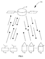
- the exemplary system 100 of FIG. 1 represents a satellite television broadcast system. It is contemplated, however, that the principles of the present invention may be applicable to other types of systems.
- the system 100 includes one or more geosynchronous satellites 10 each having one or more transponders for enabling the reception and transmission of digital signals.
- QPSK quadrature phase shift keyed
- the satellite 10 retransmits the received uplink signals as downlink signals for reception by a plurality of spatially distributed subscribers 12.
- the satellite 10 receives the uplink signals from the earth stations 11 in one frequency band, and transmits the downlink signals to the subscribers 12 in a different frequency band.
- the downlink signals represent digital television signals.
- each of the subscribers 12 is equipped with a satellite television signal receiver and one or more antennas capable of receiving and transmitting digital signals in one or more digital signal formats.
- each of the subscribers 12 is equipped with one or more antennas capable of receiving digital quadrature phase shift keyed (QPSK) signals, and transmitting digital spread spectrum signals.
- QPSK digital quadrature phase shift keyed
- the present invention advantageously provides a return channel for various functions without the need for a telephone line connection.
- functions include, but are not limited to, subscriber billing, internet connections, subscriber-to-subscriber communication (e.g., e-mail messages), advertisement feedback (e.g., impulse buys, requests for additional information, feedback regarding advertisement viewing/effectiveness, etc.), and subscriber initiated data downloads (e.g., games, utilities, software, system debugs, etc.).
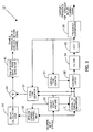
- FIG. 2 a schematic diagram of an exemplary circuit configuration suitable for generating a system time reference signal in accordance with principles of the present invention is shown.
- the exemplary circuit configuration of FIG. 2 may be provided at one or more earth stations such as the earth stations 11 shown in FIG. 1 .
- a frequency generator 20 generates a predetermined frequency standard. This frequency standard should be highly accurate, and does not have to be related to the bit clock of any digital modulation devices employed by the earth station 11.
- a counter 21 receives the frequency standard provided by the frequency generator 20 and performs a counting function in dependence upon the received frequency.
- the state of the counter 21 (i.e., its count) is used as a system time reference value to be distributed to the plurality of subscribers 12 via the satellite 10.
- a parallel to serial converter 22 receives a count value from the counter 21 and serially outputs the count value as a system time reference value in response to clock signals (CLK).
- a bit stream assembler 23 receives the system time reference value from the parallel to serial converter 22, and also receives satellite parameter (SP) data from the satellite 10.
- the satellite parameter (SP) data may include satellite position information (e.g., altitude, latitude, longitude, etc.) or orbital parameters from which such satellite position information can be calculated. In systems where multiple satellites are employed, orbital parameters may differ sufficiently to warrant multiple sets of satellite parameter (SP) data.
- the bit stream assembler 23 assembles its received inputs to generate return channel control data, which may be embodied as one or more packets of digital data.
- the return channel control data includes the system time reference value, the satellite parameter (SP) data, and may also include other data such as global or addressed messages.
- the return channel control data is transmitted by the earth station 11 as uplink data to the satellite 10, and retransmitted by the satellite 10 as downlink data to the plurality of subscribers 12.
- the return channel control data is utilized by a satellite television signal receiver to enable generation of a wireless return channel signal in accordance with principles of the present invention.
- FIG. 3 a schematic diagram of an exemplary circuit configuration suitable for enabling transmission of a wireless return channel signal in accordance with principles of the present invention is shown.
- the exemplary circuit configuration of FIG. 3 may be included in a satellite television signal receiver of a subscriber 12.
- the present invention advantageously establishes a time discipline for subscriber's return channel transmissions to assure that such transmissions are properly received.
- orthogonal codes such as spread spectrum signals may be employed to eliminate crosstalk among subscribers' return channel transmissions.
- the time alignment among subscribers' return channel transmissions must be closely controlled, as is achieved by the present invention.
- an incoming bit stream including the return channel control data is received as a downlink signal from the satellite 10.
- a packet state machine 30 parses the incoming bit stream and generates first and second control signals that enable identification and extraction of the return channel control data or a portion thereof.
- a serial to parallel converter 31 receives a first control signal from the packet state machine 30 that enables the serial to parallel converter 31 to extract the system time reference value portion of the return channel control data from the incoming bit stream.
- a subtract latch 32 receives the extracted system time reference value from the serial to parallel converter 31, and also receives a count value from a free running local time counter 33. The subtract latch 32 calculates and latches a difference value between the system time reference value and the count value provided from the local time counter 33.
- a filter 34 receives the difference value from the subtract latch 32 and performs a looping process to maintain the received difference value as a constant. That is, the filter 34 operates to maintain a constant difference between the received system time reference value and the count value provided from the local time counter 33.
- a voltage-controlled oscillator (VCO) 35 generates a signal having a frequency based on a voltage provided by the filter 34. As indicated in FIG. 3 , the voltage-controlled oscillator (VCO) 35 clocks the local time counter 33 with its outputs. In this manner, the filter 34 provides a voltage to the voltage-controlled oscillator (VCO) 35 to increase or decrease its frequency output, thereby increasing or decreasing the frequency at which the local time counter 33 is clocked. Portions of this circuitry may be implemented using digital or analog technology. For example, one skilled in the art will recognize that a digital numerically controlled sampled data oscillator may be used in place of the analog voltage-controlled oscillator (VCO) 35.
- a frequency synthesizer 36 also receives outputs from the voltage-controlled oscillator (VCO) 35, and synthesizes a carrier frequency for a wireless return channel signal in dependence upon those outputs.
- the carrier frequency generated by the frequency synthesizer 36 is approximately 17 GHz.
- the present invention advantageously utilizes a time reference to create a frequency reference suitable for enabling wireless transmission of a return channel signal.
- a second local time counter 37 is utilized to provide a stable time reference for scheduling return channel transmissions and framing data packets of the return channel signal. The second local time counter 37 is initialized each time a system time reference value is received, and is clocked by outputs from the voltage-controlled oscillator (VCO) 35.
- a return channel control unit 38 receives a second control signal from the packet state machine 30 that enables the return channel control unit 38 to extract the return channel control data from the incoming bit stream.
- a delay calculation unit 39 receives the extracted return channel control data from the return channel control unit 38 and uses that data to calculate another delay value corresponding to the particular subscriber 12. In particular, the delay value calculated by the delay calculation unit 39 is equal to: (the signal propagation delay time from the counter 21 of FIG.
- each of the foregoing delay times is the same for all subscribers 12, except for the signal propagation delay time from a transmitting antenna of the satellite 10 to a receiving antenna of a particular subscriber 12. Accordingly, the delay time calculated by the delay calculation unit 39 is different for each subscriber 12 due to differences in the signal propagation delay time from a transmitting antenna of the satellite 10 to a receiving antenna of a particular subscriber 12.
- the signal propagation delay time from a transmitting antenna of the satellite 10 to a receiving antenna of a particular subscriber 12 can be estimated from the distance between the two antennas. This distance can be calculated from the respective three-dimensional positions of the satellite 10 and the particular subscriber 12.
- a three-dimensional position for the satellite 10 can be calculated from the satellite parameter (SP) data included in the return channel control data.
- a three-dimensional position for the particular subscriber 12 can be calculated from subscriber information such as peak signal antenna pointing data, satellite data upon installation, address, zip code, telephone number, etc.
- An adder 40 adds the delay value calculated by the delay calculation unit 39 to a count value provided by the local time counter 37 to produce a sum value. This addition operation functions to synchronize each subscriber's 12 transmission of the wireless return channel signal.
- a transmission data frame generator 41 receives this sum value and enables transmission of the wireless return channel signal using the carrier frequency generated by the frequency synthesizer 36 in accordance with a time base represented by the received sum value. According to a preferred embodiment, the transmission data frame generator 41 enables transmission of the wireless return channel signal in accordance with a time base corresponding to the particular subscriber 12.
- This time base is such that if all of the subscribers 12 in the system 100 transmit their wireless return channel signal in accordance with the time base, all of the return channel signals will arrive at the satellite 10 at the same real time or within as narrow a time window as possible. In other words, the transmissions from the subscribers 12 will be time aligned (e.g., symbol boundaries are aligned) at the satellite 10 to the extent possible.
- This time base takes into account the different propagation delay times between the satellite 10 and each of the respective subscribers 12.
- the wireless return channel signal is transmitted from each of the subscribers 12 to the satellite 10 as a spread spectrum signal.
- the satellite 10 retransmits the return channel signal to earth for reception by a predetermined receiving entity such as a satellite television billing entity. This entity may be represented by the earth stations 11 in FIG. 1 . Since the transmissions from the subscribers 12 are time aligned at the satellite 10, the return channel signals are likewise received by the predetermined receiving entity in a time-aligned manner.
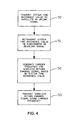
- FIG. 4 is a flow diagram illustrating a method for transmitting and receiving a wireless return channel signal in a satellite communications system having at least one satellite and a plurality of subscribers, according to an illustrative embodiment of the present invention. For illustrative purposes, the steps of FIG. 4 will be described in relation to the exemplary embodiments shown in FIGs. 1 through 3 .
- An earth station 11 generates a digital bit stream that includes a system time reference value and satellite parameter (SP) data, and transmits the same in an uplink signal to the satellite 10 (step 405).
- the earth station 11 may employ a circuit configuration such as that shown in FIG. 2 .
- the satellite 10 retransmits the digital bit stream including the system time reference value and SP data in a downlink signal for receipt by one or more of the subscribers 12 (step 410).
- a satellite television signal receiver of the subscribers 12 generates a precision frequency reference and a precision local clock from the received system time reference (step 415).
- the satellite television signal receiver may employ a circuit configuration such as that shown in FIG. 3 .
- the satellite television signal receiver of the subscribers 12 synthesizes a carrier frequency from the precision frequency reference for transmitting a wireless return channel signal (step 420).
- the satellite television signal receiver of the subscriber 12 calculates an offset for the precision local clock to compensate for a subscriber-to-satellite distance that varies for each of the subscribers 12 (step 425).
- the offset for the precision local clock may be calculated from a plurality of data including, for example, the SP data.
- a time base, particular to a given one of the subscribers 12, is derived from the (updated) precision local clock for use in controlling a time of transmission for that subscriber (step 430).
- the wireless return channel signal is transmitted from each of the subscribers 12 to the satellite 10, respectively in accordance with the time base particular to each of the subscribers and using the carrier frequency synthesized from the precision frequency reference (step 435).
- the wireless return channel signals are preferably transmitted using orthogonal spread spectrum codes. Since the subscribers 12 are geographically distributed, the subscribers 12 have to start their transmissions into the same time slot at different times (in accordance with their time base) to arrive at the satellite in time alignment. Each of the subscribers 12, in transmitting in the same time slot, will use a different orthogonal spread spectrum code.
- the present invention advantageously utilizes system time reference data to enable transmission of a return channel signal without requiring a telephone line connection.
- a time base is established which enables a time division multiplex transmission scheme (i.e., different subscribers are assigned different transmission time slots) sufficient to support return channel transmissions from a geographically distributed subscriber base using orthogonal codes
- the present invention has been described in relation to a television signal receiver, the invention is applicable to various systems, either with or without display devices, and phrases such as "satellite television signal receiver” or “television signal receiver” as used herein are intended to encompass various types of apparatuses and systems including, but not limited to, television sets or monitors that include a display device, and systems or apparatuses such as a set-top box, video tape recorder (VTR), digital versatile disk (DVD) player, video game box, or personal video recorder (PVR) that may not include display devices. While this invention has been described as having a preferred design, the present invention can be further modified within the scope of this disclosure. This application is therefore intended to cover any variations, uses, of adaptations of the invention using its general principles. Further, this application is intended to cover such departures from the present disclosure as come within known or customary practice in the art to which this invention pertains and which fall within the limits of the appended claims.
Landscapes
- Engineering & Computer Science (AREA)
- Signal Processing (AREA)
- Physics & Mathematics (AREA)
- Astronomy & Astrophysics (AREA)
- General Physics & Mathematics (AREA)
- Computer Networks & Wireless Communication (AREA)
- Multimedia (AREA)
- Aviation & Aerospace Engineering (AREA)
- Radio Relay Systems (AREA)
- Mobile Radio Communication Systems (AREA)
Claims (24)
- Verfahren zum Ermöglichen des drahtlosen Empfangs von Rückkanalsignalen in einem Satellitenkommunikationssystem mit mindestens einem Satelliten und mehreren Teilnehmern, wobei das Verfahren gekennzeichnet ist durch:Senden einer Systemzeitreferenz zum Festsetzen einer Präzisionsfrequenzreferenz, die auf der Systemzeitreferenz (50, 51) beruht, an die mehreren Teilnehmer; unddrahtloses Empfangen von Rückkanalsignalen von den mehreren Teilnehmern unter Verwendung einer Trägerfrequenz, die aus der aus der Systemzeitreferenz festgesetzten Präzisionsfrequenzreferenz synthetisiert worden ist (52, 53).
- Verfahren nach Anspruch 1, bei dem:die gesendete Systemzeitreferenz ferner zum jeweiligen Festsetzen von Zeitbasen daraus dient, wobei jede der Zeitbasen jeweils für einen der mehreren Teilnehmer spezifisch ist, unddrahtloses Empfangen der Rückkanalsignale von den mehreren Teilnehmern, das das drahtlose Empfangen der Rückkanalsignale jeweils in Übereinstimmung mit den Zeitbasen der mehreren Teilnehmer umfasst.
- Verfahren nach Anspruch 2, bei dem die Rückkanalsignale in einer zeitlich ausgerichteten Folge, die jeweils den Zeitbasen der mehreren Teilnehmer entspricht, drahtlos von den mehreren Teilnehmern empfangen werden.
- Verfahren nach Anspruch 2, bei dem die Zeitbasen für die zeitlich ausgerichteten Spreizspektrumcodes dienen, die durch die mehreren Teilnehmer in Sendungen an den mindestens einen Satelliten verwendet werden, um zeitsynchrone orthogonale Mehrbenutzer-Spreizspektrumsignale festzusetzen, und bei dem die Rückkanalsignale von den mehreren Teilnehmern als die zeitsynchronen orthogonalen Mehrbenutzer-Spreizspektrumsignale drahtlos empfangen werden.
- Verfahren nach Anspruch 2, bei dem die Rückkanalsignale von den mehreren Teilnehmern unter Verwendung von Sendezeitschlitzen, die einem globalen Zeitmultiplex-Mehrfachzugriffsschema (TDMA-Schema) entsprechen, drahtlos empfangen werden.
- Verfahren nach Anspruch 2, bei dem das Satellitenkommunikationssystem ferner mindestens eine bodengestützte Station aufweist und bei dem das Verfahren ferner den Schritt des anfänglichen Empfangens der Systemzeitreferenz von der mindestens einen bodengestützten Station umfasst.
- Verfahren nach Anspruch 2, das ferner den Schritt des drahtlosen Sendens der von den mehreren Teilnehmern empfangenen Rückkanalsignale an eine vorgegebene bodengestützte Empfangsentität umfasst.
- Verfahren nach Anspruch 7, bei dem die Rückkanalsignale in einer zeitlich ausgerichteten Folge drahtlos an die vorgegebene bodengestützte Empfangsentität gesendet werden.
- Verfahren nach Anspruch 1, bei dem das Senden der Systemzeitreferenz das Senden eines Zählerwerts umfasst.
- Verfahren nach Anspruch 1, bei dem:die Systemzeitreferenz auf einem Signal beruht und die Systemzeitreferenz zum Festsetzten einer Präzisionsfrequenzreferenz, die auf der Systemzeitreferenz beruht und die mit dem Signal synchronisiert ist, bei den mehreren Teilnehmern dient, unddie Rückkanalsignale eine Trägerfrequenz aufweisen, die durch die mehreren Teilnehmer aus der aus der Systemzeitreferenz festgesetzten Präzisionsfrequenzreferenz synthetisiert wird, wobei die Trägerfrequenz mit dem Signal synchronisiert wird.
- Verfahren zum Ermöglichen der drahtlosen Übertragung von Rückkanalsignalen in einem Satellitenkommunikationssystem mit mindestens einem Satelliten und mit mehreren Teilnehmern, wobei das Verfahren gekennzeichnet ist durch:Empfangen einer Systemzeitreferenz zum Festsetzen einer Präzisionsfrequenzreferenz, die auf der Systemzeitreferenz (51) beruht, von dem wenigsten einen Satelliten;Synthetisieren einer Trägerfrequenz aus der Präzisionsfrequenzreferenz, die aus der Systemzeitreferenz (52) festgesetzt worden ist; unddrahtloses Senden des Rückkanalsignals an den mindestens einen Satelliten unter Verwendung der Trägerfrequenz (53).
- Verfahren nach Anspruch 11, das ferner den folgenden Schritt umfasst:Festsetzen einer teilnehmerspezifischen Zeitbasis aus der empfangenen Systemzeitreferenz, undwobei das drahtlose Senden des Rückkanalsignals an den mindestens einen Satelliten das drahtlose Senden des Rückkanalsignals in Übereinstimmung mit der teilnehmerspezifischen Zeitbasis umfasst.
- Verfahren nach Anspruch 12, bei dem das Rückkanalsignal drahtlos an den mindestens einen Satelliten gesendet wird, um mit anderen der mehreren Teilnehmer eine zeitlich ausgerichtete Folge drahtloser Sendungen zu bilden.
- Verfahren nach Anspruch 13, bei dem die teilnehmerspezifische Zeitbasis für das jeweilige zeitliche Ausrichten eines Spreizspektrumcodes unter mehreren Spreizspektrumcodes, die durch die mehreren Teilnehmer in Sendungen an den mindestens einen Satelliten verwendet werden, um ein zeitsynchrones orthogonales Mehrbenutzer-Spreizspektrumsignal festzusetzen, dient und bei dem das Rückkanalsignal als das zeitsynchrone orthogonale Mehrbenutzer-Spreizspektrumsignal drahtlos gesendet wird.
- Verfahren nach Anspruch 13, bei dem der Schritt des drahtlosen Sendens orthogonale Spreizspektrumcodes nutzt, um die Mehrteilnehmerstörung zu minimieren.
- Verfahren nach Anspruch 12, bei dem das Rückkanalsignal unter Verwendung eines Sendezeitschlitzes, der einem globalen Zeitmultiplex-Mehrfachzugriffsschema (TDMA-Schema) entspricht, drahtlos gesendet wird.
- Verfahren nach Anspruch 12, das ferner den Schritt des Ableitens eines teilnehmerspezifischen lokalen Takts aus der Systemzeitreferenz umfasst und bei dem der Schritt des Festsetzens die teilnehmerspezifische Zeitbasis unter Verwendung des teilnehmerspezifischen lokalen Takts festsetzt.
- Verfahren nach Anspruch 17, das ferner den Schritt des Berechnens eines Versatzes für den teilnehmerspezifischen lokalen Takt umfasst, um eine veränderliche Teilnehmerentfernung zu dem mindestens einen Satelliten zu kompensieren.
- Verfahren nach Anspruch 18, das ferner den Schritt des Empfangens von Satellitenparameterdaten (SP-Daten) von dem mindestens einen Satelliten umfasst und bei dem der Schritt des Berechnens den Schritt des Berechnens des Versatzes für den teilnehmerspezifischen lokalen Takt mindestens unter Verwendung der SP-Daten umfasst.
- Verfahren nach Anspruch 11, bei dem:das Empfangen der Systemzeitreferenz das Empfangen eines Zählerwerts umfasst,das Verfahren ferner das Festsetzen der Präzisionsfrequenzreferenz umfasst, unddas Festsetzen der Präzisionsfrequenzreferenz umfasst:Vergleichen des empfangenen Zählerwerts mit einem Zählerwert, der durch einen Teilnehmer von den mehreren Teilnehmern erzeugt wird, undSteuern einer Frequenz eines Signals bei dem Teilnehmer anhand des Vergleichs des empfangenen Zählerwerts und des durch den Teilnehmer erzeugten Zählerwerts.
- Verfahren nach Anspruch 12, bei dem das Festsetzen der teilnehmerspezifischen Zeitbasis das Bestimmen einer Entfernung zwischen dem mindestens einen Satelliten und dem jeweiligen Teilnehmer umfasst.
- Verfahren nach Anspruch 11, bei dem:die Systemzeitreferenz auf einem Signal beruht und die Präzisionsfrequenzreferenz mit dem Signal synchronisiert wird, unddie Trägerfrequenz mit dem Signal synchronisiert wird.
- Vorrichtung zum Realisieren des Verfahrens gemäß einem der Ansprüche 1 bis 10, dadurch gekennzeichnet, dass die Vorrichtung umfasst:einen Sender zum Senden einer Systemzeitreferenz zum Festsetzen einer Präzisionsfrequenzreferenz, die auf der Systemzeitreferenz (10, 11) beruht, an die mehreren Teilnehmer; undeinen Empfänger zum drahtlosen Empfangen von Rückkanalsignalen von den mehreren Teilnehmern unter Verwendung einer Trägerfrequenz, die aus der aus der Systemzeitreferenz (10, 11) festgesetzten Präzisionsfrequenzreferenz synthetisiert wird.
- Vorrichtung zum Realisieren des Verfahrens nach einem der Ansprüche 11 bis 22, dadurch gekennzeichnet, dass die Vorrichtung umfasst:einen Empfänger zum Empfangen einer Systemzeitreferenz zum Festsetzen einer Präzisionsfrequenzreferenz, die auf der Systemzeitreferenz (12) beruht, von dem mindestens einen Satelliten;einen Frequenzsynthetisierer zum Synthetisieren einer Trägerfrequenz aus der aus der Systemzeitreferenz (36) festgesetzten Präzisionsfrequenzreferenz; undeinen Sender zum drahtlosen Senden des Rückkanalsignals an den mindestens einen Satelliten unter Verwendung der Trägerfrequenz (12).
Applications Claiming Priority (3)
| Application Number | Priority Date | Filing Date | Title |
|---|---|---|---|
| US38387902P | 2002-05-29 | 2002-05-29 | |
| US383879P | 2002-05-29 | ||
| PCT/US2003/016740 WO2003103300A2 (en) | 2002-05-29 | 2003-05-28 | Method and apparatus for enabling transmission of a wireless return channel signal in a satellite communications system |
Publications (3)
| Publication Number | Publication Date |
|---|---|
| EP1510018A2 EP1510018A2 (de) | 2005-03-02 |
| EP1510018A4 EP1510018A4 (de) | 2006-09-20 |
| EP1510018B1 true EP1510018B1 (de) | 2008-11-12 |
Family
ID=29711955
Family Applications (1)
| Application Number | Title | Priority Date | Filing Date |
|---|---|---|---|
| EP03736730A Expired - Lifetime EP1510018B1 (de) | 2002-05-29 | 2003-05-28 | Verfahren und vorrichtung zur ermöglichung der übertragung des signals eines drahtlosen rückkanals in einem satellitenkommunikationssystem |
Country Status (9)
| Country | Link |
|---|---|
| US (1) | US20050159103A1 (de) |
| EP (1) | EP1510018B1 (de) |
| JP (1) | JP2005528060A (de) |
| KR (1) | KR100977077B1 (de) |
| CN (1) | CN100544232C (de) |
| AU (1) | AU2003237265A1 (de) |
| DE (1) | DE60324672D1 (de) |
| MX (1) | MXPA04011778A (de) |
| WO (1) | WO2003103300A2 (de) |
Cited By (1)
| Publication number | Priority date | Publication date | Assignee | Title |
|---|---|---|---|---|
| DE102014105211A1 (de) * | 2014-04-11 | 2015-10-15 | Beckhoff Automation Gmbh | Verfahren zum Betreiben eines Teilnehmers eines Kommunikationsnetzwerks |
Families Citing this family (12)
| Publication number | Priority date | Publication date | Assignee | Title |
|---|---|---|---|---|
| EP1739450A1 (de) * | 2005-06-30 | 2007-01-03 | SES Astra S.A. | Verfahren und Vorrichtung zur Bestimmung des Standortes eines feststehenden Satellitenempfängers |
| US20070155318A1 (en) | 2006-01-04 | 2007-07-05 | Globalstar, Inc. | Satellite communication system employing a combination of time slots and orthogonal codes |
| US7711320B2 (en) * | 2006-01-04 | 2010-05-04 | Globalstar, Inc. | Satellite communication system for communicating packet data messages |
| US7630682B2 (en) * | 2006-01-04 | 2009-12-08 | Globalstar, Inc. | Satellite communication system employing a combination of time slots and orthogonal codes |
| US7792487B2 (en) * | 2006-01-04 | 2010-09-07 | Globalstar, Inc. | Satellite communication system for communicating packet data messages |
| EP2312767A1 (de) * | 2009-10-16 | 2011-04-20 | Astrium Limited | Anfrage von Rundfunkinhalt |
| WO2012149731A1 (zh) * | 2011-09-08 | 2012-11-08 | 华为技术有限公司 | 多用户接入的上行符号的同步方法、装置及系统 |
| FR2984641B1 (fr) * | 2011-12-15 | 2014-06-13 | Eutelsat Sa | Installation d'emission/reception de signaux radioelectriques |
| FR3019412B1 (fr) | 2014-04-01 | 2016-04-29 | Eutelsat Sa | Procede pour l'etablissement de liaisons radiofrequences |
| EP4142181A1 (de) | 2015-04-10 | 2023-03-01 | ViaSat Inc. | Bodenbasierte antennenstrahlformung für kommunikationen zwischen zugangsknoten und benutzerendgeräten, die durch ein relais, wie etwa einen satelliten, verbunden sind |
| US10187141B2 (en) | 2015-04-10 | 2019-01-22 | Viasat, Inc. | Cross-band system for end-to-end beamforming |
| CN106488546A (zh) * | 2015-08-24 | 2017-03-08 | 中兴通讯股份有限公司 | 时间调整的方法及装置 |
Family Cites Families (24)
| Publication number | Priority date | Publication date | Assignee | Title |
|---|---|---|---|---|
| DE1905532B2 (de) * | 1968-10-16 | 1971-06-03 | Schaltung zur synchronisierung der takt und oder traeger frequenz bei der impulsbuendelweisen uebertragung von digi talen signalen ueber nachrichten satelliten zwischen meh reren bodenstationen mittels zeitmultiplex | |
| US5041833A (en) * | 1988-03-28 | 1991-08-20 | Stanford Telecommunications, Inc. | Precise satellite ranging and timing system using pseudo-noise bandwidth synthesis |
| US5311550A (en) * | 1988-10-21 | 1994-05-10 | Thomson-Csf | Transmitter, transmission method and receiver |
| JP2915009B2 (ja) * | 1989-08-14 | 1999-07-05 | 株式会社日立製作所 | 回線制御方法 |
| US5036523A (en) * | 1989-10-03 | 1991-07-30 | Geostar Corporation | Automatic frequency control of satellite transmitted spread spectrum signals |
| US5379320A (en) * | 1993-03-11 | 1995-01-03 | Southern California Edison Company | Hitless ultra small aperture terminal satellite communication network |
| JPH0846605A (ja) * | 1994-07-27 | 1996-02-16 | Toshiba Corp | 多重化信号の位相同期回路 |
| JP3085511B2 (ja) * | 1994-11-24 | 2000-09-11 | 株式会社アドバンテスト | 基準周波数発生装置 |
| JPH08251094A (ja) * | 1995-03-15 | 1996-09-27 | Hitachi Ltd | 衛星通信システム及び方法 |
| US5822324A (en) * | 1995-03-16 | 1998-10-13 | Bell Atlantic Network Services, Inc. | Simulcasting digital video programs for broadcast and interactive services |
| US5790939A (en) * | 1995-06-29 | 1998-08-04 | Hughes Electronics Corporation | Method and system of frame timing synchronization in TDMA based mobile satellite communication system |
| US5841396A (en) * | 1996-03-08 | 1998-11-24 | Snaptrack, Inc. | GPS receiver utilizing a communication link |
| EP0779717A3 (de) | 1995-12-13 | 2000-08-02 | Nec Corporation | Verfahren und Anordnung zur Zeitsteuerung in einer Satellitenkommunikationsanordnung |
| JP2967738B2 (ja) * | 1995-12-13 | 1999-10-25 | 日本電気株式会社 | 衛星通信ネットワークにおけるtdmaタイミング制御システムとその方法 |
| DE19547604A1 (de) * | 1995-12-20 | 1997-06-26 | Sel Alcatel Ag | Set-Top-Box |
| US5910945A (en) * | 1996-04-30 | 1999-06-08 | Trw Inc. | Method and apparatus for synchronizing communications in a satellite based telecommunications system |
| FR2752352B1 (fr) * | 1996-08-12 | 1998-10-23 | Thomson Multimedia Sa | Systeme interactif de television par satellite |
| US5838669A (en) * | 1996-08-28 | 1998-11-17 | At&T Corp. | Method of synchronizing satellite switched CDMA communication system |
| IL135783A0 (en) * | 1997-10-20 | 2001-05-20 | Comsat Corp | A method for uplink power control for distributed satellite networks to compensate for rain fade |
| US6178195B1 (en) * | 1998-05-14 | 2001-01-23 | Motorola, Inc. | Method and apparatus for detecting spread spectrum signals using a signal from a secondary source |
| EP1030464B1 (de) * | 1999-02-19 | 2002-02-13 | Société Européenne des Satellites S.A. | Verfahren und Gerät zur Erzeugung einer Referenzfrequenz |
| US6993009B2 (en) * | 2000-03-10 | 2006-01-31 | Hughes Electronics Corporation | Method and apparatus for deriving uplink timing from asynchronous traffic across multiple transport streams |
| JP2002057613A (ja) * | 2000-08-09 | 2002-02-22 | Maspro Denkoh Corp | 衛星通信システム |
| JP2002152273A (ja) * | 2000-11-13 | 2002-05-24 | Nippon Telegr & Teleph Corp <Ntt> | 遅延ゆらぎ吸収方法およびパケット配置調整装置 |
-
2003
- 2003-05-28 EP EP03736730A patent/EP1510018B1/de not_active Expired - Lifetime
- 2003-05-28 DE DE60324672T patent/DE60324672D1/de not_active Expired - Lifetime
- 2003-05-28 CN CNB038123223A patent/CN100544232C/zh not_active Expired - Fee Related
- 2003-05-28 MX MXPA04011778A patent/MXPA04011778A/es active IP Right Grant
- 2003-05-28 KR KR1020047019085A patent/KR100977077B1/ko not_active Expired - Fee Related
- 2003-05-28 AU AU2003237265A patent/AU2003237265A1/en not_active Abandoned
- 2003-05-28 WO PCT/US2003/016740 patent/WO2003103300A2/en not_active Ceased
- 2003-05-28 US US10/515,008 patent/US20050159103A1/en not_active Abandoned
- 2003-05-28 JP JP2004510250A patent/JP2005528060A/ja active Pending
Cited By (2)
| Publication number | Priority date | Publication date | Assignee | Title |
|---|---|---|---|---|
| DE102014105211A1 (de) * | 2014-04-11 | 2015-10-15 | Beckhoff Automation Gmbh | Verfahren zum Betreiben eines Teilnehmers eines Kommunikationsnetzwerks |
| US9991981B2 (en) | 2014-04-11 | 2018-06-05 | Beckhoff Automation Gmbh | Method for operating a node of a communications network, a node and a communications network |
Also Published As
| Publication number | Publication date |
|---|---|
| MXPA04011778A (es) | 2005-07-05 |
| KR100977077B1 (ko) | 2010-08-19 |
| AU2003237265A1 (en) | 2003-12-19 |
| JP2005528060A (ja) | 2005-09-15 |
| WO2003103300A2 (en) | 2003-12-11 |
| KR20050004229A (ko) | 2005-01-12 |
| EP1510018A2 (de) | 2005-03-02 |
| DE60324672D1 (de) | 2008-12-24 |
| AU2003237265A8 (en) | 2003-12-19 |
| EP1510018A4 (de) | 2006-09-20 |
| US20050159103A1 (en) | 2005-07-21 |
| CN100544232C (zh) | 2009-09-23 |
| CN1656713A (zh) | 2005-08-17 |
| WO2003103300A3 (en) | 2004-01-08 |
Similar Documents
| Publication | Publication Date | Title |
|---|---|---|
| US6553040B2 (en) | Method and apparatus for upstream burst transmission synchronization in cable modems | |
| EP1738586B1 (de) | Verwürfelung des kopfteils der physischen schicht in satellitenausstrahlungssystemen | |
| KR100900531B1 (ko) | 단일 주파수 네트워크에서 전송 스트림을 동기시키기 위한시스템 및 방법 | |
| US20050159103A1 (en) | Method and apparatus for enabling transmission of a wireless return channel signal in a satellite communications system | |
| US20040141530A1 (en) | Method and apparatus for very high data rate satellite transmission | |
| KR100952571B1 (ko) | 신호 전송을 위한 스크램블링 코드들의 결정 방법 및 장치 | |
| US8699444B2 (en) | Broadcast system interference protection method and apparatus | |
| WO1999050985A1 (en) | Method and arrangement for synchronisation at a mobile radio communications system | |
| JPH09252278A (ja) | 無線同報通信システム | |
| JPH07245597A (ja) | スペクトラム拡散通信方法及び送受信装置 | |
| JP4383267B2 (ja) | 遅延設定用データ送信装置および地上デジタル放送波遅延時間測定調整装置 | |
| US7075950B2 (en) | Program clock reference correction method in a multiplexed burst mode downlink transmission in an integrated multispot satellite communication system | |
| US6684070B1 (en) | TDMA beacon for satellite system synchronization | |
| KR100542973B1 (ko) | 위성 디지털 멀티미디어 방송 시스템 에이 에서 시분할다중화 방식의 경로를 이용하는 장치 및 방법 | |
| JP7782268B2 (ja) | Ip伝送システム、iprf変換装置、rfip変換装置、ip伝送方法、iprf変換方法およびrfip変換方法 | |
| KR100605269B1 (ko) | 양방향 위성 시스템에서 위성 단말기의 데이터 송신 장치및 방법 | |
| Mishina et al. | Vacant TV channel reuse by extremely low power bidirectional SS using universal timing synchronization | |
| Evans | An uplinking technique for Eureka-147 satellite DAB | |
| Chung et al. | An overview of S‐DMB system and the testbed for satellite–mobile convergence services | |
| Ichiyoshi | A Proposal to China; Synch TDMA DSB Network for SINOSAT |
Legal Events
| Date | Code | Title | Description |
|---|---|---|---|
| PUAI | Public reference made under article 153(3) epc to a published international application that has entered the european phase |
Free format text: ORIGINAL CODE: 0009012 |
|
| 17P | Request for examination filed |
Effective date: 20041213 |
|
| AK | Designated contracting states |
Kind code of ref document: A2 Designated state(s): AT BE BG CH CY CZ DE DK EE ES FI FR GB GR HU IE IT LI LU MC NL PT RO SE SI SK TR |
|
| AX | Request for extension of the european patent |
Extension state: AL LT LV MK |
|
| DAX | Request for extension of the european patent (deleted) | ||
| RBV | Designated contracting states (corrected) |
Designated state(s): DE ES FR GB IT |
|
| RAP1 | Party data changed (applicant data changed or rights of an application transferred) |
Owner name: THOMSON LICENSING |
|
| A4 | Supplementary search report drawn up and despatched |
Effective date: 20060822 |
|
| 17Q | First examination report despatched |
Effective date: 20070201 |
|
| GRAP | Despatch of communication of intention to grant a patent |
Free format text: ORIGINAL CODE: EPIDOSNIGR1 |
|
| GRAS | Grant fee paid |
Free format text: ORIGINAL CODE: EPIDOSNIGR3 |
|
| GRAA | (expected) grant |
Free format text: ORIGINAL CODE: 0009210 |
|
| AK | Designated contracting states |
Kind code of ref document: B1 Designated state(s): DE ES FR GB IT |
|
| REG | Reference to a national code |
Ref country code: GB Ref legal event code: FG4D |
|
| REF | Corresponds to: |
Ref document number: 60324672 Country of ref document: DE Date of ref document: 20081224 Kind code of ref document: P |
|
| PG25 | Lapsed in a contracting state [announced via postgrant information from national office to epo] |
Ref country code: ES Free format text: LAPSE BECAUSE OF FAILURE TO SUBMIT A TRANSLATION OF THE DESCRIPTION OR TO PAY THE FEE WITHIN THE PRESCRIBED TIME-LIMIT Effective date: 20090223 |
|
| PLBE | No opposition filed within time limit |
Free format text: ORIGINAL CODE: 0009261 |
|
| STAA | Information on the status of an ep patent application or granted ep patent |
Free format text: STATUS: NO OPPOSITION FILED WITHIN TIME LIMIT |
|
| 26N | No opposition filed |
Effective date: 20090813 |
|
| PG25 | Lapsed in a contracting state [announced via postgrant information from national office to epo] |
Ref country code: IT Free format text: LAPSE BECAUSE OF FAILURE TO SUBMIT A TRANSLATION OF THE DESCRIPTION OR TO PAY THE FEE WITHIN THE PRESCRIBED TIME-LIMIT Effective date: 20081112 |
|
| REG | Reference to a national code |
Ref country code: FR Ref legal event code: PLFP Year of fee payment: 14 |
|
| REG | Reference to a national code |
Ref country code: FR Ref legal event code: PLFP Year of fee payment: 15 |
|
| REG | Reference to a national code |
Ref country code: DE Ref legal event code: R082 Ref document number: 60324672 Country of ref document: DE Representative=s name: HOFSTETTER, SCHURACK & PARTNER PATENT- UND REC, DE |
|
| REG | Reference to a national code |
Ref country code: FR Ref legal event code: PLFP Year of fee payment: 16 |
|
| PGFP | Annual fee paid to national office [announced via postgrant information from national office to epo] |
Ref country code: DE Payment date: 20180518 Year of fee payment: 16 |
|
| PGFP | Annual fee paid to national office [announced via postgrant information from national office to epo] |
Ref country code: FR Payment date: 20180523 Year of fee payment: 16 |
|
| PGFP | Annual fee paid to national office [announced via postgrant information from national office to epo] |
Ref country code: GB Payment date: 20180524 Year of fee payment: 16 |
|
| REG | Reference to a national code |
Ref country code: DE Ref legal event code: R119 Ref document number: 60324672 Country of ref document: DE |
|
| GBPC | Gb: european patent ceased through non-payment of renewal fee |
Effective date: 20190528 |
|
| PG25 | Lapsed in a contracting state [announced via postgrant information from national office to epo] |
Ref country code: GB Free format text: LAPSE BECAUSE OF NON-PAYMENT OF DUE FEES Effective date: 20190528 Ref country code: DE Free format text: LAPSE BECAUSE OF NON-PAYMENT OF DUE FEES Effective date: 20191203 |
|
| PG25 | Lapsed in a contracting state [announced via postgrant information from national office to epo] |
Ref country code: FR Free format text: LAPSE BECAUSE OF NON-PAYMENT OF DUE FEES Effective date: 20190531 |
|
| P01 | Opt-out of the competence of the unified patent court (upc) registered |
Effective date: 20230527 |