EP1510112B1 - Procede pour enrober de facon hermetique des composants optiques et composants optiques realises conformement a l'invention - Google Patents
Procede pour enrober de facon hermetique des composants optiques et composants optiques realises conformement a l'invention Download PDFInfo
- Publication number
- EP1510112B1 EP1510112B1 EP03724979A EP03724979A EP1510112B1 EP 1510112 B1 EP1510112 B1 EP 1510112B1 EP 03724979 A EP03724979 A EP 03724979A EP 03724979 A EP03724979 A EP 03724979A EP 1510112 B1 EP1510112 B1 EP 1510112B1
- Authority
- EP
- European Patent Office
- Prior art keywords
- glass
- housing
- glass solder
- pane
- housing body
- Prior art date
- Legal status (The legal status is an assumption and is not a legal conclusion. Google has not performed a legal analysis and makes no representation as to the accuracy of the status listed.)
- Expired - Lifetime
Links
Images

Classifications
-
- G—PHYSICS
- G02—OPTICS
- G02B—OPTICAL ELEMENTS, SYSTEMS OR APPARATUS
- G02B7/00—Mountings, adjusting means, or light-tight connections, for optical elements
-
- H—ELECTRICITY
- H01—ELECTRIC ELEMENTS
- H01S—DEVICES USING THE PROCESS OF LIGHT AMPLIFICATION BY STIMULATED EMISSION OF RADIATION [LASER] TO AMPLIFY OR GENERATE LIGHT; DEVICES USING STIMULATED EMISSION OF ELECTROMAGNETIC RADIATION IN WAVE RANGES OTHER THAN OPTICAL
- H01S5/00—Semiconductor lasers
- H01S5/02—Structural details or components not essential to laser action
- H01S5/022—Mountings; Housings
- H01S5/0225—Out-coupling of light
- H01S5/02257—Out-coupling of light using windows, e.g. specially adapted for back-reflecting light to a detector inside the housing
-
- H—ELECTRICITY
- H05—ELECTRIC TECHNIQUES NOT OTHERWISE PROVIDED FOR
- H05K—PRINTED CIRCUITS; CASINGS OR CONSTRUCTIONAL DETAILS OF ELECTRIC APPARATUS; MANUFACTURE OF ASSEMBLAGES OF ELECTRICAL COMPONENTS
- H05K5/00—Casings, cabinets or drawers for electric apparatus
- H05K5/06—Hermetically-sealed casings
-
- H—ELECTRICITY
- H01—ELECTRIC ELEMENTS
- H01S—DEVICES USING THE PROCESS OF LIGHT AMPLIFICATION BY STIMULATED EMISSION OF RADIATION [LASER] TO AMPLIFY OR GENERATE LIGHT; DEVICES USING STIMULATED EMISSION OF ELECTROMAGNETIC RADIATION IN WAVE RANGES OTHER THAN OPTICAL
- H01S5/00—Semiconductor lasers
- H01S5/02—Structural details or components not essential to laser action
- H01S5/022—Mountings; Housings
- H01S5/02208—Mountings; Housings characterised by the shape of the housings
- H01S5/02212—Can-type, e.g. TO-CAN housings with emission along or parallel to symmetry axis
Definitions
- the invention relates to a method for hermetic Housing of optical components, in particular for Production of a housing body or parts thereof, at which is a hermetic encapsulation of preferably optoelectronic components, and further relates according to the method produced optical components.
- Hermetically encapsulated enclosures are often used sensitive components such as lasers or photodiodes Protect environmental factors and help to create a ensure sufficient service life of these components.
- US-A-5 878 069 shows a method according to the Preamble of expression 1.
- Housing of this type often consist of a sleeve-shaped Metal body and one in the sleeve recordable and as Window serving glass pane.
- Such housing / optical caps was connected by Metal and glass component by means of a ring arranged glass solder, which as sintered molding was used ; see. DE-A-37 29 411). This had first before the actually joining the components of the glass solder molding in a separate operation in sintering technology getting produced. Subsequently, the molding was fit inserted in the sleeve-shaped metal component and with the covered by a round glass pane. It then follows the Smelting process, hermetically sealed at the sleeve and glass and are positively connected to each other.
- this technique encounters significant Feasibility limits, as soon as the glass window is no longer in Shape as a round disk but with a square contour, especially as a rectangle or in others, of a simple round geometry deviating forms is needed or the surface to be covered with glass solder is not horizontal or arched shaped.
- the corresponding glass solder moldings in Sintering technology is only of their form very limited and not with the required accuracy possible.
- the conventional method is because too much Lotmenge and the slipping of the Lotringes before the Melting or unsuitable during the soldering process.
- the invention is based on the object, a precise and for various housing geometries applicable method of to develop in the preamble of claim 1 mentioned type which is a reliable and inexpensive, preferably hermetic, connection between metal sleeve and glass pane allows.
- This task is performed using a procedure with the characteristics of Claim 1 and by a housing body with the features of Claim 19 solved.
- the glass solder as a moldable mass, in particular as a paste is applied and by at least one single energy input, in particular by burnout organic components, the glass solder pre-glazed and in fixed its shape has great advantages, since almost any shape, both two-dimensional plane as well vaulted forms provided with glass solder locally exactly defined can be.
- the housing element in the Housing assembly can then be heated by at least one partially hermetic connection between the housing element and Housing arrangement can be made.
- this includes Housing element a window, which consists of a glass sheet, and the Housing arrangement a housing cap.
- the application of the glass solder paste can advantageously at least partially on the glass pane and / or the housing cap be effected, whereby by a multiple order the height of the applied glass solder and also its quantity exactly is adjustable.
- the glass solder paste on a Antireflection or anti-scratch coating are applied, which on the surface of the housing element, in particular of the Window is arranged and can thereby high quality optical elements, such as lenses, ball lenses, Cylindrical lenses or optical filters such as DWDM filters or Grid to be mounted.
- the shape of the glass solder paste, in particular the cross section or the thickness of a applied route by adjusting the paste rheology is influenced and / or adjusted, because this is the Viscosity of the glass solder paste to the respective Mounting condition to be adjusted, where at lower Viscosities thinner solder cords and at higher viscosities thicker solder cords are produced. Furthermore, the bleeding the applied Lotschnur by their viscosity influenced or adapted to the assembly process.
- the glass solder paste is applied in a metered manner by means of a metering device, in particular a dispenser and preferably by means of a needle dispenser, surfaces running obliquely or in a complex manner in the space can be provided with glass solder reliably and in a precisely predefined manner.
- a metering device in particular a dispenser and preferably by means of a needle dispenser
- surfaces running obliquely or in a complex manner in the space can be provided with glass solder reliably and in a precisely predefined manner.
- cylindrical surfaces of housings or cylindrical lenses for example, in x- and / or y-direction scanning optical detection or writing systems are interconnected.
- the metering device is a ring or rectangular dispenser provided with a nozzle, because then a single, metered and preferably time / pressure-controlled application can be sufficient with the appropriate application geometry in order to completely apply the required quantity of glass solder.
- the Lotschnurdicke the paste-applied glass solder advantageously influenced and / or adjusted.
- Glass solder paste by means of stencil printing, in particular by means of Screen printing technique, the glass sheet is applied.
- the Manufacture can be designed inexpensively by first clicking on a mother disc which a variety of individual discs defines or includes a glass solder predefined Surface geometry is applied by a Energy input, in particular by burning organic Components the glass solder pre-glazed and in its shape is fixed, discs separated from the mother disc and the scattered glass with pre-glazed glass solder inserted into the housing cap and by thermal Influence a hermetic connection between glass pane and housing cap is made.
- the disc from the mother glass by Cracking and breaking or separated by laser cutting.
- housing body with a section of a pre-glazed glass solder independently tradable goods because then a customer whose own housing elements, such as For example, windows, lenses or filters in the Insert housing body and by heating or Energy input in this hermetically secure.
- housing elements such as For example, windows, lenses or filters in the Insert housing body and by heating or Energy input in this hermetically secure.
- a particularly preferred housing body comprises a metallic, sleeve-shaped cap, a housing element, which preferably serves as a window pane as well as between window and metal cap arranged glass solder.
- the invention uses as a link between
- a metal sleeve the housing body forms and about a glass sheet, which is a housing element forms, as a shapable mass applicable glass solder, preferably a glass solder paste.
- a shapable mass applicable glass solder preferably a glass solder paste.
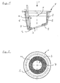
- Fig. 1 is a designated overall with 1 opto-cap during the manufacturing process.
- This opto cap 1 comprises a cylindrical or frusto-conical metal sleeve 2 with a passage opening 3 in the bottom surface. 4
- the passage opening 3 is suitable, for example, the Light of a laser beam or through optical elements like For example, lenses or filters affect pass through allow.
- a pasty glass solder 5 which in the present Example, the opening 3 completely surrounds as a soldering cord with applied to a needle dispenser.
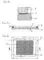
- Fig. 2 is a look in the in Figure 1 illustrated optical cap in the direction of arrow Y from Fig. 1 shows.
- the needle 6 emerges a needle dispenser into the interior of the metal sleeve 3 and carries at the lower end 7 the pasty Glass solder 5 on.
- Such needle dispensers are For example, from the company. Sieghard Schiller GmbH & Co. Kg., Sonnenbuehl, Germany, under the name Inline Dispensers distributed.
- Preferred thicknesses of applied glass solder paste start from about 500 microns Solder cord thickness, which is about the width of a plotted Line width correspond and are in their width not limited according to the invention.
- the process of applying includes a controller or Setting the travel speed of the dispenser needle at least during the application of the glass solder paste, the Pressure with which the glass solder paste emerges and the time How long the glass solder paste exits, so that hereby the Layer thickness of a jself one-time order is adjustable.
- the Needle 6 a tilt by an angle ⁇ of about 30 degrees +/- 3 degrees relative to the longitudinal axis X of the optical cap 1 and is along an oblique to the axis X ellipse moved parallel to the lower bottom surface 4. Also the Inclination of the bottom surface 4 is about 30 degrees relative to Longitudinal axis X.
- the needle 6 parallel to the longitudinal axis Y of in Fig. Represented optical cap are performed.
- increasing layers can be partially or complete multiple orders.
- the metal sleeve 2 After application of the glass solder, the metal sleeve 2 is combined heated with the glass solder layer 5 whereby the pasty Glaslot für 5 glazed and subsequently in their position is fixed. Here, organic components of the pasty glass solder removed.
- glass solder for example, all of the Fa. Schott glass used to sell glass solder,
- the glass solders with the designation 8465, 8467, 8468, 8470, 8471, 8472, 8474 and composite glass solders with the Number G017-002, G017-344, G017-339, G017-340, G017-383, G017-393, G017-334 and crystallizing glass solders such
- the glass solders 8587, 8593, 8596, 8597 and can as housing elements preferably glass window soldered each have a higher temperature resistance This means a higher temperature Tg than that corresponding soldering temperature of the glass solder used exhibit.
- a preferred glasses are special glasses with the designation D263, AF37, AF45, B270, Borofloat TM 33 and Borofloat40 of the Fa. Schott Glass, Mainz.
- the sleeve-shaped housing cap is preferably made a metallic alloy containing certain amounts of nickel contains, such as the alloy with the name NiFe47.
- optical caps can be parallel with Multi-needle dispensers are coated. It will be in their Location of aligned metal sleeves in multiple carriers arranged and with multiple needle systems in a single Coated operation.
- a depression 7 in the metal sleeve 3 causes in Interaction with a correspondingly shaped nose in one Carrier that an angular positioning of all Opto-caps become possible at the same time.
- a housing element such as For example, a glass pane 8, Fig. 10 in the mounted state is inserted in the sleeve 2 become.
- the glass sheet 8 is one of the above mentioned glasses of the company Schott Glass, Mainz.
- the Glass sheet 8 is made of the above-mentioned glass the designation D263 the company Schott glass, Mainz
- Dispensing the glass solder with a multi-needle system is preferably done with a dispenser head with 2, 4 or 8 Needles increasing the productivity of the order Number of needles multiplied.
- the offset or offset control of dispenser needles with each other can be done by a needle control station.
- the resulting needle position correction is performed by Realized independent adjustment axes, each Needle equipped with its own independent axis system is.
- Vorverglasens process along with the process of Soldering within a single rounding step be performed, which a corresponding longer duration has to do with the burning out of organic components enable. A subsequent cleaning of the case may arise, although not usually necessary, remove organic matter residues.
- round through holes 3 as well as glass panes 8 also rectangular, elliptical, oval, polygonal or depending on the application specific shaped openings 3 and glass panels 8 or optical Elements 8 are attached to the housing elements 2.
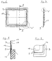
- Fig. 3 is a rectangular metallic carrier. 9 represented, on which a glass sheet 10 by means of a Glass solder layer 5 is attached.
- the invention differs from conventional methods, in which for the attachment of such rectangular Glass panes on metallic carriers so far metal layers had to be applied to the glass, which follow with a Metallot soldered to the carrier 9.
- the method according to the invention no longer requires one Such Metallevampfung, whereby this form of Fixing is very cost effective and time effective.
- the glass sheet 10 in housings optical CCD sensors, the glass sheet 10 an antireflection layer 11, 12th on one or both of their major surfaces.
- Fig. 5 is a plan view of the in Figs. 3 and Fig. 4 shows a rectangular optical cap illustrated is to recognize that the glass sheet 10 with finished housing For example, it can be arranged in front of a CCD array 13.
- CCD array 13 may also be micromechanical adjustable mirror systems, such as TV and Video projection devices or other elements with one encapsulated rectangular inlet or outlet window become.
- micromechanical adjustable mirror systems such as TV and Video projection devices or other elements with one encapsulated rectangular inlet or outlet window become.
- Fig. 6 shows another embodiment of a Housing arrangement according to the invention, in which the Glass sheet 10 but not the same side dimensions as the metallic carrier 9 has.
- the metallic carrier 9 has in this embodiment a web 14 which defines a bead 15 in which the glass solder layer 5 on a defined by the carrier 9 Pad is arranged. Through the web 14 and the bead 15 the glass solder is bounded laterally and can also be softer, more flowable glass solder with lower viscosity Find use.
- a metallic edge region 16 of the further holder for example, serve on an external module 17.
- an external module 17 for example, for the plant a Seal for resealable housings or windows Use find or can by further Attachment techniques such as gluing or soldering external enclosures are attached.
- the metallic carrier can thus form part of a complex shaped housing structure, especially a larger housing cap.
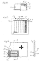
- FIG. 11 shows a mother plate 18, on which a plurality, preferably identically shaped window surfaces 19 to 24 is defined by the application of the glass solder layer 5.
- the glass solder layer 5 can indeed with Mehrnadeldispensern also be applied in this embodiment, however this is the technique of stencil printing, in particular the Screen printing preferred.
- the glass solder layer 5 can be applied to a one-piece mother plate 18 in a predefined form can be printed by heating a pre-glazing can be made and then along breaklines 25, 26 and 27, for example, by scribing and breaking the Mother plate 18 a separation of the discs or the window areas 19 to 24 performed become.
- the pre-glazing may be after or before the separation of the respective window areas 19 to 24 are made.
- a completely closed plumb line 26th be applied. This is done with the help of a dispenser 27, which has an annular nozzle 28 and preferably a time / pressure control device for the order process includes.
- the mother plate 18 shown in Fig. 11 also with a correspondingly shaped rectangular simple or multi-nozzle are printed stepwise, with a Stepper device each one offset preferably around the Width or length of a window surface of the windows 19 to 24 generated.
Landscapes
- Physics & Mathematics (AREA)
- General Physics & Mathematics (AREA)
- Optics & Photonics (AREA)
- Engineering & Computer Science (AREA)
- Microelectronics & Electronic Packaging (AREA)
- Electromagnetism (AREA)
- Condensed Matter Physics & Semiconductors (AREA)
- Joining Of Glass To Other Materials (AREA)
- Glass Compositions (AREA)
- Optical Couplings Of Light Guides (AREA)
- Semiconductor Lasers (AREA)
- Light Receiving Elements (AREA)
- Led Device Packages (AREA)
Claims (28)
- Procédé destiné à la fabrication d'un corps de boítier ou du moins de parties d'un corps de boítier, notamment à la fabrication d'un encapsulage de composants optoélectroniques, comportant
l'assemblage d'un élément de boítier avec un agencement de boítier de préférence métallique,
la mise en contact de l'élément de boítier et de l'agencement de boítier avec une brasure de verre,
caractérisé en ce que,
avant l'assemblage de l'élément de boítier et l'agencement de boítier, la brasure de verre est appliquée à l'état de masse pouvant être conformée, notamment à l'état de pâte,
en ce que par au moins un unique apport d'énergie, notamment par combustion de composés organiques, la brasure de verre est préalablement vitrifiée et fixée dans sa forme,
et en ce que, après l'insertion de l'élément de boítier dans l'agencement de boítier, une liaison hermétique est établie par chauffage entre l'élément de boítier et l'agencement de boítier, au moins par zones. - Procédé selon la revendication 1, caractérisé en ce que l'élément de boítier comporte une fenêtre qui est constituée d'une plaque de verre, et en ce que l'agencement de boítier comporte un couvercle de boítier.
- Procédé selon la revendication 1 ou 2, caractérisé en ce que l'application de la pâte de brasure de verre est effectuée, au moins par zones, sur la plaque de verre et/ou sur le couvercle de boítier.
- Procédé selon l'une des revendications 1, 2 ou 3, caractérisé en ce que l'application de la pâte de brasure de verre est effectuée dans le couvercle de boítier sur une surface d'appui disposée dans la zone périphérique.
- Procédé selon l'une des revendications 1 à 4, caractérisé en ce que l'application de la pâte de brasure de verre sur la surface d'appui prévue dans le couvercle de boítier est effectuée dans une zone de brasage, qui est délimitée du reste de la surface d'appui par une moulure.
- Procédé selon l'une des revendications 1 à 5, caractérisé en ce que l'application de la pâte de brasure de verre est effectuée sur une plaque de verre ou sur un couvercle de boítier angulaire, de préférence rectangulaire.
- Procédé selon l'une des revendications 1 à 6, caractérisé en ce que la pâte de brasure de verre est appliquée sur une couche antireflets ou antirayures, qui est disposée sur la surface de l'élément de boítier, notamment de la fenêtre.
- Procédé selon l'une des revendications 1 à 7, caractérisé en ce que la conformation de la pâte de brasure de verre, notamment la section transversale ou l'épaisseur d'un tronçon appliqué, est influencée et/ou réglée par le réglage de la rhéologie de la pâte.
- Procédé selon l'une des revendications 1 à 8, caractérisé en ce que la pâte de brasure de verre est appliquée de façon dosée au moyen d'un dispositif de dosage, notamment au moyen d'un dispensateur, et de préférence au moyen d'un dispensateur à aiguille.
- Procédé selon la revendication 9, caractérisé en ce que le dispositif de dosage est un dispensateur annulaire ou rectangulaire doté d'une buse.
- Procédé selon la revendication 9 ou 10, caractérisé en ce que l'épaisseur du cordon de la brasure de verre appliquée à l'état de pâte peut être influencée et/ou réglée par le choix de l'aiguille du dispensateur ou des dimensions de la buse.
- Procédé selon l'une des revendications 9 à 11, caractérisé en ce que la brasure de verre est exprimée de l'aiguille en étant commandée par une commande de pression / temps, et/ou en ce que la vitesse de déplacement de l'aiguille du dispensateur est régulée, au moins pendant l'application de la pâte de brasure de verre.
- Procédé selon l'une des revendications 1 à 7, caractérisé en ce que la pâte de brasure de verre est de préférence appliquée sur la plaque de verre par technique de sérigraphie.
- Procédé selon la revendication 13, caractérisé en ce que la conformation de la pâte de brasure de verre, notamment l'épaisseur du cordon de brasure, est influencée et/ou réglée par une application réitérée.
- Procédé selon la revendication 13 ou 14, caractérisé en ce que la conformation de la pâte de brasure de verre est influencée et/ou réglée par la géométrie du tamis et/ou d'un pochoir.
- Procédé selon l'une des revendications 13 à 15, caractérisé en ce qu'une brasure de verre à géométrie de surface prédéfinie est appliquée dans un premier temps sur une plaque mère, qui définit ou comporte une pluralité de plaques individuelles,
en ce que la brasure de verre est préalablement vitrifiée par un apport d'énergie, notamment par combustion de composés organiques, et fixée dans sa forme,
en ce que des plaques sont individualisées à partir de la plaque mère, et
en ce que la plaque individualisée avec la brasure de verre préalablement vitrifiée est insérée dans le couvercle de boítier, et
en ce qu'une liaison hermétique est établie par effet thermique entre la plaque de verre et le couvercle de boítier. - Procédé selon l'une des revendications 12 à 16, caractérisé en ce que la plaque est individualisée de la plaque de verre mère par entaille et rupture ou au moyen d'une découpe au laser.
- Procédé selon l'une des revendications 1 à 17, caractérisé en ce qu'un corps moulé en verre fritté et de la brasure pâteuse de verre sont appliqués sur le corps de boítier et/ou sur l'élément de boítier.
- Corps de boítier, caractérisé en ce qu'il est fabriqué avec un procédé selon l'une des revendications 1 à 18.
- Corps de boítier selon la revendication 19, caractérisé en ce qu'il comporte un tronçon d'une brasure de verre préalablement vitrifiée.
- Corps de boítier selon la revendication 19 ou 20, comportant un couvercle métallique en forme de douille, un élément de boítier qui est de préférence muni d'une plaque de verre servant de fenêtre, ainsi qu'une brasure de verre disposée entre la fenêtre et le couvercle métallique.
- Corps de boítier selon la revendication 21, caractérisé en ce que le corps de boítier comporte un couvercle d'optique pour l'encapsulage de composants optiques, tels que des lasers ou des photodiodes.
- Corps de boítier selon la revendication 22, comportant une douille métallique ronde ou rectangulaire et, sensiblement congruente à une face frontale intérieure de la douille métallique, une plaque de verre ronde ou rectangulaire qui est en contact avec la face frontale de la douille métallique à partir de la face intérieure de celle-ci, et
une brasure de verre appliquée sur la plaque de verre et/ou sur la douille métallique, qui est appliquée au moyen de dispensateurs ou de sérigraphie. - Corps de boítier selon la revendication 23, caractérisé en ce que la douille métallique possède en face frontale une surface d'appui intérieure périphérique, sur laquelle est disposée la pâte de brasure de verre.
- Corps de boítier selon la revendication 24, caractérisé en ce que la surface d'appui périphérique frontale comporte une moulure, qui délimite une zone de brasage prévue pour la brasure de verre par rapport au reste de la surface d'appui.
- Corps de boítier selon l'une des revendications 19 à 25, caractérisé en ce que le plan de la surface d'appui périphérique est incliné par rapport à un axe longitudinal du corps de boítier.
- Corps de boítier selon l'une des revendications 19 à 26, caractérisé en ce que la plaque de verre est dotée d'une couche antireflets et/ou antirayures, et est brasée sur la surface d'appui inclinée.
- Corps de boítier selon la revendication 21, caractérisé en ce que l'élément de boítier comporte un élément optique qui est une lentille, une lentille cylindrique ou une lentille sphérique.
Applications Claiming Priority (3)
| Application Number | Priority Date | Filing Date | Title |
|---|---|---|---|
| DE10224710 | 2002-06-03 | ||
| DE10224710A DE10224710B4 (de) | 2002-06-04 | 2002-06-04 | Verfahren zur hermetischen Gehäusung von optischen Bauelementen sowie verfahrensgemäß hergestellte optische Bauelemente |
| PCT/EP2003/003649 WO2003103358A1 (fr) | 2002-06-03 | 2003-04-09 | Procede pour enrober de façon hermetique des composants optiques et composants optiques realises conformement a l'invention |
Publications (3)
| Publication Number | Publication Date |
|---|---|
| EP1510112A1 EP1510112A1 (fr) | 2005-03-02 |
| EP1510112B1 true EP1510112B1 (fr) | 2005-12-21 |
| EP1510112B8 EP1510112B8 (fr) | 2006-04-05 |
Family
ID=29594244
Family Applications (1)
| Application Number | Title | Priority Date | Filing Date |
|---|---|---|---|
| EP03724979A Expired - Lifetime EP1510112B8 (fr) | 2002-06-04 | 2003-04-09 | Procede pour enrober de facon hermetique des composants optiques et composants optiques realises conformement a l'invention |
Country Status (10)
| Country | Link |
|---|---|
| US (1) | US7368758B2 (fr) |
| EP (1) | EP1510112B8 (fr) |
| JP (1) | JP2005531478A (fr) |
| KR (2) | KR20090007498A (fr) |
| CN (1) | CN1297183C (fr) |
| AT (1) | ATE313933T1 (fr) |
| AU (1) | AU2003227579A1 (fr) |
| CA (1) | CA2485498C (fr) |
| DE (2) | DE10224710B4 (fr) |
| WO (1) | WO2003103358A1 (fr) |
Families Citing this family (10)
| Publication number | Priority date | Publication date | Assignee | Title |
|---|---|---|---|---|
| DE10016628A1 (de) * | 2000-04-04 | 2001-10-18 | Schott Glas | Verfahren zum Herstellen von kleinen Dünnglasscheiben und größere Dünnglasscheibe als Halbfabrikat für dieses Herstellen |
| DE602004008116T2 (de) * | 2004-01-22 | 2008-04-24 | European Organisation For Nuclear Research Cern | Evakuierbarer flachplattensonnenkollektor |
| FR2894037B1 (fr) * | 2005-11-28 | 2007-12-28 | Alcatel Sa | Instrument optique comprenant une cavite d'entree dans laquelle est place un miroir |
| DE102006031358A1 (de) * | 2006-07-05 | 2008-01-17 | Schott Ag | Verfahren zur Gehäusung optischer oder optoelektronischer Bauteile, sowie verfahrensgemäß herstellbares optisches oder optoelektronisches Gehäuseelement |
| DE102007050002A1 (de) * | 2007-10-16 | 2009-04-23 | Fraunhofer-Gesellschaft zur Förderung der angewandten Forschung e.V. | Mikromechanisches Sensor- oder Aktorbauelement und Verfahren zur Herstellung von mikromechanischen Sensor- oder Aktorbauelementen |
| DE102013007703A1 (de) | 2013-05-03 | 2014-11-06 | Forschungszentrum Jülich GmbH | Verfahren zur Herstellung einer Glaslot-Gründichtung |
| DE102016215322A1 (de) | 2016-08-17 | 2018-02-22 | Robert Bosch Gmbh | Gehäuse und Verfahren zur Herstellung eines Gehäuses |
| DE102016215361A1 (de) | 2016-08-17 | 2018-02-22 | Robert Bosch Gmbh | Gehäuse und Verfahren zur Herstellung eines Gehäuses |
| JP6805081B2 (ja) | 2017-05-26 | 2020-12-23 | 新光電気工業株式会社 | 発光装置用蓋体 |
| CN109632875B (zh) * | 2018-12-29 | 2021-08-03 | 湖北航天技术研究院总体设计所 | 一种模拟抛罩气动加热光学头罩的热性能试验系统及方法 |
Family Cites Families (21)
| Publication number | Priority date | Publication date | Assignee | Title |
|---|---|---|---|---|
| DE1596849B2 (de) * | 1967-01-10 | 1973-06-14 | Jenaer Glaswerk Schott & Gen , 6500 Mainz | Verfahren zum herstellen von glasmetall-verschmelzungen mit einschmelzleitern aus reaktions- und sorptionsaktiven stoffen |
| US3983771A (en) * | 1975-11-28 | 1976-10-05 | Ppg Industries, Inc. | Apparatus for precise subdivision of glass sheets |
| NL7904283A (nl) * | 1979-05-31 | 1980-12-02 | Philips Nv | Koppelelement met een lichtbron en en lensvormig element. |
| DE3137685C2 (de) * | 1981-09-22 | 1983-11-03 | Siemens AG, 1000 Berlin und 8000 München | Leuchtdiode für Signalleuchten. |
| JPS5925284A (ja) * | 1982-08-03 | 1984-02-09 | Nec Corp | 光半導体装置 |
| DE3729411A1 (de) | 1987-09-03 | 1989-03-16 | Diehl Gmbh & Co | Optik fuer strahlungssensor |
| DE3742893A1 (de) * | 1987-12-17 | 1989-07-06 | Siemens Ag | Verfahren zur partiellen metallisierung von faserfoermigen festkoerpern, insbesondere lichtwellenleitern, und vorrichtung zur durchfuehrung des verfahrens |
| DE3830149A1 (de) | 1988-09-05 | 1990-03-15 | Siemens Ag | Optische linse zum hermetischen dichten verschliessen von gehaeusen |
| US5255333A (en) * | 1989-08-09 | 1993-10-19 | Siemens Aktiengesellschaft | Opto-electronic transducer arrangement having a lens-type optical coupling |
| US5140384A (en) * | 1990-06-14 | 1992-08-18 | Rohm Co., Ltd. | Semiconductor laser device mounted on a stem |
| US5274502A (en) * | 1991-10-31 | 1993-12-28 | Corning Incorporated | Molded lens with integral mount and method |
| US5323051A (en) * | 1991-12-16 | 1994-06-21 | Motorola, Inc. | Semiconductor wafer level package |
| JP3144279B2 (ja) * | 1995-09-18 | 2001-03-12 | 株式会社村田製作所 | センサ製造用パレット及び赤外線センサの製造方法 |
| KR100436467B1 (ko) | 1995-11-14 | 2004-08-09 | 로무 가부시키가이샤 | 반도체레이저및그제조방법 |
| JP3423855B2 (ja) * | 1996-04-26 | 2003-07-07 | 株式会社デンソー | 電子部品搭載用構造体および電子部品の実装方法 |
| JPH09307144A (ja) * | 1996-05-14 | 1997-11-28 | Matsushita Electric Ind Co Ltd | 発光素子及びその製造方法 |
| US6420205B1 (en) * | 1999-03-24 | 2002-07-16 | Kyocera Corporation | Method for producing package for housing photosemiconductor element |
| DE10192497D2 (de) * | 2000-06-21 | 2003-05-15 | Schott Glas | Verfahren zur Herstellung von Glassubstraten für elektronische Speichermedien |
| US6536958B2 (en) * | 2000-12-20 | 2003-03-25 | Triquint Technology Holding Co. | Optical device package with hermetically bonded fibers |
| AT5153U1 (de) * | 2001-03-22 | 2002-03-25 | Avl List Gmbh | Optischer sensor zur erfassung von verbrennungsvorgängen |
| US6627814B1 (en) * | 2002-03-22 | 2003-09-30 | David H. Stark | Hermetically sealed micro-device package with window |
-
2002
- 2002-06-04 DE DE10224710A patent/DE10224710B4/de not_active Expired - Lifetime
-
2003
- 2003-04-09 AU AU2003227579A patent/AU2003227579A1/en not_active Abandoned
- 2003-04-09 AT AT03724979T patent/ATE313933T1/de not_active IP Right Cessation
- 2003-04-09 CA CA2485498A patent/CA2485498C/fr not_active Expired - Lifetime
- 2003-04-09 KR KR1020087031341A patent/KR20090007498A/ko not_active Ceased
- 2003-04-09 DE DE50302009T patent/DE50302009D1/de not_active Expired - Fee Related
- 2003-04-09 CN CNB038129256A patent/CN1297183C/zh not_active Expired - Lifetime
- 2003-04-09 EP EP03724979A patent/EP1510112B8/fr not_active Expired - Lifetime
- 2003-04-09 KR KR1020047019778A patent/KR20050030898A/ko not_active Ceased
- 2003-04-09 WO PCT/EP2003/003649 patent/WO2003103358A1/fr not_active Ceased
- 2003-04-09 JP JP2004510299A patent/JP2005531478A/ja active Pending
- 2003-04-09 US US10/515,034 patent/US7368758B2/en not_active Expired - Lifetime
Also Published As
| Publication number | Publication date |
|---|---|
| CN1297183C (zh) | 2007-01-24 |
| JP2005531478A (ja) | 2005-10-20 |
| EP1510112A1 (fr) | 2005-03-02 |
| KR20050030898A (ko) | 2005-03-31 |
| WO2003103358A1 (fr) | 2003-12-11 |
| US7368758B2 (en) | 2008-05-06 |
| CA2485498A1 (fr) | 2003-12-11 |
| DE10224710A1 (de) | 2004-01-08 |
| DE10224710B4 (de) | 2005-12-08 |
| AU2003227579A1 (en) | 2003-12-19 |
| EP1510112B8 (fr) | 2006-04-05 |
| CN1659940A (zh) | 2005-08-24 |
| US20050224827A1 (en) | 2005-10-13 |
| KR20090007498A (ko) | 2009-01-16 |
| DE50302009D1 (de) | 2006-01-26 |
| CA2485498C (fr) | 2012-05-29 |
| ATE313933T1 (de) | 2006-01-15 |
Similar Documents
| Publication | Publication Date | Title |
|---|---|---|
| DE112009001347T5 (de) | Schmelzverbindungsprozess für Glas | |
| DE3138296C2 (fr) | ||
| EP1510112B1 (fr) | Procede pour enrober de facon hermetique des composants optiques et composants optiques realises conformement a l'invention | |
| DE69833957T2 (de) | Hochfeste berührungstafel und deren herstellungsverfahren | |
| DE102010062118B4 (de) | Herstellungsverfahren für eine Abdeckvorrichtung für ein mikro-opto-mechanisches Bauteil | |
| DE69412906T2 (de) | Glaspolyedern und Verfahren zu ihrer Herstellung | |
| DE112009001326T5 (de) | Schmelzverbindungsprozess für Glas | |
| WO2008006504A2 (fr) | Procédé de fabrication de composants optoélectroniques et produits fabriqués à l'aide desdits composants | |
| DE112004000581T5 (de) | Verfahren zum Schneiden von Glas | |
| EP0428575A1 (fr) | Procede pour produire des inscriptions sur des elements composites a l'aide de rayons laser et element composite ainsi obtenu | |
| DE102018111898B4 (de) | Verfahren zur Herstellung eines Gehäuses für ein optoelektronisches Bauelement | |
| EP2520394B1 (fr) | Dispositif et procédé d'enlèvement de bord et de rainurage de substrats revêtus utilisant deux sources laser agissant sur le même côté du substrat transparent revêtu | |
| EP4429999A1 (fr) | Ensemble relié hermétiquement | |
| DE19901623B4 (de) | Verfahren und Vorrichtung zur thermischen Verbindung von Anschlußflächen zweier Substrate | |
| DE2924068C2 (de) | Verfahren zur Herstellung koplanarer optoelektronischer Koppelelemente | |
| DE102016204228B4 (de) | Dispensierungsvorrichtung zur Glasdispensierung | |
| EP1607781B1 (fr) | Ensemble d'éléments microoptiques sur un substrat, méthode pour le réglage de cet ensemble, et système optique comportant un tel ensemble | |
| DE69027039T2 (de) | Geteilter schattenmaskenträgerrahmen und verfahren für eine farbkathodenstrahlröhre mit gespannter flachmaske | |
| EP0887118A2 (fr) | Procédé et dispositif pour réparer des petits défauts dans les couches de peintures | |
| EP0867418B1 (fr) | Procédé et dispositif pour la fabrication de structures de précision à grandes surfaces sur des feuilles de verre | |
| AT523200B1 (de) | Vorrichtung zur additiven fertigung | |
| EP0786326A1 (fr) | Procédé et dispositif pour la fabrication de lentilles optiques et feuilles lenticulaires | |
| DE102022103260A1 (de) | Laserbauelement | |
| WO2019214867A1 (fr) | Procédé de fabrication d'un dispositif micromécanique pourvu de fenêtres optiques inclinées et dispositif micromécanique correspondant | |
| EP4519201A1 (fr) | Procédé de production d'un élément de capuchon composite et élément de capuchon composite |
Legal Events
| Date | Code | Title | Description |
|---|---|---|---|
| PUAI | Public reference made under article 153(3) epc to a published international application that has entered the european phase |
Free format text: ORIGINAL CODE: 0009012 |
|
| 17P | Request for examination filed |
Effective date: 20041106 |
|
| AK | Designated contracting states |
Kind code of ref document: A1 Designated state(s): AT BE BG CH CY CZ DE DK EE ES FI FR GB GR HU IE IT LI LU MC NL PT RO SE SI SK TR |
|
| AX | Request for extension of the european patent |
Extension state: AL LT LV MK |
|
| GRAP | Despatch of communication of intention to grant a patent |
Free format text: ORIGINAL CODE: EPIDOSNIGR1 |
|
| GRAS | Grant fee paid |
Free format text: ORIGINAL CODE: EPIDOSNIGR3 |
|
| GRAA | (expected) grant |
Free format text: ORIGINAL CODE: 0009210 |
|
| RIN1 | Information on inventor provided before grant (corrected) |
Inventor name: SAUSENTHALER, EDELTRAUD Inventor name: MUND, DIETRICH Inventor name: MAYER, MARKUS Inventor name: SCHACHTLBAUER, KLAUS Inventor name: HAMMER, BERND Inventor name: HETTLER, ROBERT |
|
| AK | Designated contracting states |
Kind code of ref document: B1 Designated state(s): AT BE BG CH CY CZ DE DK EE ES FI FR GB GR HU IE IT LI LU MC NL PT RO SE SI SK TR |
|
| PG25 | Lapsed in a contracting state [announced via postgrant information from national office to epo] |
Ref country code: IT Free format text: LAPSE BECAUSE OF FAILURE TO SUBMIT A TRANSLATION OF THE DESCRIPTION OR TO PAY THE FEE WITHIN THE PRESCRIBED TIME-LIMIT;WARNING: LAPSES OF ITALIAN PATENTS WITH EFFECTIVE DATE BEFORE 2007 MAY HAVE OCCURRED AT ANY TIME BEFORE 2007. THE CORRECT EFFECTIVE DATE MAY BE DIFFERENT FROM THE ONE RECORDED. Effective date: 20051221 Ref country code: CZ Free format text: LAPSE BECAUSE OF FAILURE TO SUBMIT A TRANSLATION OF THE DESCRIPTION OR TO PAY THE FEE WITHIN THE PRESCRIBED TIME-LIMIT Effective date: 20051221 Ref country code: RO Free format text: LAPSE BECAUSE OF FAILURE TO SUBMIT A TRANSLATION OF THE DESCRIPTION OR TO PAY THE FEE WITHIN THE PRESCRIBED TIME-LIMIT Effective date: 20051221 Ref country code: SI Free format text: LAPSE BECAUSE OF FAILURE TO SUBMIT A TRANSLATION OF THE DESCRIPTION OR TO PAY THE FEE WITHIN THE PRESCRIBED TIME-LIMIT Effective date: 20051221 Ref country code: FI Free format text: LAPSE BECAUSE OF FAILURE TO SUBMIT A TRANSLATION OF THE DESCRIPTION OR TO PAY THE FEE WITHIN THE PRESCRIBED TIME-LIMIT Effective date: 20051221 Ref country code: NL Free format text: LAPSE BECAUSE OF FAILURE TO SUBMIT A TRANSLATION OF THE DESCRIPTION OR TO PAY THE FEE WITHIN THE PRESCRIBED TIME-LIMIT Effective date: 20051221 Ref country code: SK Free format text: LAPSE BECAUSE OF FAILURE TO SUBMIT A TRANSLATION OF THE DESCRIPTION OR TO PAY THE FEE WITHIN THE PRESCRIBED TIME-LIMIT Effective date: 20051221 Ref country code: IE Free format text: LAPSE BECAUSE OF FAILURE TO SUBMIT A TRANSLATION OF THE DESCRIPTION OR TO PAY THE FEE WITHIN THE PRESCRIBED TIME-LIMIT Effective date: 20051221 |
|
| REG | Reference to a national code |
Ref country code: GB Ref legal event code: FG4D Free format text: NOT ENGLISH |
|
| REG | Reference to a national code |
Ref country code: CH Ref legal event code: EP |
|
| GBT | Gb: translation of ep patent filed (gb section 77(6)(a)/1977) |
Effective date: 20051221 |
|
| REG | Reference to a national code |
Ref country code: IE Ref legal event code: FG4D Free format text: LANGUAGE OF EP DOCUMENT: GERMAN |
|
| REF | Corresponds to: |
Ref document number: 50302009 Country of ref document: DE Date of ref document: 20060126 Kind code of ref document: P |
|
| PG25 | Lapsed in a contracting state [announced via postgrant information from national office to epo] |
Ref country code: GR Free format text: LAPSE BECAUSE OF FAILURE TO SUBMIT A TRANSLATION OF THE DESCRIPTION OR TO PAY THE FEE WITHIN THE PRESCRIBED TIME-LIMIT Effective date: 20060321 Ref country code: BG Free format text: LAPSE BECAUSE OF FAILURE TO SUBMIT A TRANSLATION OF THE DESCRIPTION OR TO PAY THE FEE WITHIN THE PRESCRIBED TIME-LIMIT Effective date: 20060321 Ref country code: DK Free format text: LAPSE BECAUSE OF FAILURE TO SUBMIT A TRANSLATION OF THE DESCRIPTION OR TO PAY THE FEE WITHIN THE PRESCRIBED TIME-LIMIT Effective date: 20060321 Ref country code: SE Free format text: LAPSE BECAUSE OF FAILURE TO SUBMIT A TRANSLATION OF THE DESCRIPTION OR TO PAY THE FEE WITHIN THE PRESCRIBED TIME-LIMIT Effective date: 20060321 |
|
| PG25 | Lapsed in a contracting state [announced via postgrant information from national office to epo] |
Ref country code: ES Free format text: LAPSE BECAUSE OF FAILURE TO SUBMIT A TRANSLATION OF THE DESCRIPTION OR TO PAY THE FEE WITHIN THE PRESCRIBED TIME-LIMIT Effective date: 20060401 |
|
| PG25 | Lapsed in a contracting state [announced via postgrant information from national office to epo] |
Ref country code: AT Free format text: LAPSE BECAUSE OF NON-PAYMENT OF DUE FEES Effective date: 20060409 |
|
| PGFP | Annual fee paid to national office [announced via postgrant information from national office to epo] |
Ref country code: DE Payment date: 20060419 Year of fee payment: 4 |
|
| PG25 | Lapsed in a contracting state [announced via postgrant information from national office to epo] |
Ref country code: BE Free format text: LAPSE BECAUSE OF NON-PAYMENT OF DUE FEES Effective date: 20060430 Ref country code: MC Free format text: LAPSE BECAUSE OF NON-PAYMENT OF DUE FEES Effective date: 20060430 |
|
| PG25 | Lapsed in a contracting state [announced via postgrant information from national office to epo] |
Ref country code: PT Free format text: LAPSE BECAUSE OF FAILURE TO SUBMIT A TRANSLATION OF THE DESCRIPTION OR TO PAY THE FEE WITHIN THE PRESCRIBED TIME-LIMIT Effective date: 20060522 |
|
| NLV1 | Nl: lapsed or annulled due to failure to fulfill the requirements of art. 29p and 29m of the patents act | ||
| PG25 | Lapsed in a contracting state [announced via postgrant information from national office to epo] |
Ref country code: HU Free format text: LAPSE BECAUSE OF FAILURE TO SUBMIT A TRANSLATION OF THE DESCRIPTION OR TO PAY THE FEE WITHIN THE PRESCRIBED TIME-LIMIT Effective date: 20060622 |
|
| REG | Reference to a national code |
Ref country code: IE Ref legal event code: FD4D |
|
| ET | Fr: translation filed | ||
| PLBE | No opposition filed within time limit |
Free format text: ORIGINAL CODE: 0009261 |
|
| STAA | Information on the status of an ep patent application or granted ep patent |
Free format text: STATUS: NO OPPOSITION FILED WITHIN TIME LIMIT |
|
| 26N | No opposition filed |
Effective date: 20060922 |
|
| REG | Reference to a national code |
Ref country code: CH Ref legal event code: PL |
|
| BERE | Be: lapsed |
Owner name: SCHOTT A.G. Effective date: 20060430 |
|
| PG25 | Lapsed in a contracting state [announced via postgrant information from national office to epo] |
Ref country code: DE Free format text: LAPSE BECAUSE OF NON-PAYMENT OF DUE FEES Effective date: 20071101 |
|
| PG25 | Lapsed in a contracting state [announced via postgrant information from national office to epo] |
Ref country code: CH Free format text: LAPSE BECAUSE OF NON-PAYMENT OF DUE FEES Effective date: 20070430 Ref country code: LI Free format text: LAPSE BECAUSE OF NON-PAYMENT OF DUE FEES Effective date: 20070430 |
|
| PG25 | Lapsed in a contracting state [announced via postgrant information from national office to epo] |
Ref country code: EE Free format text: LAPSE BECAUSE OF FAILURE TO SUBMIT A TRANSLATION OF THE DESCRIPTION OR TO PAY THE FEE WITHIN THE PRESCRIBED TIME-LIMIT Effective date: 20051221 |
|
| PG25 | Lapsed in a contracting state [announced via postgrant information from national office to epo] |
Ref country code: LU Free format text: LAPSE BECAUSE OF NON-PAYMENT OF DUE FEES Effective date: 20060409 Ref country code: TR Free format text: LAPSE BECAUSE OF FAILURE TO SUBMIT A TRANSLATION OF THE DESCRIPTION OR TO PAY THE FEE WITHIN THE PRESCRIBED TIME-LIMIT Effective date: 20051221 |
|
| PG25 | Lapsed in a contracting state [announced via postgrant information from national office to epo] |
Ref country code: CY Free format text: LAPSE BECAUSE OF FAILURE TO SUBMIT A TRANSLATION OF THE DESCRIPTION OR TO PAY THE FEE WITHIN THE PRESCRIBED TIME-LIMIT Effective date: 20051221 |
|
| REG | Reference to a national code |
Ref country code: FR Ref legal event code: PLFP Year of fee payment: 14 |
|
| REG | Reference to a national code |
Ref country code: FR Ref legal event code: PLFP Year of fee payment: 15 |
|
| REG | Reference to a national code |
Ref country code: FR Ref legal event code: PLFP Year of fee payment: 16 |
|
| PGFP | Annual fee paid to national office [announced via postgrant information from national office to epo] |
Ref country code: GB Payment date: 20220420 Year of fee payment: 20 Ref country code: FR Payment date: 20220420 Year of fee payment: 20 |
|
| REG | Reference to a national code |
Ref country code: GB Ref legal event code: PE20 Expiry date: 20230408 |
|
| PG25 | Lapsed in a contracting state [announced via postgrant information from national office to epo] |
Ref country code: GB Free format text: LAPSE BECAUSE OF EXPIRATION OF PROTECTION Effective date: 20230408 |