EP1510173B1 - Appareil de mesure d'impédances intracardiaques - Google Patents
Appareil de mesure d'impédances intracardiaques Download PDFInfo
- Publication number
- EP1510173B1 EP1510173B1 EP04090233.0A EP04090233A EP1510173B1 EP 1510173 B1 EP1510173 B1 EP 1510173B1 EP 04090233 A EP04090233 A EP 04090233A EP 1510173 B1 EP1510173 B1 EP 1510173B1
- Authority
- EP
- European Patent Office
- Prior art keywords
- impedance
- values
- ventricular
- designed
- contractility
- Prior art date
- Legal status (The legal status is an assumption and is not a legal conclusion. Google has not performed a legal analysis and makes no representation as to the accuracy of the status listed.)
- Expired - Lifetime
Links
Images
Classifications
-
- A—HUMAN NECESSITIES
- A61—MEDICAL OR VETERINARY SCIENCE; HYGIENE
- A61B—DIAGNOSIS; SURGERY; IDENTIFICATION
- A61B5/00—Measuring for diagnostic purposes; Identification of persons
- A61B5/05—Detecting, measuring or recording for diagnosis by means of electric currents or magnetic fields; Measuring using microwaves or radio waves
- A61B5/053—Measuring electrical impedance or conductance of a portion of the body
- A61B5/0538—Measuring electrical impedance or conductance of a portion of the body invasively, e.g. using a catheter
-
- A—HUMAN NECESSITIES
- A61—MEDICAL OR VETERINARY SCIENCE; HYGIENE
- A61B—DIAGNOSIS; SURGERY; IDENTIFICATION
- A61B5/00—Measuring for diagnostic purposes; Identification of persons
- A61B5/02—Detecting, measuring or recording for evaluating the cardiovascular system, e.g. pulse, heart rate, blood pressure or blood flow
- A61B5/02028—Determining haemodynamic parameters not otherwise provided for, e.g. cardiac contractility or left ventricular ejection fraction
-
- A—HUMAN NECESSITIES
- A61—MEDICAL OR VETERINARY SCIENCE; HYGIENE
- A61B—DIAGNOSIS; SURGERY; IDENTIFICATION
- A61B5/00—Measuring for diagnostic purposes; Identification of persons
- A61B5/05—Detecting, measuring or recording for diagnosis by means of electric currents or magnetic fields; Measuring using microwaves or radio waves
- A61B5/053—Measuring electrical impedance or conductance of a portion of the body
- A61B5/0535—Impedance plethysmography
-
- A—HUMAN NECESSITIES
- A61—MEDICAL OR VETERINARY SCIENCE; HYGIENE
- A61N—ELECTROTHERAPY; MAGNETOTHERAPY; RADIATION THERAPY; ULTRASOUND THERAPY
- A61N1/00—Electrotherapy; Circuits therefor
- A61N1/18—Applying electric currents by contact electrodes
- A61N1/32—Applying electric currents by contact electrodes alternating or intermittent currents
- A61N1/36—Applying electric currents by contact electrodes alternating or intermittent currents for stimulation
- A61N1/362—Heart stimulators
- A61N1/365—Heart stimulators controlled by a physiological parameter, e.g. heart potential
- A61N1/36514—Heart stimulators controlled by a physiological parameter, e.g. heart potential controlled by a physiological quantity other than heart potential, e.g. blood pressure
- A61N1/36521—Heart stimulators controlled by a physiological parameter, e.g. heart potential controlled by a physiological quantity other than heart potential, e.g. blood pressure the parameter being derived from measurement of an electrical impedance
-
- A—HUMAN NECESSITIES
- A61—MEDICAL OR VETERINARY SCIENCE; HYGIENE
- A61B—DIAGNOSIS; SURGERY; IDENTIFICATION
- A61B5/00—Measuring for diagnostic purposes; Identification of persons
- A61B5/0002—Remote monitoring of patients using telemetry, e.g. transmission of vital signals via a communication network
- A61B5/0031—Implanted circuitry
-
- A—HUMAN NECESSITIES
- A61—MEDICAL OR VETERINARY SCIENCE; HYGIENE
- A61B—DIAGNOSIS; SURGERY; IDENTIFICATION
- A61B5/00—Measuring for diagnostic purposes; Identification of persons
- A61B5/72—Signal processing specially adapted for physiological signals or for diagnostic purposes
- A61B5/7271—Specific aspects of physiological measurement analysis
- A61B5/7285—Specific aspects of physiological measurement analysis for synchronizing or triggering a physiological measurement or image acquisition with a physiological event or waveform, e.g. an ECG signal
Definitions
- the invention relates to an implant with electrode lead terminals for connecting intracardiac and / or epicardial electrode leads, wherein the electrode lead terminals together have at least three electrical contacts, at least one of which is associated with a right ventricular electrode and another with a left ventricular electrode.
- the implant has an impedance measuring unit which has a current or voltage source and a measuring device for a corresponding voltage or current measurement, which are connected to the electrical contacts and optionally a housing electrode of the implant, resulting in a tri- or quadrupole impedance measuring arrangement ,
- Such implants are as pacemakers, for example from the WO 03/51457 , of the WO 00/78391 or the US 2001/0012953 , basically known.
- WO 2004/050177 A1 is prior art under Art. 54 (3) EPC and describes a pacemaker having a stimulation pulse generator for biventricular pacing of the heart, the pacing pulse generator having right ventricular electrodes for stimulating a right ventricle of the heart and left ventricular stimulating electrodes for left ventricle stimulation of the heart.
- the electrodes are connected to an impedance determination unit such that a tri- or quadrupole impedance measurement arrangement results.
- an impedance signal resulting from a chronological progression of the impedance measured values a minimum of the impedance measured values Zmin within a first time window Tmin and a maximum of the impedance measured values ZES within a second time window TES, wherein the first time window Tmin and the second time window TES become shorter are oriented as a respective cardiac cycle interval and relative to a ventricular event in a cardiac cycle.
- the evaluation unit determines the maximum of the second derivative Z "max and the time thereof in the cardiac cycle interval T" max and thus determines from the second derivative of the impedance signal a contractility quantity corresponding to a contractility of a heart.
- Such an implant allows advantageously by means of impedance measurement hemodynamic parameters such as stroke volume.
- Hemodynamic parameters are determined instantaneously by means of echocardiography, chest impedance cardiography, thermodilution catheters or invasive pressure measurements during electrophysiological examinations. These procedures require a high clinical effort.
- pacemakers are sometimes implanted to perform ventricular pressure measurements using a sensor integrated into a pacing lead. This means that special electrode leads are required for such a device.
- Hemodynamic parameters of the circulatory system in particular the stroke volume (SV), the end-diastolic volume (EDV), the end-systolic volume (ESV) or the contractility of the heart and the dimensions of the ventricle provide important information about the condition of the cardiovascular system.
- the electrotherapy of the heart with the help of implants can be improved by a sensor that detects hemodynamic and geometric variables.
- Continuous monitoring of patients can be achieved by telemetering hemodynamic or geometric data for homemonitoring purposes.
- the observation of the hemodynamic condition is essential, in particular the observation of the progression (or improvement) of the disease or the monitoring of the patient's condition in the context of resynchronization or drug therapy.
- the intracardiac impedance measuring device comprises an electrotherapeutic implant, for example an implantable pacemaker or cardioverter / defibrillator, which has a measuring device for determining an intracardiac impedance or an intracardiac impedance characteristic (impedance signal).
- the electrodes of the implant are preferably arranged in three or four chambers of the heart, so that the arrangement is also suitable for multi-chamber stimulation and / or defibrillation.
- At least one bipolar electrode should be able to be placed in the right ventricle (RV) and a second bipolar electrode near the left ventricle (LV), either by placement in a lateral vein branching from the coronary sinus or at the epicardium.
- the left ventricular electrode is thus a coronary sinus electrode or an epicardial electrode.
- the first and second time windows are shorter than a respective cardiac cycle interval and relative to a ventricular event in one Heart cycle oriented.
- a first time window begins at a first start time (X1) before the respective ventricular event and ends at a first end time (X2) after this ventricular event, while a second time interval begins at a second start time (Y1) after that ventricular event second end time (Y2) after the ventricular event ends.
- the evaluation unit is preferably designed to determine a beat impedance (SZ) representing a stroke volume from a difference between the end-diastolic impedance (EDZ) and the end-systolic impedance (ESZ).
- SZ beat impedance
- EF ejection fraction
- SZ impact impedance
- EDZ end-diastolic impedance
- ESZ end-diastolic impedance
- EDC end-diastolic conductivity
- the evaluation unit is designed to determine an impedance signal resulting from a temporal course of the impedance measured values and to determine a contractility quantity representing a contractility of a heart from the first or second derivative of the impedance signal.
- hemodynamic parameters are of particular interest to the physician.
- any type of implant is advantageous with which interesting hemodynamic parameters can be determined by means of impedance measurement.
- the implant preferably has a memory for one or more of the values of impact impedance, EF size, or contractility.
- the evaluation unit is preferably designed to store the values for the impact impedance, the end-diastolic impedance (EDZ), the EF size and / or the contractility at regularly recurring storage instants.
- the evaluation unit is designed to form average values for the impact impedance, the end-diastolic impedance (EDZ), the EF size and / or the contractility for a period between two successive storage times and to store one or more of these average values ,
- the evaluation unit is preferably designed to determine from the temporal development of the impact impedance, the end-diastolic impedance (EDZ), the EF size or the contractility a respective trend value for one or more of these variables. These trend values are also preferably stored at a respective memory time by the evaluation unit in the memory.
- the implant preferably has a telemetry unit, which comprises at least one telemetry transmitter and is connected to the memory and designed to query or at regular transmission times values for impact impedance, end-diastolic impedance (EDC), EF size, contractility or one or more Send mean or trend values to an external device.
- a telemetry unit which comprises at least one telemetry transmitter and is connected to the memory and designed to query or at regular transmission times values for impact impedance, end-diastolic impedance (EDC), EF size, contractility or one or more Send mean or trend values to an external device.
- EDC end-diastolic impedance
- the implant preferably has all the known and advantageous features of a cardiac pacemaker, cardioverter and / or defibrillator. These features include, in particular, at least one ventricular or an atrial stimulation unit and a control unit with which stimulation variables, such as, for example, the stimulation pulse strength, a stimulation frequency or the like, can be set.
- stimulation variables such as, for example, the stimulation pulse strength, a stimulation frequency or the like.
- Such an implant is preferably designed as a rate-variable pacemaker having a sensor for the physiological needs of a patient, with the help of which the stimulation rate is automatically adapted to the physiological needs of a patient through the implant.
- the implant has an evaluation unit which is designed to determine the changes in the left ventricular diameter.
- the evaluation unit can also be designed to determine hemodynamic parameters of other heart chambers via impedance measurement.
- a quadrupole impedance measuring arrangement with two electrodes in the right ventricle for current injection and two further electrodes in the coronary sinus associated with the left ventricle is particularly advantageous and immune to interference for the measurement of a voltage resulting from the injected current.
- an implant is particularly preferred which has a quadrupole impedance measuring arrangement which is designed for connection to two right-ventricular electrodes for current injection and two left-ventricular electrodes arranged in a lateral vein branching off from the coronary sinus for measuring the voltage resulting from the current fed in
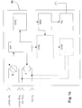
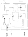
- FIGS. 1a and 1b show a schematic representation of an implant 10 or 10 'with an impedance measuring arrangement having a current source I and a voltage measuring unit U and impedance determining unit IMP.
- the voltage measuring unit U is in the embodiment in FIG. 1a with a left ventricular tip electrode arranged in a lateral vein branching off from the coronary sinus and a left ventricular ring electrode also arranged in a lateral vein branching off from the coronary sinus.
- the power supply unit I is connected to a right-ventricular tip and to a right-ventricular ring electrode - or more precisely to contacts for the connection of these electrodes.
- FIG. 1b is the voltage measuring unit U on the one hand as in Fig. 1a with left ventricular tip electrode and divergent from Fig. 1a on the other hand connected to the implant housing as a fourth electrode.
- the impedance determination unit IMP is connected to both the power supply unit I and the voltage measuring unit U for the impedance determination.
- the respectively determined impedance value is relayed by the impedance determination unit IMP to an evaluation unit EVAL.
- the evaluation unit EVAL determines in the manner described below from the values determined by the impedance determination unit IMP an end-diastolic impedance EDZ and an end-systolic impedance ESZ.
- EVAL ejection fraction
- the evaluation unit EVAL is further configured to provide mean values for the impact impedance, the EF size or the contractility for a respective one between two storage times lying period and to store these averages also in the memory.
- evaluation unit EVAL is designed to determine trends for the variables determined by the evaluation unit EVAL and to store corresponding trend values in the memory MEM.
- the memory MEM is connected to a telemetry unit TEL, which is designed such that the values respectively stored in the memory are emitted by the telemetry unit by means of a transmitting unit assigned to the telemetry unit at a regularly recurring transmission time such that the corresponding values are from an external device received and, for example, to a service center, a doctor or the like can be forwarded.
- TEL telemetry unit
- the stimulation unit SDIM is a right ventricular stimulation unit and thus connected to the connection for the right ventricular ring and the right ventricular tip electrode.
- the impedance measuring unit injects a subliminal current between two electrodes of the electrode leads connected to the implant and / or the implant housing.
- the current is in the form of biphasic pulses of constant amplitude.
- the current-induced voltage drop (the voltage) is measured across another pair of electrodes of the available electrodes.
- the measured voltage is proportional to the impedance of the tissue, which is in the measuring range.
- the current-injecting electrodes and the electrodes for voltage measurement may be the same electrodes.
- the measured voltage is first amplified and filtered by a programmable filter arrangement before being analog / digital converted.
- the programmable filter may be a low pass filter, a high pass filter or a band pass filter. In the embodiment described below, the filter is a low-pass filter.
- the measuring electrode arrangement is preferably quadrupolar, as explained above, in order in particular to detect changes in the diameter of the ventricle by means of impedance measurement. Accordingly, the current is injected via two electrodes and the voltage is measured via two other electrodes, which are different from the current-injecting electrodes.
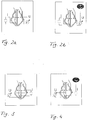
- the impedance signal measured with these configurations is cubically dependent on the distance between the two electrode leads.
- Z the impedance
- d the distance between the electrode lines.
- the reciprocal of the impedance is an indirect measure of the left ventricular volume because the left ventricular volume is approximately proportional to the third Potency of left ventricular diameter is. This is based on the assumption that the distance a between the two electrodes of a current-feeding dipole is very much smaller than the distance d of the voltage-measuring electrode (n) from the current-feeding dipole.
- the reciprocal of the impedance corresponds to the distance between the electrode lines if, as provided in configurations 3 and 4, a is much smaller than d.
- the evaluation of the impedance signal is carried out by the evaluation unit in the implant, which is connected to the measuring unit.
- the evaluation unit is designed to derive parameters from the measured impedance signal, in particular the temporal course of the impedance Z f (t), which depends on the end-diastolic and end-systolic diameter of the ventricle and thus on the end-diastolic volume (EDV), on the end-systolic volume (ESV) and on the Stroke volume (SV) of the corresponding chamber.
- the evaluation applies relative values of these variables and not their absolute values.
- the general idea underlying the determination of relative volume is based on the differences in the distances between right ventricular and left ventricular electrode leads during a contraction cycle.
- the ventricle expands during diastole and reaches its maximum diameter at the end of this phase. Accordingly, the impedance at the end of the diastole is minimal because the distance between the two electrode leads is maximum.
- the end-diastolic impedance is also referred to below as EDZ.
- the impedance at the end of the systole is maximal because the distance between the electrode leads is minimal due to the contraction of the ventricle.
- the corresponding end-systolic impedance is also referred to below as ESZ.
- the impact impedance SZ is proportional to the stroke volume SV of the ventricle.
- the conductivity of the blood is about 1.5 to 2 higher than the conductivity of the myocardium.
- the amount of blood in the measurement area is maximal during the end-diastolic phase and minimal during the end-systolic phase. This effect contributes to the impedance changes caused by the alternating ventricular diameter.
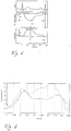
- FIG. 6 an example of a measured impedance signal is shown.
- 0 ms here corresponds to the point 50 ms before the R wave of the right ventricular intracardiac electrocardiogram in the case of a stimulus.
- the first maximum does not occur at the end of the systole, but is due to other influences. It should therefore not be within the systolic time window.
- FIG. 6 two examples are drawn.
- the solid line corresponds to the resting state of a patient and the dashed line corresponds to the state of physical exertion.
- the physical exertion leads to an increased stroke volume and thus to an end-of-systolic impedance increased to 12 ⁇ .
- the impedance signal may also be evaluated by calculating the first and second derivatives.
- the maximum values (possibly within a given time window) of the derivative of the inverse of the impedance correlate with the contractility of the ventricle.
- the signal evaluation is carried out separately for the resting state and the load state of the patient as part of a long-term monitoring.
- sleep state and load state are distinguished by means of an accelerometer, which is integrated in a preferred embodiment in the implant.
- the accelerometer generates an acceleration signal corresponding to the acceleration of the accelerometer. If the acceleration signal as an output signal of the accelerometer exceeds a predetermined threshold value for a predetermined period of time, this is regarded as a load condition. If the amplitude of the acceleration signal for a predetermined period of time below remains the threshold value, this is interpreted as the resting state of the patient.
- EF SV / EDV
- contractility can be monitored to determine the hemodynamic condition of a patient who To observe the effect of a resynchronization therapy or drug treatment or to determine and optimize certain operating parameter settings of an implant.
- the left ventricular diameter can be observed to detect, for example, changes in ventricular dimensions in patients with dilated or hypertrophic cardiomyopathy.
Landscapes
- Health & Medical Sciences (AREA)
- Life Sciences & Earth Sciences (AREA)
- Cardiology (AREA)
- Heart & Thoracic Surgery (AREA)
- Public Health (AREA)
- Animal Behavior & Ethology (AREA)
- Veterinary Medicine (AREA)
- Engineering & Computer Science (AREA)
- Biomedical Technology (AREA)
- Biophysics (AREA)
- General Health & Medical Sciences (AREA)
- Physics & Mathematics (AREA)
- Surgery (AREA)
- Molecular Biology (AREA)
- Medical Informatics (AREA)
- Pathology (AREA)
- Nuclear Medicine, Radiotherapy & Molecular Imaging (AREA)
- Radiology & Medical Imaging (AREA)
- Physiology (AREA)
- Hematology (AREA)
- Electrotherapy Devices (AREA)
- Measurement And Recording Of Electrical Phenomena And Electrical Characteristics Of The Living Body (AREA)
Claims (11)
- Implant avec des connexions de lignes d'électrode pour la connexion de lignes d'électrodes intracardiaques et/ou épicardiaques, où les connexions de lignes d'électrode présentent ensemble au moins trois contacts électriques, parmi lesquels au moins un est associé à une électrode du ventricule droit et un autre est associé à une électrode du ventricule gauche, avec une unité de détermination d'impédance (IMP) qui présente une source de courant ou de tension (I) et un dispositif de mesure (U) pour la mesure correspondante d'une tension, respectivement d'un courant, qui est relié avec les contacts électriques et éventuellement une électrode de boîtier de l'implant de telle manière qu'il en résulte un ensemble de mesure d'impédance tri ou quadripolaire qui comprend exclusivement des électrodes ventriculaires et en outre éventuellement l'électrode de boîtier, où l'ensemble de mesure d'impédance délivre des valeurs de mesure d'impédance et est relié avec une unité d'exploitation (EVAL) et l'unité d'exploitation (EVAL) est conçue pour déterminer un minimum des valeurs de mesure d'impédance dans une première fenêtre temporelle sous la forme d'une impédance diastolique finale (EDZ) et un maximum des valeurs de mesure d'impédance dans une deuxième fenêtre temporelle sous la forme d'une impédance systolique finale (ESZ) ou pour constituer une conductivité diastolique finale (EDC) en tant que valeur de reconnaissance de l'impédance diastolique finale (EDZ) et une conductivité systolique finale (ESC) en tant que valeur de reconnaissance de l'impédance systolique finale (ESZ), où les première et deuxième fenêtres temporelles sont plus courtes que l'intervalle du cycle cardiaque correspondant et orientées par rapport à un évènement ventriculaire dans un cycle cardiaque, et que l'unité d'exploitation est en outre conçue pour déterminer un signal d'impédance provenant d'une évolution dans le temps des valeurs de mesure d'impédance et pour déterminer à partir d'une première ou d'une deuxième dérivation du signal d'impédance une taille de contractilité correspondant à une contractilité d'un coeur, où la première fenêtre temporelle commence à un premier instant de début (x1) avant l'évènement ventriculaire en question et termine à un premier instant de fin (x2) après cet évènement ventriculaire, tandis que le deuxième intervalle temporel, commence à un deuxième instant de début (y1) après cet évènement ventriculaire et termine à un deuxième instant de fin (y2) après l'évènement ventriculaire.
- Implant selon la revendication 1,
caractérisé en ce que l'unité d'exploitation (EVAL) est conçue pour déterminer une impédance de battement (SZ) représentant un volume de battement à partir d'une différence entre l'impédance diastolique finale (EDZ) et l'impédance systolique finale (ASZ). - Implant selon la revendication 2,
caractérisé en ce que l'unité d'exploitation est conçue pour déterminer une grandeur EF représentant une fraction d'éjection (EF) à partir de l'impédance de battement (SZ) et de l'impédance diastolique finale (EDZ). - Implant selon l'une des revendications 1 à 3,
caractérisé par une mémoire (MEM) pour des valeurs pour l'impédance de battement et/ou la grandeur EF et/ou la contractilité et/ou les autres valeurs d'impédance et de conductivité des revendications précédentes. - Implant selon la revendication 4,
caractérisé en ce que l'unité d'exploitation (EVAL) est conçue pour stocker des valeurs pour l'impédance de battement et/ou la grandeur EF et/ou la contractilité à des instants de mémorisation se renouvelant régulièrement. - Implant selon la revendication 5,
caractérisé en ce que l'unité d'exploitation (EVAL) est conçue pour former des valeurs moyennes pour l'impédance de battement et/ou la grandeur EF et/ou la contractilité pour une durée entre deux instants de mémorisation se succédant et pour stocker la ou les valeurs moyennes. - Implant selon l'une des revendications 1 à 3,
caractérisé en ce que l'unité d'exploitation est conçue pour déterminer une valeur de tendance pour l'impédance de battement et/ou la grandeur EF et/ou la contractilité à partir de l'évolution dans le temps de l'impédance de battement et/ou de la grandeur EF et/ou de la contractilité. - Implant selon la revendication 7,
caractérisé en ce que l'unité d'exploitation (EVAL) est conçue pour stocker la ou les valeurs de tendance à un instant de mémorisation donné dans la mémoire. - Implant selon la revendication 4,
caractérisé par une unité de télémétrie (TEL) qui comprend au moins un émetteur de télémétrie et est reliée, ainsi que conçue, avec la mémoire pour émettre des valeurs pour l'impédance de battement et/ou la grandeur EF et/ou la contractilité et/ou une ou plusieurs valeurs moyennes ou de tendance sur demande à des instants d'émission réguliers vers un appareil externe. - Implant selon l'une des revendications 1 et 9,
caractérisé par au moins une unité de commande (CTRL) et une unité de stimulation (STIM), avec laquelle générer des impulsions de stimulation, de cardioversion et ou de défibrillation et délivrer à au moins une des connexions de ligne d'électrode. - Implant selon l'une des revendications 1 à 10,
caractérisé par un ensemble de mesure d'impédance quadripolaire qui est conçu pour la connexion à deux électrodes au ventricule droit pour l'alimentation en courant et à deux électrodes au ventricule gauche disposées dans le sinus coronaire pour la mesure de la tension résultant du courant introduit.
Applications Claiming Priority (4)
| Application Number | Priority Date | Filing Date | Title |
|---|---|---|---|
| DE10340894 | 2003-09-01 | ||
| DE10340894 | 2003-09-01 | ||
| DE10361143A DE10361143A1 (de) | 2003-09-01 | 2003-12-16 | Intrakardiale Impedanzmessanordnung |
| DE10361143 | 2003-12-16 |
Publications (2)
| Publication Number | Publication Date |
|---|---|
| EP1510173A1 EP1510173A1 (fr) | 2005-03-02 |
| EP1510173B1 true EP1510173B1 (fr) | 2017-04-05 |
Family
ID=34105492
Family Applications (1)
| Application Number | Title | Priority Date | Filing Date |
|---|---|---|---|
| EP04090233.0A Expired - Lifetime EP1510173B1 (fr) | 2003-09-01 | 2004-06-14 | Appareil de mesure d'impédances intracardiaques |
Country Status (2)
| Country | Link |
|---|---|
| US (1) | US7395114B2 (fr) |
| EP (1) | EP1510173B1 (fr) |
Families Citing this family (45)
| Publication number | Priority date | Publication date | Assignee | Title |
|---|---|---|---|---|
| DE10257156A1 (de) * | 2002-12-02 | 2004-06-17 | Biotronik Meß- und Therapiegeräte GmbH & Co. Ingenieurbüro Berlin | Herzschrittmacher |
| US8050764B2 (en) * | 2003-10-29 | 2011-11-01 | Cardiac Pacemakers, Inc. | Cross-checking of transthoracic impedance and acceleration signals |
| US7200440B2 (en) * | 2003-07-02 | 2007-04-03 | Cardiac Pacemakers, Inc. | Cardiac cycle synchronized sampling of impedance signal |
| US7630763B2 (en) | 2005-04-20 | 2009-12-08 | Cardiac Pacemakers, Inc. | Thoracic or intracardiac impedance detection with automatic vector selection |
| US7406351B2 (en) | 2005-04-28 | 2008-07-29 | Medtronic, Inc. | Activity sensing for stimulator control |
| WO2006119046A1 (fr) * | 2005-04-30 | 2006-11-09 | Medtronic, Inc. | Ajustement d'une stimulation base sur l'impedance |
| US20060271121A1 (en) * | 2005-05-25 | 2006-11-30 | Cardiac Pacemakers, Inc. | Closed loop impedance-based cardiac resynchronization therapy systems, devices, and methods |
| US8676317B1 (en) * | 2005-07-20 | 2014-03-18 | Pacesetter, Inc. | System and method for estimating defibrillation impedance based on low-voltage resistance measurements using an implantable medical device |
| US8494618B2 (en) * | 2005-08-22 | 2013-07-23 | Cardiac Pacemakers, Inc. | Intracardiac impedance and its applications |
| US9839781B2 (en) | 2005-08-22 | 2017-12-12 | Cardiac Pacemakers, Inc. | Intracardiac impedance and its applications |
| DE102005042923A1 (de) | 2005-09-08 | 2007-03-22 | Biotronik Crm Patent Ag | Vorrichtung zur Bestimmung von Herzfunktionsparametern |
| US7974691B2 (en) * | 2005-09-21 | 2011-07-05 | Cardiac Pacemakers, Inc. | Method and apparatus for controlling cardiac resynchronization therapy using cardiac impedance |
| US7844331B2 (en) * | 2005-12-20 | 2010-11-30 | Cardiac Pacemakers, Inc. | Method and apparatus for controlling anti-tachyarrhythmia pacing using hemodynamic sensor |
| EP1800709A1 (fr) * | 2005-12-23 | 2007-06-27 | BIOTRONIK CRM Patent AG | Stimulateur cardiaque |
| US7640058B2 (en) * | 2006-09-29 | 2009-12-29 | Biotronik Crm Patent Ag | Biventricular heart stimulator |
| DE102007006229A1 (de) * | 2007-02-08 | 2008-08-14 | Biotronik Crm Patent Ag | Implantierbares medizinisches Gerät |
| US7930022B2 (en) | 2007-05-07 | 2011-04-19 | Cardiac Pacemakers, Inc. | System and method to determine hemodynamic tolerability |
| WO2009054758A1 (fr) * | 2007-10-26 | 2009-04-30 | St. Jude Medical Ab | Procédés et systèmes de titrage de médicament |
| WO2009082284A1 (fr) * | 2007-12-21 | 2009-07-02 | St. Jude Medical Ab | Procédé et dispositif de surveillance de l'insuffisance cardiaque décompensée aiguë |
| DE102008010651B4 (de) | 2008-02-22 | 2019-04-25 | Biotronik Se & Co. Kg | System und Verfahren zur Auswertung eines Impedanzverlaufs |
| US20110046691A1 (en) | 2008-06-18 | 2011-02-24 | St. Jude Medical Ab | Implantable heart stimulator determining left ventricular systolic pressure |
| EP2303401B1 (fr) | 2008-06-19 | 2016-11-23 | Cardiac Pacemakers, Inc. | Système de gestion du rythme cardiaque équipé d'un analyseur de tolérabilité hémodynamique |
| WO2010024739A1 (fr) * | 2008-08-29 | 2010-03-04 | St. Jude Medical Ab | Dispositif implantable de surveillance cardiaque et procédé associé |
| DE102009002399A1 (de) | 2009-04-15 | 2010-10-21 | Biotronik Crm Patent Ag | Vorrichtung und Verfahren zum Verarbeiten physiologischer Messwerte |
| DE102009002397A1 (de) * | 2009-04-15 | 2010-10-21 | Biotronik Crm Patent Ag | Herzmonitor |
| EP2429389A4 (fr) * | 2009-05-13 | 2015-01-28 | Qrs Heart Inc | Systèmes et procédés de surveillance du coeur et de son activité |
| US9314181B2 (en) | 2009-11-03 | 2016-04-19 | Vivaquant Llc | Method and apparatus for detection of heartbeat characteristics |
| US8632465B1 (en) * | 2009-11-03 | 2014-01-21 | Vivaquant Llc | Physiological signal denoising |
| EP2415396B1 (fr) | 2010-08-06 | 2016-08-17 | BIOTRONIK SE & Co. KG | Moniteur cardiaque |
| US8652048B2 (en) | 2010-08-06 | 2014-02-18 | Biotronik Se & Co. Kg | Implant and system for predicting decompensation |
| EP2433565B1 (fr) | 2010-09-28 | 2015-06-03 | BIOTRONIK SE & Co. KG | Appareil médical implantable |
| US8843197B2 (en) * | 2011-03-16 | 2014-09-23 | Pacesetter, Inc. | Method and system to correct contractility based on non-heart failure factors |
| EP2903512A4 (fr) * | 2012-10-03 | 2016-07-06 | Univ Ramot | Tomographie de la poitrine par impédance électrique paramétrique |
| EP2957321B1 (fr) * | 2014-06-19 | 2018-10-10 | BIOTRONIK SE & Co. KG | Appareil permettant d'optimiser des paramètres de stimulation |
| US10232169B2 (en) | 2015-07-23 | 2019-03-19 | Boston Scientific Neuromodulation Corporation | Burr hole plugs for electrical stimulation systems and methods of making and using |
| US11241579B2 (en) * | 2016-04-22 | 2022-02-08 | The Regents Of The University Of California | Monitoring and modulation of parasympathetic nervous system |
| US11103145B1 (en) | 2017-06-14 | 2021-08-31 | Vivaquant Llc | Physiological signal monitoring and apparatus therefor |
| JP2021502215A (ja) | 2017-11-13 | 2021-01-28 | ボストン サイエンティフィック ニューロモデュレイション コーポレイション | 電気刺激システムのための扁平制御モジュールを製造かつ使用するためのシステム及び方法 |
| WO2019143574A1 (fr) | 2018-01-16 | 2019-07-25 | Boston Scientific Neuromodulation Corporation | Système de stimulation électrique avec une batterie au boîtier neutre et module de commande pour un tel système |
| US11058870B2 (en) | 2018-03-09 | 2021-07-13 | Boston Scientific Neuromodulation Corporation | Burr hole plugs for electrical stimulation systems and methods of making and using |
| US11013913B2 (en) | 2018-03-16 | 2021-05-25 | Boston Scientific Neuromodulation Corporation | Kits and methods for securing a burr hole plugs for stimulation systems |
| US11931142B1 (en) | 2019-03-19 | 2024-03-19 | VIVAQUANT, Inc | Apneic/hypopneic assessment via physiological signals |
| US12109033B1 (en) | 2019-08-02 | 2024-10-08 | Vivaquant, Inc. | Methods and apparatuses for monitoring ECG |
| US12502544B2 (en) | 2021-08-25 | 2025-12-23 | Medtronic, Inc. | Lead impedance measurement for physiological and device management |
| CN114732392A (zh) * | 2022-04-08 | 2022-07-12 | 苏州景昱医疗器械有限公司 | 阻抗测量装置、系统及计算机可读存储介质 |
Family Cites Families (11)
| Publication number | Priority date | Publication date | Assignee | Title |
|---|---|---|---|---|
| DE3732640C1 (de) * | 1987-09-28 | 1989-05-18 | Alt Eckhard | Medizinisches Geraet zum Ermitteln von physiologischen Funktionsparametern |
| US5154171A (en) | 1991-06-15 | 1992-10-13 | Raul Chirife | Rate adaptive pacemaker controlled by ejection fraction |
| US5309917A (en) * | 1991-09-12 | 1994-05-10 | Drexel University | System and method of impedance cardiography and heartbeat determination |
| DE4231601A1 (de) * | 1992-09-17 | 1994-03-24 | Biotronik Mess & Therapieg | Anordnung zur Steuerung eines Herzschrittmachers |
| US6208900B1 (en) * | 1996-03-28 | 2001-03-27 | Medtronic, Inc. | Method and apparatus for rate-responsive cardiac pacing using header mounted pressure wave transducer |
| US6278894B1 (en) | 1999-06-21 | 2001-08-21 | Cardiac Pacemakers, Inc. | Multi-site impedance sensor using coronary sinus/vein electrodes |
| FR2802433B1 (fr) | 1999-12-17 | 2002-05-17 | Ela Medical Sa | Dispositif medical, implantable actif, notamment stimulateur cardiaque, defibrillateur et/ou cardiovecteur du type multisite comportant des moyens de resynchronisation des ventricules |
| WO2001087410A2 (fr) * | 2000-05-15 | 2001-11-22 | Pacesetter, Inc. | Stimulateurs cardiaques et procedes permettant de mesurer les impedances en relation avec le coeur gauche |
| SE0104337D0 (sv) | 2001-12-19 | 2001-12-19 | St Jude Medical | An implantable heart stimulating device, a system including such a device and a manner of using the system |
| DE10257156A1 (de) * | 2002-12-02 | 2004-06-17 | Biotronik Meß- und Therapiegeräte GmbH & Co. Ingenieurbüro Berlin | Herzschrittmacher |
| US7171258B2 (en) * | 2003-06-25 | 2007-01-30 | Cardiac Pacemakers, Inc. | Method and apparatus for trending a physiological cardiac parameter |
-
2004
- 2004-06-14 EP EP04090233.0A patent/EP1510173B1/fr not_active Expired - Lifetime
- 2004-08-20 US US10/923,117 patent/US7395114B2/en not_active Expired - Lifetime
Non-Patent Citations (1)
| Title |
|---|
| None * |
Also Published As
| Publication number | Publication date |
|---|---|
| US7395114B2 (en) | 2008-07-01 |
| US20050049646A1 (en) | 2005-03-03 |
| EP1510173A1 (fr) | 2005-03-02 |
Similar Documents
| Publication | Publication Date | Title |
|---|---|---|
| EP1510173A1 (fr) | Appareil de mesure d'impédances intracardiaques | |
| EP1586348B1 (fr) | Dispositif d'électrothérapie | |
| US11511119B2 (en) | Impedance sensing | |
| EP1762270B1 (fr) | Dispositif pour la détermination des paramètres cardiaques | |
| DE602004007789T2 (de) | Vorrichtung zur verwendung eines beschleunigungsmessersignals zur verbesserung der detektion von ventrikulärer arrhythmie | |
| DE69213657T2 (de) | Implantierbares Gerät zur Überwachung und Stimulation des Herzens für Diagnose und Therapie | |
| EP2433565B1 (fr) | Appareil médical implantable | |
| DE69226547T2 (de) | Gerät zur Dauerüberwachung des hämodynamischen Zustandes eines Patienten bei Verwendung von Doppler-Ultraschall | |
| DE60106645T2 (de) | Apparat zur messung des mittleren blutdruckes in der lungenarterie von der herzkammer aus mit einem mobilen überwachungsgerät | |
| EP2060299A1 (fr) | Stimulateur cardiaque bi-ventriculaire | |
| DE10119395A1 (de) | Erfassung der Ischämie-Herzkrankheit | |
| DE10119389A1 (de) | Implantierbare medizinische Vorrichtung und Verfahren, die einen integrierten T-Zacken-Alternans-Analysator einsetzen | |
| US10195442B2 (en) | Methods and systems for multi-site pacing | |
| EP2540341B1 (fr) | Stimulateur cardiaque destiné à administrer un traitement de modulation de la contractilité cardiaque | |
| DE60031640T2 (de) | Vorrichtung zur Erkennung einer natürlichen elektrischen Kohärenz im Herz und zur Verabreichung einer darauf basierenden Therapie | |
| EP2676697B1 (fr) | Capteur de dislocation | |
| EP2111892B1 (fr) | Stimulateur cardiaque contre la tachychardie | |
| EP2561811A1 (fr) | Comparaison des contractions ventriculaires gauche et droite à l'aide d'un accéléromètre dans une artère proche du coeur | |
| EP2181648A2 (fr) | Stimulateur cardiaque à une chambre | |
| EP2422843B1 (fr) | Appareil de thérapie électronique implantable | |
| DE102007057227B4 (de) | Herzstimulationsanordnung | |
| EP2111893A1 (fr) | Stimulateur cardiaque ventriculaire | |
| WO2004050177A1 (fr) | Stimulateur cardiaque biventriculaire pour therapie de synchronisation cardiaque | |
| EP3067091A1 (fr) | Capteur de dislocation | |
| DE10361143A1 (de) | Intrakardiale Impedanzmessanordnung |
Legal Events
| Date | Code | Title | Description |
|---|---|---|---|
| PUAI | Public reference made under article 153(3) epc to a published international application that has entered the european phase |
Free format text: ORIGINAL CODE: 0009012 |
|
| AK | Designated contracting states |
Kind code of ref document: A1 Designated state(s): AT BE BG CH CY CZ DE DK EE ES FI FR GB GR HU IE IT LI LU MC NL PL PT RO SE SI SK TR |
|
| AX | Request for extension of the european patent |
Extension state: AL HR LT LV MK |
|
| 17P | Request for examination filed |
Effective date: 20050902 |
|
| AKX | Designation fees paid |
Designated state(s): AT BE BG CH CY CZ DE DK EE ES FI FR GB GR HU IE IT LI LU MC NL PL PT RO SE SI SK TR |
|
| RAP1 | Party data changed (applicant data changed or rights of an application transferred) |
Owner name: BIOTRONIK SE & CO. KG |
|
| RAP1 | Party data changed (applicant data changed or rights of an application transferred) |
Owner name: BIOTRONIK SE & CO. KG |
|
| 17Q | First examination report despatched |
Effective date: 20110810 |
|
| GRAP | Despatch of communication of intention to grant a patent |
Free format text: ORIGINAL CODE: EPIDOSNIGR1 |
|
| INTG | Intention to grant announced |
Effective date: 20161103 |
|
| RIN1 | Information on inventor provided before grant (corrected) |
Inventor name: CZYGAN, GERALD, DR. ING. Inventor name: LIPPERT, MICHAEL, DR. |
|
| GRAS | Grant fee paid |
Free format text: ORIGINAL CODE: EPIDOSNIGR3 |
|
| GRAA | (expected) grant |
Free format text: ORIGINAL CODE: 0009210 |
|
| AK | Designated contracting states |
Kind code of ref document: B1 Designated state(s): AT BE BG CH CY CZ DE DK EE ES FI FR GB GR HU IE IT LI LU MC NL PL PT RO SE SI SK TR |
|
| REG | Reference to a national code |
Ref country code: GB Ref legal event code: FG4D Free format text: NOT ENGLISH |
|
| REG | Reference to a national code |
Ref country code: CH Ref legal event code: EP |
|
| REG | Reference to a national code |
Ref country code: AT Ref legal event code: REF Ref document number: 881012 Country of ref document: AT Kind code of ref document: T Effective date: 20170415 |
|
| REG | Reference to a national code |
Ref country code: IE Ref legal event code: FG4D Free format text: LANGUAGE OF EP DOCUMENT: GERMAN |
|
| REG | Reference to a national code |
Ref country code: DE Ref legal event code: R096 Ref document number: 502004015497 Country of ref document: DE |
|
| REG | Reference to a national code |
Ref country code: NL Ref legal event code: MP Effective date: 20170405 |
|
| PG25 | Lapsed in a contracting state [announced via postgrant information from national office to epo] |
Ref country code: NL Free format text: LAPSE BECAUSE OF FAILURE TO SUBMIT A TRANSLATION OF THE DESCRIPTION OR TO PAY THE FEE WITHIN THE PRESCRIBED TIME-LIMIT Effective date: 20170405 |
|
| PG25 | Lapsed in a contracting state [announced via postgrant information from national office to epo] |
Ref country code: GR Free format text: LAPSE BECAUSE OF FAILURE TO SUBMIT A TRANSLATION OF THE DESCRIPTION OR TO PAY THE FEE WITHIN THE PRESCRIBED TIME-LIMIT Effective date: 20170706 Ref country code: ES Free format text: LAPSE BECAUSE OF FAILURE TO SUBMIT A TRANSLATION OF THE DESCRIPTION OR TO PAY THE FEE WITHIN THE PRESCRIBED TIME-LIMIT Effective date: 20170405 Ref country code: FI Free format text: LAPSE BECAUSE OF FAILURE TO SUBMIT A TRANSLATION OF THE DESCRIPTION OR TO PAY THE FEE WITHIN THE PRESCRIBED TIME-LIMIT Effective date: 20170405 |
|
| PG25 | Lapsed in a contracting state [announced via postgrant information from national office to epo] |
Ref country code: PT Free format text: LAPSE BECAUSE OF FAILURE TO SUBMIT A TRANSLATION OF THE DESCRIPTION OR TO PAY THE FEE WITHIN THE PRESCRIBED TIME-LIMIT Effective date: 20170807 Ref country code: SE Free format text: LAPSE BECAUSE OF FAILURE TO SUBMIT A TRANSLATION OF THE DESCRIPTION OR TO PAY THE FEE WITHIN THE PRESCRIBED TIME-LIMIT Effective date: 20170405 Ref country code: BG Free format text: LAPSE BECAUSE OF FAILURE TO SUBMIT A TRANSLATION OF THE DESCRIPTION OR TO PAY THE FEE WITHIN THE PRESCRIBED TIME-LIMIT Effective date: 20170705 Ref country code: PL Free format text: LAPSE BECAUSE OF FAILURE TO SUBMIT A TRANSLATION OF THE DESCRIPTION OR TO PAY THE FEE WITHIN THE PRESCRIBED TIME-LIMIT Effective date: 20170405 |
|
| REG | Reference to a national code |
Ref country code: DE Ref legal event code: R097 Ref document number: 502004015497 Country of ref document: DE |
|
| PG25 | Lapsed in a contracting state [announced via postgrant information from national office to epo] |
Ref country code: RO Free format text: LAPSE BECAUSE OF FAILURE TO SUBMIT A TRANSLATION OF THE DESCRIPTION OR TO PAY THE FEE WITHIN THE PRESCRIBED TIME-LIMIT Effective date: 20170405 Ref country code: CZ Free format text: LAPSE BECAUSE OF FAILURE TO SUBMIT A TRANSLATION OF THE DESCRIPTION OR TO PAY THE FEE WITHIN THE PRESCRIBED TIME-LIMIT Effective date: 20170405 Ref country code: MC Free format text: LAPSE BECAUSE OF FAILURE TO SUBMIT A TRANSLATION OF THE DESCRIPTION OR TO PAY THE FEE WITHIN THE PRESCRIBED TIME-LIMIT Effective date: 20170405 Ref country code: EE Free format text: LAPSE BECAUSE OF FAILURE TO SUBMIT A TRANSLATION OF THE DESCRIPTION OR TO PAY THE FEE WITHIN THE PRESCRIBED TIME-LIMIT Effective date: 20170405 Ref country code: DK Free format text: LAPSE BECAUSE OF FAILURE TO SUBMIT A TRANSLATION OF THE DESCRIPTION OR TO PAY THE FEE WITHIN THE PRESCRIBED TIME-LIMIT Effective date: 20170405 Ref country code: SK Free format text: LAPSE BECAUSE OF FAILURE TO SUBMIT A TRANSLATION OF THE DESCRIPTION OR TO PAY THE FEE WITHIN THE PRESCRIBED TIME-LIMIT Effective date: 20170405 |
|
| PLBE | No opposition filed within time limit |
Free format text: ORIGINAL CODE: 0009261 |
|
| STAA | Information on the status of an ep patent application or granted ep patent |
Free format text: STATUS: NO OPPOSITION FILED WITHIN TIME LIMIT |
|
| PG25 | Lapsed in a contracting state [announced via postgrant information from national office to epo] |
Ref country code: IT Free format text: LAPSE BECAUSE OF FAILURE TO SUBMIT A TRANSLATION OF THE DESCRIPTION OR TO PAY THE FEE WITHIN THE PRESCRIBED TIME-LIMIT Effective date: 20170405 |
|
| 26N | No opposition filed |
Effective date: 20180108 |
|
| GBPC | Gb: european patent ceased through non-payment of renewal fee |
Effective date: 20170705 |
|
| REG | Reference to a national code |
Ref country code: FR Ref legal event code: ST Effective date: 20180228 |
|
| PG25 | Lapsed in a contracting state [announced via postgrant information from national office to epo] |
Ref country code: LU Free format text: LAPSE BECAUSE OF NON-PAYMENT OF DUE FEES Effective date: 20170614 Ref country code: GB Free format text: LAPSE BECAUSE OF NON-PAYMENT OF DUE FEES Effective date: 20170705 |
|
| PG25 | Lapsed in a contracting state [announced via postgrant information from national office to epo] |
Ref country code: FR Free format text: LAPSE BECAUSE OF NON-PAYMENT OF DUE FEES Effective date: 20170630 Ref country code: SI Free format text: LAPSE BECAUSE OF FAILURE TO SUBMIT A TRANSLATION OF THE DESCRIPTION OR TO PAY THE FEE WITHIN THE PRESCRIBED TIME-LIMIT Effective date: 20170405 |
|
| REG | Reference to a national code |
Ref country code: BE Ref legal event code: MM Effective date: 20170630 |
|
| REG | Reference to a national code |
Ref country code: AT Ref legal event code: MM01 Ref document number: 881012 Country of ref document: AT Kind code of ref document: T Effective date: 20170614 |
|
| PG25 | Lapsed in a contracting state [announced via postgrant information from national office to epo] |
Ref country code: BE Free format text: LAPSE BECAUSE OF NON-PAYMENT OF DUE FEES Effective date: 20170630 |
|
| PG25 | Lapsed in a contracting state [announced via postgrant information from national office to epo] |
Ref country code: AT Free format text: LAPSE BECAUSE OF NON-PAYMENT OF DUE FEES Effective date: 20170614 |
|
| PG25 | Lapsed in a contracting state [announced via postgrant information from national office to epo] |
Ref country code: HU Free format text: LAPSE BECAUSE OF FAILURE TO SUBMIT A TRANSLATION OF THE DESCRIPTION OR TO PAY THE FEE WITHIN THE PRESCRIBED TIME-LIMIT; INVALID AB INITIO Effective date: 20040614 |
|
| PG25 | Lapsed in a contracting state [announced via postgrant information from national office to epo] |
Ref country code: CY Free format text: LAPSE BECAUSE OF NON-PAYMENT OF DUE FEES Effective date: 20170405 |
|
| PG25 | Lapsed in a contracting state [announced via postgrant information from national office to epo] |
Ref country code: TR Free format text: LAPSE BECAUSE OF FAILURE TO SUBMIT A TRANSLATION OF THE DESCRIPTION OR TO PAY THE FEE WITHIN THE PRESCRIBED TIME-LIMIT Effective date: 20170405 |
|
| P01 | Opt-out of the competence of the unified patent court (upc) registered |
Effective date: 20230519 |
|
| P01 | Opt-out of the competence of the unified patent court (upc) registered |
Effective date: 20230605 |
|
| PGFP | Annual fee paid to national office [announced via postgrant information from national office to epo] |
Ref country code: IE Payment date: 20230620 Year of fee payment: 20 Ref country code: DE Payment date: 20230620 Year of fee payment: 20 |
|
| PGFP | Annual fee paid to national office [announced via postgrant information from national office to epo] |
Ref country code: CH Payment date: 20230702 Year of fee payment: 20 |
|
| REG | Reference to a national code |
Ref country code: DE Ref legal event code: R071 Ref document number: 502004015497 Country of ref document: DE Ref country code: CH Ref legal event code: PL |
|
| PG25 | Lapsed in a contracting state [announced via postgrant information from national office to epo] |
Ref country code: IE Free format text: LAPSE BECAUSE OF EXPIRATION OF PROTECTION Effective date: 20240614 |
|
| PG25 | Lapsed in a contracting state [announced via postgrant information from national office to epo] |
Ref country code: IE Free format text: LAPSE BECAUSE OF EXPIRATION OF PROTECTION Effective date: 20240614 |