EP1510295A2 - Dispositif pour supporter et fixer un câble avec unité à commutateur électrique - Google Patents
Dispositif pour supporter et fixer un câble avec unité à commutateur électrique Download PDFInfo
- Publication number
- EP1510295A2 EP1510295A2 EP04255191A EP04255191A EP1510295A2 EP 1510295 A2 EP1510295 A2 EP 1510295A2 EP 04255191 A EP04255191 A EP 04255191A EP 04255191 A EP04255191 A EP 04255191A EP 1510295 A2 EP1510295 A2 EP 1510295A2
- Authority
- EP
- European Patent Office
- Prior art keywords
- cable mount
- fixture
- switch assembly
- mounting fixture
- right angle
- Prior art date
- Legal status (The legal status is an assumption and is not a legal conclusion. Google has not performed a legal analysis and makes no representation as to the accuracy of the status listed.)
- Withdrawn
Links
- 239000002184 metal Substances 0.000 claims description 16
- 230000014759 maintenance of location Effects 0.000 claims description 5
- 230000037431 insertion Effects 0.000 claims 1
- 238000003780 insertion Methods 0.000 claims 1
- 238000012795 verification Methods 0.000 description 3
- 238000010292 electrical insulation Methods 0.000 description 1
- 239000000463 material Substances 0.000 description 1
Images

Classifications
-
- H—ELECTRICITY
- H01—ELECTRIC ELEMENTS
- H01H—ELECTRIC SWITCHES; RELAYS; SELECTORS; EMERGENCY PROTECTIVE DEVICES
- H01H3/00—Mechanisms for operating contacts
- H01H3/02—Operating parts, i.e. for operating driving mechanism by a mechanical force external to the switch
- H01H3/16—Operating parts, i.e. for operating driving mechanism by a mechanical force external to the switch adapted for actuation at a limit or other predetermined position in the path of a body, the relative movement of switch and body being primarily for a purpose other than the actuation of the switch, e.g. for a door switch, a limit switch, a floor-levelling switch of a lift
Definitions
- the present invention is directed to a cable mount and fixture and, more particularly, a cable mount and fixture having an electrical switch assembly that provides electrical verification that a cable mount is correctly installed in the fixture.
- Cable mounts which can be secured to a bundle of wires by application of a single cable tie, preferably by an automatic tool, and a fixture for supporting the cable mount during application of the cable tie are known.
- Panduit Patent Nos. 5,368,261 and 5,799,906 disclose a cable mount and accompanying fixture for supporting the cable mount during application of a cable tie.
- none of the prior art references, including the '261 and '906 patents provide an electrical switch assembly that provides electrical verification that the cable mount is correctly installed in the fixture.
- a cable mount and fixture system includes a mounting fixture, a cable mount insertable into the mounting fixture, and a switch assembly connected to the mounting fixture.
- the switch assembly includes an actuating signal that verifies that the cable mount is correctly installed in the mounting fixture.
- the switch assembly includes a contact pin extending into an opening defined within the mounting fixture, and the contact pin further includes an insulating washer. Upon inserting the cable mount into the mounting fixture, the cable mount engages the contact pin.
- the switch assembly includes a plastic housing and a metal right angle arm connected to the plastic housing. Moreover, the metal right angle arm is in contact with the contact pin. Alternatively, the switch assembly may include a plastic right angle arm and a metal plate inserted on the right angle arm to allow current to flow between two metal contacts.
- the cable mount has a plurality of retention tabs to improve friction between the cable mount and the wires.
- the additional friction provided by the retention tabs minimizes slippage of wires across the top of the cable mount.
- the mounting fixture, the contact pin, the right angle arm and the contacts are metal.
- the housing and the insulating washer are plastic.
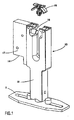
- FIG. 1 is an exploded perspective view of a cable mount and fixture having an electrical switch assembly according to the present invention
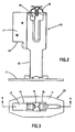
- FIG. 2 is a front view of the cable mount and fixture of FIG. 1, as the cable mount is inserted into the fixture;
- FIG. 3 is a top view of the cable mount and fixture of FIG. 1, with the cable mount removed;
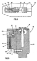
- FIG. 4 is a cross-sectional view taken along lines 4-4 of FIG. 3;
- FIG. 5 is a cross-sectional view taken along lines 5-5 of FIG. 4;
- FIG. 6 is a cross-sectional view similar to FIG. 4, after the cable mount is inserted into the fixture;
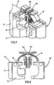
- FIG. 7 is an enlarged perspective view of a cable mount according to another embodiment of the present invention.
- FIG. 8 is an enlarged front view of the cable mount of FIG. 7, as the cable mount is inserted into the fixture.
- the illustrated embodiments of the invention are directed to a cable mount and fixture having an electrical switch assembly that provides electrical verification that a cable mount is correctly installed in the fixture.
- FIG. 1 shows a cable mount and fixture having electrical switch assembly 10.
- assembly 10 includes base 11 mountable to a harness board (not shown) utilizing fasteners or other securement devices.
- Mounting fixture 12 such as the one disclosed in U.S. Patent No. 5,799,906, mounts to base 11.
- Assembly 10 also includes a switch assembly 14 secured to mounting fixture 12 utilizing a fastener or other securement device.
- Switch assembly 14 includes an actuating signal that informs a user when cable mount 16, such as the one disclosed in U.S. Patent No. 5,368,261, is correctly installed into mounting fixture 12.
- the disclosures of U.S. Patent Nos. 5,799,906 and 5,368,261 are incorporated by reference.
- switch assembly 14 has a housing 17, a contact pin 18, a right angle arm 22 having pivot point 24 and contacts 26, 28.
- Contact pin 18 slip fits into a side of mounting fixture 12, and extends into an opening defined within mounting fixture 12.
- Contact pin 18 includes insulating washer 20, which provides electrical insulation between contact pin 18 and right angle arm 22.
- Right angle arm 22 is connected to housing 17 at pivot point 24, and right angle arm 22 is in contact with contact pin 18.
- the electrical circuit comprising right angle arm 22 and contacts 26, 28 is open.
- Contacts 26, 28 include sleeves 27, 29 respectively, which support spring pins (not shown) positioned therein.
- mounting fixture 12 contact pin 18, right angle arm 22 and contacts 26, 28 are metal.
- housing 17 and insulating washer 20 are plastic.
- right angle arm 22 may be plastic. In such a design, a metal plate would be inserted on plastic right angle arm 22 to allow current to flow between contacts 26, 28.
- FIGS. 7 and 8 show an alternate embodiment of cable mount 16.
- the cable mount disclosed In FIGS. 7 and 8 is similar to the cable mount disclosed in U.S. Patent No. 5,368,261, except that the cable mount saddle support has two retention tabs 30, 32 to improve friction between cable mount 16 and the wires. The additional friction provided by retention tabs 30, 32 minimizes slippage of wires across the top of cable mount 16.
- the disclosed invention provides a cable mount and fixture having an electrical switch assembly that provides user feedback when the cable mount is properly installed in the fixture. It should be noted that the above-described and illustrated embodiments and preferred embodiments of the invention are not an exhaustive listing of the forms such an assembly in accordance with the invention might take; rather, they serve as exemplary and illustrative of embodiments of the invention as presently understood. Many other forms of the invention are believed to exist.
Landscapes
- Installation Of Indoor Wiring (AREA)
Applications Claiming Priority (4)
| Application Number | Priority Date | Filing Date | Title |
|---|---|---|---|
| US49914803P | 2003-08-29 | 2003-08-29 | |
| US499148P | 2003-08-29 | ||
| US927304P | 2004-08-26 | ||
| US10/927,304 US7278614B2 (en) | 2003-08-29 | 2004-08-26 | Cable mount and fixture having electrical switch assembly |
Publications (2)
| Publication Number | Publication Date |
|---|---|
| EP1510295A2 true EP1510295A2 (fr) | 2005-03-02 |
| EP1510295A3 EP1510295A3 (fr) | 2009-05-20 |
Family
ID=34381030
Family Applications (1)
| Application Number | Title | Priority Date | Filing Date |
|---|---|---|---|
| EP04255191A Withdrawn EP1510295A3 (fr) | 2003-08-29 | 2004-08-27 | Dispositif pour supporter et fixer un câble avec unité à commutateur électrique |
Country Status (4)
| Country | Link |
|---|---|
| US (1) | US7278614B2 (fr) |
| EP (1) | EP1510295A3 (fr) |
| JP (1) | JP2005076888A (fr) |
| MX (1) | MXPA04008368A (fr) |
Cited By (1)
| Publication number | Priority date | Publication date | Assignee | Title |
|---|---|---|---|---|
| US11708918B1 (en) * | 2022-03-22 | 2023-07-25 | Concealfab, Inc. | Grip enhancing low-PIM cable tie anchor |
Families Citing this family (2)
| Publication number | Priority date | Publication date | Assignee | Title |
|---|---|---|---|---|
| US10256011B2 (en) | 2014-10-31 | 2019-04-09 | Panduit Corp. | Wire harness assembly system |
| US10253914B2 (en) * | 2016-07-21 | 2019-04-09 | Ford Global Technologies, Llc | Clip having positive installation indicator for securing fuel line to foam part |
Citations (1)
| Publication number | Priority date | Publication date | Assignee | Title |
|---|---|---|---|---|
| US5368261A (en) | 1992-12-17 | 1994-11-29 | Panduit Corp. | Cable mount and fixture |
Family Cites Families (13)
| Publication number | Priority date | Publication date | Assignee | Title |
|---|---|---|---|---|
| US4042123A (en) * | 1975-02-06 | 1977-08-16 | Sheldon Loren B | Automated pipe handling system |
| US4073200A (en) * | 1976-08-09 | 1978-02-14 | Allis-Chalmers Corporation | Cable retainer |
| US4462523A (en) * | 1982-09-29 | 1984-07-31 | Material Control, Inc. | Damaged conveyor belt detector |
| US4609910A (en) * | 1985-04-09 | 1986-09-02 | Geringer Arthur V | Exit door security system |
| US4992777A (en) * | 1987-08-10 | 1991-02-12 | Omron Tateisi Electronics Co. | Switch device with a trouble detecting and indicating function |
| US5243325A (en) * | 1991-12-23 | 1993-09-07 | Marin Ricardo E | Latch gate alarm switch assembly |
| US5654788A (en) * | 1995-02-10 | 1997-08-05 | Eastman Kodak Company | Cartridge sensing device |
| US5714940A (en) * | 1996-09-26 | 1998-02-03 | Eaton Corporation | Bell alarm for system power breaker |
| US6043433A (en) * | 1998-02-20 | 2000-03-28 | E.O. Schweitzer Manufacturing Co., Inc. | Cable clamp with universal positioning |
| US6732893B2 (en) * | 1998-12-09 | 2004-05-11 | Danik Industries, Ltd. | Self-locking bicycle carrier |
| US6283349B1 (en) * | 1998-12-09 | 2001-09-04 | Danik Industries Ltd. | Self-locking bicycle carrier |
| JP2001268753A (ja) * | 2000-03-17 | 2001-09-28 | Sumitomo Wiring Syst Ltd | ワイヤハーネス保持部材の検知装置 |
| US6910840B2 (en) * | 2003-06-06 | 2005-06-28 | National Molding Corp. | Fastener |
-
2004
- 2004-08-26 US US10/927,304 patent/US7278614B2/en not_active Expired - Fee Related
- 2004-08-27 MX MXPA04008368A patent/MXPA04008368A/es active IP Right Grant
- 2004-08-27 EP EP04255191A patent/EP1510295A3/fr not_active Withdrawn
- 2004-08-27 JP JP2004248575A patent/JP2005076888A/ja active Pending
Patent Citations (2)
| Publication number | Priority date | Publication date | Assignee | Title |
|---|---|---|---|---|
| US5368261A (en) | 1992-12-17 | 1994-11-29 | Panduit Corp. | Cable mount and fixture |
| US5799906A (en) | 1992-12-17 | 1998-09-01 | Hillegonds; Larry A. | Cable mount and fixture |
Cited By (1)
| Publication number | Priority date | Publication date | Assignee | Title |
|---|---|---|---|---|
| US11708918B1 (en) * | 2022-03-22 | 2023-07-25 | Concealfab, Inc. | Grip enhancing low-PIM cable tie anchor |
Also Published As
| Publication number | Publication date |
|---|---|
| EP1510295A3 (fr) | 2009-05-20 |
| MXPA04008368A (es) | 2008-10-02 |
| JP2005076888A (ja) | 2005-03-24 |
| US20050067537A1 (en) | 2005-03-31 |
| US7278614B2 (en) | 2007-10-09 |
Similar Documents
| Publication | Publication Date | Title |
|---|---|---|
| US7210957B2 (en) | Flexible high-power LED lighting system | |
| US7597594B2 (en) | Electrical connecting terminal | |
| CN105531879B (zh) | 适用于印刷电路板的电连接器 | |
| US9239136B1 (en) | Connector for light-emitting diode strip | |
| US7048591B1 (en) | Terminal-mounting seat | |
| US5684676A (en) | Clip for securing heat dissipator to computer central processing unit | |
| CN109681821B (zh) | 吸顶灯及其灯体、安装座 | |
| TWM301438U (en) | Connector and guide placement member | |
| US20030031004A1 (en) | Screwless circuit board attachment | |
| JP5212633B2 (ja) | 端子台および照明器具 | |
| US6851964B2 (en) | Retainer clip for ribbon cable connectors | |
| EP1440857B1 (fr) | Dispositif de fixage d'un tige d'actionnement d'un servofrein à un pédale de frein | |
| US7436671B2 (en) | Retention module for a heat sink | |
| US4917624A (en) | Socket for printed circuit board | |
| US7278614B2 (en) | Cable mount and fixture having electrical switch assembly | |
| US8247719B2 (en) | Button device | |
| US5288249A (en) | Base for cartridge lamp | |
| JP6342475B2 (ja) | 取り付けやすい照明器具 | |
| JP2018137181A (ja) | 光源ユニット、及び照明器具 | |
| CN110906218B (zh) | 一种吸顶灯 | |
| JP2003331635A (ja) | 発光ダイオードの固定構造 | |
| JP2017134916A (ja) | 照明器具 | |
| JP3409233B2 (ja) | 電線接続構造 | |
| JPH11214103A (ja) | ランプソケット | |
| KR100222249B1 (ko) | 와이어 고정용 클립 |
Legal Events
| Date | Code | Title | Description |
|---|---|---|---|
| PUAI | Public reference made under article 153(3) epc to a published international application that has entered the european phase |
Free format text: ORIGINAL CODE: 0009012 |
|
| AK | Designated contracting states |
Kind code of ref document: A2 Designated state(s): AT BE BG CH CY CZ DE DK EE ES FI FR GB GR HU IE IT LI LU MC NL PL PT RO SE SI SK TR |
|
| AX | Request for extension of the european patent |
Extension state: AL HR LT LV MK |
|
| RIN1 | Information on inventor provided before grant (corrected) |
Inventor name: KRONZ, MARTY J. Inventor name: ZERMACH, GARY L. Inventor name: CAVENEY, JACK E. |
|
| PUAL | Search report despatched |
Free format text: ORIGINAL CODE: 0009013 |
|
| AK | Designated contracting states |
Kind code of ref document: A3 Designated state(s): AT BE BG CH CY CZ DE DK EE ES FI FR GB GR HU IE IT LI LU MC NL PL PT RO SE SI SK TR |
|
| AX | Request for extension of the european patent |
Extension state: AL HR LT LV MK |
|
| 17P | Request for examination filed |
Effective date: 20090723 |
|
| STAA | Information on the status of an ep patent application or granted ep patent |
Free format text: STATUS: THE APPLICATION HAS BEEN WITHDRAWN |
|
| 18W | Application withdrawn |
Effective date: 20090907 |