EP1510376A2 - Klimaanlage, insbesondere für Fahrzeuge - Google Patents
Klimaanlage, insbesondere für Fahrzeuge Download PDFInfo
- Publication number
- EP1510376A2 EP1510376A2 EP03292116A EP03292116A EP1510376A2 EP 1510376 A2 EP1510376 A2 EP 1510376A2 EP 03292116 A EP03292116 A EP 03292116A EP 03292116 A EP03292116 A EP 03292116A EP 1510376 A2 EP1510376 A2 EP 1510376A2
- Authority
- EP
- European Patent Office
- Prior art keywords
- air
- bypass
- heat exchanger
- conditioning system
- air conditioning
- Prior art date
- Legal status (The legal status is an assumption and is not a legal conclusion. Google has not performed a legal analysis and makes no representation as to the accuracy of the status listed.)
- Granted
Links
Images

Classifications
-
- B—PERFORMING OPERATIONS; TRANSPORTING
- B60—VEHICLES IN GENERAL
- B60H—ARRANGEMENTS OF HEATING, COOLING, VENTILATING OR OTHER AIR-TREATING DEVICES SPECIALLY ADAPTED FOR PASSENGER OR GOODS SPACES OF VEHICLES
- B60H1/00—Heating, cooling or ventilating devices
- B60H1/00007—Combined heating, ventilating, or cooling devices
- B60H1/00021—Air flow details of HVAC devices
- B60H1/00035—Air flow details of HVAC devices for sending an air stream of uniform temperature into the passenger compartment
- B60H1/0005—Air flow details of HVAC devices for sending an air stream of uniform temperature into the passenger compartment the air being firstly cooled and subsequently heated or vice versa
-
- B—PERFORMING OPERATIONS; TRANSPORTING
- B60—VEHICLES IN GENERAL
- B60H—ARRANGEMENTS OF HEATING, COOLING, VENTILATING OR OTHER AIR-TREATING DEVICES SPECIALLY ADAPTED FOR PASSENGER OR GOODS SPACES OF VEHICLES
- B60H1/00—Heating, cooling or ventilating devices
- B60H1/00007—Combined heating, ventilating, or cooling devices
- B60H1/00021—Air flow details of HVAC devices
- B60H2001/00114—Heating or cooling details
- B60H2001/00135—Deviding walls for separate air flows
Definitions
- the invention relates to an air conditioner, in particular for vehicles, with a Air conveyor and an evaporator.
- the invention has for its object to provide an air conditioning, the has an optimally small space, has only a small pressure loss and works very quietly.
- this object is achieved in that the particular designed as an evaporator heat exchanger a separator for Distribution of the heat exchanger flowing through, from the air conveyor subsidized air flow is associated with partial air flows.
- this separating element which is preferably designed as a partition, is from the outset the symmetry or asymmetry ratios Taken into account, so that in the places where the Air exits the desired mass flows and set temperatures.
- the air conditioner in a rear of a vehicle, so is arranged by means of the corresponding Separating element, a division of the air flow in partial air streams possible, such that, for example, at the B-pillars (B1, B2) and C-pillars (C1 and C2) the mass flows emerge symmetrically and, if desired, in each case air with the same temperature flows out.
- the separating element of the heat exchanger preferably asymmetrically divided into two corresponding zones.
- the asymmetry takes into account the different channel lengths to the B and / or C-pillars, so that sets a compensation and extent the air conditioning conditions inside the vehicle cab again symmetrical are.
- the invention is of course not on an additional air conditioning or a rear air conditioning limited.
- At least one bypass for introducing of bypass air in at least one of the coming from the heat exchanger Partial air flows provided.
- the bypass air happens the heat exchanger is not and is therefore different than the associated Partial air flow - not thermally influenced.
- each partial air flow is bypassed for the Initiation of bypass air is assigned, that is, in the already mentioned two-tone design, two bypasses are provided and the heat exchanger is divided by the separating element into two zones, wherein the a zone with associated bypass the left side of the motor vehicle and the other zone with associated bypass the right side of the motor vehicle provided.
- each bypass has a bypass mixing valve.
- the air conveyor a Suction is, seen in the flow direction- the heat exchanger is downstream and thus the air through the heat exchanger sucks and also encourages the air sucking through the bypasses.
- the air conveyor is designed two-tone, that is each partial air flow with associated bypass air flow is separated from a Suction zone of the air conveyor. This can be done, for example take place that the air conveyor several, not ventilation technology with each other having communicating wheels.
- At least one Bypass air flow channel-like on the heat exchanger or a part of this is passed.
- this is not done laterally, but preferably under or above the heat exchanger, so that the side dimension the air conditioning is not increased.
- the channel-like line realized by the bypass air flow by means of a tunnel, that is, the associated Bypass air undermines the heat exchanger.
- FIG. 1 shows, in a schematic representation, a plan view of a vehicle 1, which is designed as a passenger car 2.
- the vehicle 1 has an engine compartment 3, a passenger compartment 4 and a trunk 5.
- Im Engine compartment 3 is an unillustrated drive motor and a Front air conditioner 6, which forms a main air conditioner 7 of the vehicle 1. It supplies a left-side air outlet A, a right-side air outlet A1 as well as a central air outlet A2.
- the air outlets A, A1 and A2 are housed in the area of the dashboard of the vehicle 1.
- the backrests of the front seats 8 of the vehicle 1 is on the right Side the so-called B1-pillar and on the left side the so-called B2-pillar the body arranged.
- the rear area of the vehicle 1 is located on the right side of the C1 column and on the left side the C2 column. According to the names of the mentioned columns There are air outlets on these, that is, there is a right-sided Air outlet B1, a left-side air outlet B2 and a right-sided Air outlet C1 and finally a left-side air outlet C2.
- the air outlets B1, B2, C1 and C2 belong to an auxiliary air conditioning system 9, the -im Contrary to the main air conditioning system 7 referred to as a rear air conditioner 10 becomes.
- a rear air conditioner 10 As can be seen in FIG. 1, it is under the right front seat 8 arranged and supplies-as the name says- the rear area of the vehicle 1.
- suitable air ducts 11 and blower 12 supplies the auxiliary air conditioning 9 the air outlets B1, B2, C1 and C2.
- FIG. 2 shows, schematically, an evaporator 13 formed heat exchanger 14 of the auxiliary air conditioning system 9. It can be seen that by means of an air conveyor, not shown, air (arrow 15) is promoted, which passes the evaporator 13.
- the evaporator 13 is -in Seen flow direction- a separating element 16 downstream or upstream, which divides the air (arrow 15) into partial air streams 17, 18, the division due to an asymmetrical arrangement to the longitudinal central axis of the evaporator 13 is different in size, that is, the mass flow of the partial air flow 17 is greater than that of the partial air flow 18. Accordingly, the distance of the separating element 16 from the associated side edge of the evaporator 13 in the case of the partial air flow 17, the dimension X and in the case of the partial air flow 18 is the measure Y, where X ⁇ Y.
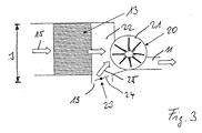
- FIG. 3 illustrates - also in a schematic representation - at some the components of the auxiliary air conditioning system 9, that the evaporator 13 a bypass 19 is assigned.
- Downstream of the evaporator 13 is the air conveyor 20, which accordingly formed as a suction device 21 is. Due to the suction effect of the air conveyor 20 air is according to Arrow 15 sucked, which passes through the evaporator 13 and cools there. The air enters a mixing chamber 22, in which the bypass 19 opens.
- the Bypass 19 has a bypass mixing valve 23 in the form of a mixing flap 24th on, by means of a control or regulating device, not shown the additional air conditioner 9 in a corresponding rotational position is adjusted, so that -these Dreh ein- a assigned bypass air flow 25 sets.
- the mixing chamber 22 meets the air coming from the evaporator 13 to the air of the bypass air flow 25th and mixes there. Together, the mixed air is promoted by the Suction of the air conveyor 20- introduced into the air duct 11 and directed from there to the corresponding air outlets of the vehicle 1.
- the separating element 16 is of simplicity half-not shown. It should only be clarified that the of Evaporator 13 incoming air flow with the bypass air flow 25 a Angle includes, in the embodiment shown, 90 ° or is about 90 °. Consequently, the bypass air flows laterally into the air, which comes from the evaporator 13. In this coming from the evaporator 13 Air may in particular be partial air flows 17 or 18 act (see Figure 2). Because of this lateral airflow leaves realize a very narrow design, which in the figure 13 schematically marked with the dimension s.
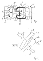
- FIG. 4 illustrates, in a more concrete illustration, the structure of the rear air conditioning system
- the invention does not refer to such Air conditioning is limited, but for example, in front air conditioning systems or in general terms for air conditioning systems can.
- a lower part 26 of a housing 27 of the additional air conditioning 9. It carries in its interior 28 as a heat exchanger 14th trained evaporator 13 and a lower part 29 of the otherwise not closer Furthermore, a bypass 19 and a Bypass 30 recognizable.
- the bypasses 19, 30 each have bypass mixing valves 23, 31, the two actuators 32, 33 in the operating mode appropriate positions are brought.
- the two bypass mixing valves 23 and 31 are formed as mixing flaps 24 and 34.
- the evaporator 13 is arranged in the interior 28 of the housing 27 of the auxiliary air conditioning system 9, that it has a distance t to the inside 35 of the housing 27. This Distance t is realized by means of spacers 36.
- Dividing element 16 designed as a dividing wall 38 divides the evaporator 13 in a zone X and a zone Y, wherein -as above already set out - an asymmetric division is realized.
- the zone X extends below the evaporator 13 of the bypass 19 in Shape of a triangular channel 39, that is, this channel 39 forms a Tunnel 40, which leads to the zone Y of the heat exchanger 14.
- the cross section of the tunnel 40 is triangular and also the Shape of the partition 38 designed substantially triangular.
- Zone X results in air being sucked in and out of air inlet 37 the effect of the partition wall 38 as a partial air flow 17 under the evaporator thirteenth reaches in the area of zone X and there - ascending upward - the heat exchanger 14 in the area of zone X interspersed.
- On the now cooled Air meets-over the bypass 30- a bypass airflow 41.
- the size of this Bypass air flow 41 is determined by the opening angle of the mixing flap 34.
- the mixed air then passes to the suction effect unfolding, assigned Impeller of the air conveyor 20 and from there into the air ducts 11 to the associated air outlets B1 and C1.
- the following air flow sets in: Due to the suction effect of this zone Y associated impeller of the air conveyor 20 air is sucked through the air inlet 37 which sweeps as a partial air stream 18 from above the zone Y of the evaporator 13 and then passes down through the heat exchanger 14. In accordance with the opened mixing flap 24 of the bypass 19, a bypass air flow 25 enters the bypass 19 and underflows due to the formation of the tunnel 40, the zone X of the evaporator 13. The bypass air flow 25 occurs below the zone Y of the evaporator 13 and meets there on the partial air flow 18, which has passed through the heat exchanger 14 in the zone Y.
Landscapes
- Physics & Mathematics (AREA)
- Thermal Sciences (AREA)
- Engineering & Computer Science (AREA)
- Mechanical Engineering (AREA)
- Air-Conditioning For Vehicles (AREA)
Abstract
Description
- Figur 1
- eine schematische Draufsicht auf ein mit Klimaanlage ausgestattetes Fahrzeug,
- Figur 2
- eine schematische Ansicht der Luftaufteilung an einem Wärmetauscher, insbesondere Verdampfer, der Klimaanlage,
- Figur 3
- ein Prinzipbild der Luftführung der Klimaanlage und
- Figur 4
- eine Klimaanlage mit geöffnetem Gehäuse, wobei die obere Gehäusehälfte mit entsprechenden Einbauten nicht wiedergegeben ist.
Der Figur 4 ist deutlich entnehmbar, dass der jeweilige Teilluftstrom unter einem Winkel von etwa 90° auf den zugeordneten Bypassluftstrom trifft.
Claims (12)
- Klimaanlage, insbesondere für Fahrzeuge, mit einer Luftfördereinrichtung und einem, insbesondere als Verdampfer ausgebildeten Wärmetauscher, dadurch gekennzeichnet, dass dem Wärmetauscher (14) ein Trennelement (16) zur Aufteilung des den Wärmetauscher (14) durchströmenden, von der Luftfördereinrichtung (20) geförderten Luftstroms in Teilluftströme (17,18) zugeordnet ist.
- Klimaanlage nach Anspruch 1, dadurch gekennzeichnet, dass das Trennelement (16) den Wärmetauscher (14) derart zonal aufteilt, dass die Massenströme und/oder die Lufttemperaturen sich in gewünschter Weise in den Teilluftströmen (17,18) einstellen.
- Klimaanlage nach einem der vorhergehenden Ansprüche, dadurch gekennzeichnet, dass das Trennelement (16) den Wärmetauscher (14) asymmetrisch aufteilt.
- Klimaanlage nach einem der vorhergehenden Ansprüche, dadurch gekennzeichnet, dass mindestens ein Bypass (19,30) zum Einleiten von Bypassluft (Bypassluftströme 25, 41) in mindestens einen der vom Wärmetauscher (14) kommenden Teilluftströme (17,18) vorgesehen ist.
- Klimaanlage nach einem der vorhergehenden Ansprüche, dadurch gekennzeichnet, dass jedem Teilluftstrom (17,18) ein Bypass (19,30) für das jeweilige Einleiten von Bypassluft zugeordnet ist.
- Klimaanlage nach einem der vorhergehenden Ansprüche, dadurch gekennzeichnet, dass jeder Bypass (19,30) ein Bypassmischventil (23,31) aufweist.
- Klimaanlage nach einem der vorhergehenden Ansprüche, dadurch gekennzeichnet, dass mindestens einem der vom Wärmetauscher (14) kommenden Teilluftströme (17,18) der zugeordnete Bypassluftstrom (25,41) unter einem Winkel seitlich zugeführt wird.
- Klimaanlage nach einem der vorhergehenden Ansprüche, dadurch gekennzeichnet, dass die Luftfördereinrichtung (20) als Saugeinrichtung (21) ausgebildet ist.
- Klimaanlage nach einem der vorhergehenden Ansprüche, dadurch gekennzeichnet, dass mindestens ein Bypassluftstrom (25,41) kanalartig am Wärmetauscher (14) oder einem Teil von diesem vorbeigeführt wird.
- Klimaanlage nach einem der vorhergehenden Ansprüche, dadurch gekennzeichnet, dass die kanalartige Leitung des Bypassluftstroms (25,41) mittels eines den Wärmetauscher zumindest bereichsweise passierenden Tunnels (40) erfolgt.
- Klimaanlage nach einem der vorhergehenden Ansprüche, gekennzeichnet durch die Ausbildung als Zusatzklimaanlage (9).
- Klimaanlage nach einem der vorhergehenden Ansprüche, gekennzeichnet durch die Ausbildung als Heck-Klimaanlage (10).
Priority Applications (3)
| Application Number | Priority Date | Filing Date | Title |
|---|---|---|---|
| AT03292116T ATE430047T1 (de) | 2003-08-27 | 2003-08-27 | Klimaanlage, insbesondere für fahrzeuge |
| DE50311480T DE50311480D1 (de) | 2003-08-27 | 2003-08-27 | Klimaanlage, insbesondere für Fahrzeuge |
| EP03292116A EP1510376B1 (de) | 2003-08-27 | 2003-08-27 | Klimaanlage, insbesondere für Fahrzeuge |
Applications Claiming Priority (1)
| Application Number | Priority Date | Filing Date | Title |
|---|---|---|---|
| EP03292116A EP1510376B1 (de) | 2003-08-27 | 2003-08-27 | Klimaanlage, insbesondere für Fahrzeuge |
Publications (3)
| Publication Number | Publication Date |
|---|---|
| EP1510376A2 true EP1510376A2 (de) | 2005-03-02 |
| EP1510376A3 EP1510376A3 (de) | 2005-04-27 |
| EP1510376B1 EP1510376B1 (de) | 2009-04-29 |
Family
ID=34089758
Family Applications (1)
| Application Number | Title | Priority Date | Filing Date |
|---|---|---|---|
| EP03292116A Expired - Lifetime EP1510376B1 (de) | 2003-08-27 | 2003-08-27 | Klimaanlage, insbesondere für Fahrzeuge |
Country Status (3)
| Country | Link |
|---|---|
| EP (1) | EP1510376B1 (de) |
| AT (1) | ATE430047T1 (de) |
| DE (1) | DE50311480D1 (de) |
Families Citing this family (1)
| Publication number | Priority date | Publication date | Assignee | Title |
|---|---|---|---|---|
| US20240367478A1 (en) * | 2021-07-22 | 2024-11-07 | Gentherm Gmbh | Dual-flow climatization system |
Family Cites Families (8)
| Publication number | Priority date | Publication date | Assignee | Title |
|---|---|---|---|---|
| US2647451A (en) * | 1949-07-30 | 1953-08-04 | E A Lab Inc | Automobile heater |
| DE3911494C1 (en) * | 1989-04-08 | 1990-10-04 | Bayerische Motoren Werke Ag, 8000 Muenchen, De | Vehicle heating device with at least two air-inlet flows, the temperatures of which are controlled in different ways |
| JP3321314B2 (ja) * | 1994-09-30 | 2002-09-03 | 株式会社日本クライメイトシステムズ | 車両用後方空気調和装置 |
| JP3692572B2 (ja) * | 1995-10-12 | 2005-09-07 | 株式会社デンソー | 空調装置 |
| FR2754491B1 (fr) * | 1996-10-11 | 1998-12-24 | Valeo Climatisation | Dispositif de chauffage-climatisation de vehicule avec reglage separe des cotes droit et gauche de l'habitacle |
| DE19919132A1 (de) * | 1999-04-27 | 2000-11-02 | Valeo Klimasysteme Gmbh | Temperierung von Belüftungsebenen |
| JP4134479B2 (ja) * | 1999-04-28 | 2008-08-20 | 株式会社デンソー | 車両用空調装置 |
| JP4224939B2 (ja) * | 2000-03-31 | 2009-02-18 | 株式会社デンソー | 車両用空調装置 |
-
2003
- 2003-08-27 EP EP03292116A patent/EP1510376B1/de not_active Expired - Lifetime
- 2003-08-27 AT AT03292116T patent/ATE430047T1/de not_active IP Right Cessation
- 2003-08-27 DE DE50311480T patent/DE50311480D1/de not_active Expired - Lifetime
Also Published As
| Publication number | Publication date |
|---|---|
| EP1510376A3 (de) | 2005-04-27 |
| ATE430047T1 (de) | 2009-05-15 |
| EP1510376B1 (de) | 2009-04-29 |
| DE50311480D1 (de) | 2009-06-10 |
Similar Documents
| Publication | Publication Date | Title |
|---|---|---|
| EP0841201B2 (de) | Heiz- oder Klimaanlage für ein Kraftfahrzeug | |
| DE102004027689A1 (de) | Klimaanlage für ein Kraftfahrzeug | |
| DE10057039A1 (de) | Heizungs- oder Klimaanlage für ein Kraftfahrzeug | |
| DE102009044760B4 (de) | Klimaanlage für ein Kraftfahrzeug | |
| DE19804287C5 (de) | Klimaanlage für Fahrzeuge | |
| EP2015948B1 (de) | Kraftfahrzeug-klimaanlage | |
| DE3925726C2 (de) | ||
| EP1641642B1 (de) | Kraftfahrzeug-klimaanlage | |
| EP2011675B1 (de) | Klimaanlage | |
| EP2048010B1 (de) | Kraftfahrzeug-Klimaanlagenanordnung | |
| DE102007013432A1 (de) | Warmluftkanal für ein Klimagerät eines Kraftfahrzeuges | |
| EP1510375B1 (de) | Klimaanlage sowie Verfahren zum Betreiben einer solchen | |
| EP1510376A2 (de) | Klimaanlage, insbesondere für Fahrzeuge | |
| DE10353191A1 (de) | Kraftfahrzeug-Klimananlage | |
| DE102019206851A1 (de) | Klimatisierungseinrichtung für ein Kraftfahrzeug, Kraftfahrzeug | |
| EP2011676B1 (de) | Klimaanlage | |
| DE102004030672B4 (de) | V-förmige Wärmetauscheranordnung einer Heiz-Klimaanlage | |
| DE102018121512B4 (de) | Klimagerät für ein Kraftfahrzeug | |
| EP1674308B1 (de) | Klimaanlage, insbesondere Zusatzklimaanlage mit elektrischem Zuheizer | |
| DE10320750A1 (de) | Klimaanlage | |
| EP1741581B1 (de) | Fondbelüftungs-, Heizungs- oder Klimaanlage | |
| DE102007025371B4 (de) | Klimatisierungsgerät, insbesondere für Kraftfahrzeuge | |
| DE102006012400B4 (de) | Heiz- und Lüftungsanlage für ein Fahrzeug mit einem der Mischklappe nachgeschaltetenKaltluftbypass | |
| EP1972473B1 (de) | Klimaanlage für ein Kraftfahrzeug | |
| EP1641641B1 (de) | Belüftungsvorrichtung, insbesondere für eine heizung oder klimaanlage eines kraftfahrzeugs |
Legal Events
| Date | Code | Title | Description |
|---|---|---|---|
| PUAI | Public reference made under article 153(3) epc to a published international application that has entered the european phase |
Free format text: ORIGINAL CODE: 0009012 |
|
| AK | Designated contracting states |
Kind code of ref document: A2 Designated state(s): AT BE BG CH CY CZ DE DK EE ES FI FR GB GR HU IE IT LI LU MC NL PT RO SE SI SK TR |
|
| AX | Request for extension of the european patent |
Extension state: AL LT LV MK |
|
| PUAL | Search report despatched |
Free format text: ORIGINAL CODE: 0009013 |
|
| AK | Designated contracting states |
Kind code of ref document: A3 Designated state(s): AT BE BG CH CY CZ DE DK EE ES FI FR GB GR HU IE IT LI LU MC NL PT RO SE SI SK TR |
|
| AX | Request for extension of the european patent |
Extension state: AL LT LV MK |
|
| RAP1 | Party data changed (applicant data changed or rights of an application transferred) |
Owner name: BEHR FRANCE ROUFFACH SAS |
|
| 17P | Request for examination filed |
Effective date: 20051027 |
|
| AKX | Designation fees paid |
Designated state(s): AT BE BG CH CY CZ DE DK EE ES FI FR GB GR HU IE IT LI LU MC NL PT RO SE SI SK TR |
|
| 17Q | First examination report despatched |
Effective date: 20060424 |
|
| GRAP | Despatch of communication of intention to grant a patent |
Free format text: ORIGINAL CODE: EPIDOSNIGR1 |
|
| GRAS | Grant fee paid |
Free format text: ORIGINAL CODE: EPIDOSNIGR3 |
|
| GRAA | (expected) grant |
Free format text: ORIGINAL CODE: 0009210 |
|
| AK | Designated contracting states |
Kind code of ref document: B1 Designated state(s): AT BE BG CH CY CZ DE DK EE ES FI FR GB GR HU IE IT LI LU MC NL PT RO SE SI SK TR |
|
| REG | Reference to a national code |
Ref country code: GB Ref legal event code: FG4D Free format text: NOT ENGLISH |
|
| REG | Reference to a national code |
Ref country code: CH Ref legal event code: EP |
|
| REF | Corresponds to: |
Ref document number: 50311480 Country of ref document: DE Date of ref document: 20090610 Kind code of ref document: P |
|
| REG | Reference to a national code |
Ref country code: IE Ref legal event code: FG4D |
|
| NLV1 | Nl: lapsed or annulled due to failure to fulfill the requirements of art. 29p and 29m of the patents act | ||
| PG25 | Lapsed in a contracting state [announced via postgrant information from national office to epo] |
Ref country code: FI Free format text: LAPSE BECAUSE OF FAILURE TO SUBMIT A TRANSLATION OF THE DESCRIPTION OR TO PAY THE FEE WITHIN THE PRESCRIBED TIME-LIMIT Effective date: 20090429 Ref country code: PT Free format text: LAPSE BECAUSE OF FAILURE TO SUBMIT A TRANSLATION OF THE DESCRIPTION OR TO PAY THE FEE WITHIN THE PRESCRIBED TIME-LIMIT Effective date: 20090829 Ref country code: ES Free format text: LAPSE BECAUSE OF FAILURE TO SUBMIT A TRANSLATION OF THE DESCRIPTION OR TO PAY THE FEE WITHIN THE PRESCRIBED TIME-LIMIT Effective date: 20090809 |
|
| PG25 | Lapsed in a contracting state [announced via postgrant information from national office to epo] |
Ref country code: NL Free format text: LAPSE BECAUSE OF FAILURE TO SUBMIT A TRANSLATION OF THE DESCRIPTION OR TO PAY THE FEE WITHIN THE PRESCRIBED TIME-LIMIT Effective date: 20090429 Ref country code: SE Free format text: LAPSE BECAUSE OF FAILURE TO SUBMIT A TRANSLATION OF THE DESCRIPTION OR TO PAY THE FEE WITHIN THE PRESCRIBED TIME-LIMIT Effective date: 20090729 Ref country code: SI Free format text: LAPSE BECAUSE OF FAILURE TO SUBMIT A TRANSLATION OF THE DESCRIPTION OR TO PAY THE FEE WITHIN THE PRESCRIBED TIME-LIMIT Effective date: 20090429 |
|
| REG | Reference to a national code |
Ref country code: IE Ref legal event code: FD4D |
|
| PG25 | Lapsed in a contracting state [announced via postgrant information from national office to epo] |
Ref country code: CZ Free format text: LAPSE BECAUSE OF FAILURE TO SUBMIT A TRANSLATION OF THE DESCRIPTION OR TO PAY THE FEE WITHIN THE PRESCRIBED TIME-LIMIT Effective date: 20090429 Ref country code: IE Free format text: LAPSE BECAUSE OF FAILURE TO SUBMIT A TRANSLATION OF THE DESCRIPTION OR TO PAY THE FEE WITHIN THE PRESCRIBED TIME-LIMIT Effective date: 20090429 Ref country code: EE Free format text: LAPSE BECAUSE OF FAILURE TO SUBMIT A TRANSLATION OF THE DESCRIPTION OR TO PAY THE FEE WITHIN THE PRESCRIBED TIME-LIMIT Effective date: 20090429 Ref country code: DK Free format text: LAPSE BECAUSE OF FAILURE TO SUBMIT A TRANSLATION OF THE DESCRIPTION OR TO PAY THE FEE WITHIN THE PRESCRIBED TIME-LIMIT Effective date: 20090429 Ref country code: RO Free format text: LAPSE BECAUSE OF FAILURE TO SUBMIT A TRANSLATION OF THE DESCRIPTION OR TO PAY THE FEE WITHIN THE PRESCRIBED TIME-LIMIT Effective date: 20090429 |
|
| PG25 | Lapsed in a contracting state [announced via postgrant information from national office to epo] |
Ref country code: SK Free format text: LAPSE BECAUSE OF FAILURE TO SUBMIT A TRANSLATION OF THE DESCRIPTION OR TO PAY THE FEE WITHIN THE PRESCRIBED TIME-LIMIT Effective date: 20090429 |
|
| BERE | Be: lapsed |
Owner name: BEHR FRANCE ROUFFACH SAS Effective date: 20090831 |
|
| PLBE | No opposition filed within time limit |
Free format text: ORIGINAL CODE: 0009261 |
|
| STAA | Information on the status of an ep patent application or granted ep patent |
Free format text: STATUS: NO OPPOSITION FILED WITHIN TIME LIMIT |
|
| PG25 | Lapsed in a contracting state [announced via postgrant information from national office to epo] |
Ref country code: BG Free format text: LAPSE BECAUSE OF FAILURE TO SUBMIT A TRANSLATION OF THE DESCRIPTION OR TO PAY THE FEE WITHIN THE PRESCRIBED TIME-LIMIT Effective date: 20090729 Ref country code: MC Free format text: LAPSE BECAUSE OF NON-PAYMENT OF DUE FEES Effective date: 20090831 |
|
| REG | Reference to a national code |
Ref country code: CH Ref legal event code: PL |
|
| 26N | No opposition filed |
Effective date: 20100201 |
|
| GBPC | Gb: european patent ceased through non-payment of renewal fee |
Effective date: 20090827 |
|
| PG25 | Lapsed in a contracting state [announced via postgrant information from national office to epo] |
Ref country code: LI Free format text: LAPSE BECAUSE OF NON-PAYMENT OF DUE FEES Effective date: 20090831 Ref country code: CH Free format text: LAPSE BECAUSE OF NON-PAYMENT OF DUE FEES Effective date: 20090831 |
|
| PG25 | Lapsed in a contracting state [announced via postgrant information from national office to epo] |
Ref country code: BE Free format text: LAPSE BECAUSE OF NON-PAYMENT OF DUE FEES Effective date: 20090831 |
|
| PG25 | Lapsed in a contracting state [announced via postgrant information from national office to epo] |
Ref country code: GR Free format text: LAPSE BECAUSE OF FAILURE TO SUBMIT A TRANSLATION OF THE DESCRIPTION OR TO PAY THE FEE WITHIN THE PRESCRIBED TIME-LIMIT Effective date: 20090730 |
|
| PG25 | Lapsed in a contracting state [announced via postgrant information from national office to epo] |
Ref country code: AT Free format text: LAPSE BECAUSE OF NON-PAYMENT OF DUE FEES Effective date: 20090827 Ref country code: GB Free format text: LAPSE BECAUSE OF NON-PAYMENT OF DUE FEES Effective date: 20090827 |
|
| PG25 | Lapsed in a contracting state [announced via postgrant information from national office to epo] |
Ref country code: IT Free format text: LAPSE BECAUSE OF FAILURE TO SUBMIT A TRANSLATION OF THE DESCRIPTION OR TO PAY THE FEE WITHIN THE PRESCRIBED TIME-LIMIT Effective date: 20090429 |
|
| PG25 | Lapsed in a contracting state [announced via postgrant information from national office to epo] |
Ref country code: LU Free format text: LAPSE BECAUSE OF NON-PAYMENT OF DUE FEES Effective date: 20090827 |
|
| REG | Reference to a national code |
Ref country code: FR Ref legal event code: ST Effective date: 20110502 |
|
| PG25 | Lapsed in a contracting state [announced via postgrant information from national office to epo] |
Ref country code: HU Free format text: LAPSE BECAUSE OF FAILURE TO SUBMIT A TRANSLATION OF THE DESCRIPTION OR TO PAY THE FEE WITHIN THE PRESCRIBED TIME-LIMIT Effective date: 20091030 |
|
| PG25 | Lapsed in a contracting state [announced via postgrant information from national office to epo] |
Ref country code: FR Free format text: LAPSE BECAUSE OF NON-PAYMENT OF DUE FEES Effective date: 20100831 |
|
| PG25 | Lapsed in a contracting state [announced via postgrant information from national office to epo] |
Ref country code: TR Free format text: LAPSE BECAUSE OF FAILURE TO SUBMIT A TRANSLATION OF THE DESCRIPTION OR TO PAY THE FEE WITHIN THE PRESCRIBED TIME-LIMIT Effective date: 20090429 |
|
| PG25 | Lapsed in a contracting state [announced via postgrant information from national office to epo] |
Ref country code: CY Free format text: LAPSE BECAUSE OF FAILURE TO SUBMIT A TRANSLATION OF THE DESCRIPTION OR TO PAY THE FEE WITHIN THE PRESCRIBED TIME-LIMIT Effective date: 20090429 |
|
| PGFP | Annual fee paid to national office [announced via postgrant information from national office to epo] |
Ref country code: FR Payment date: 20090907 Year of fee payment: 7 |
|
| REG | Reference to a national code |
Ref country code: DE Ref legal event code: R082 Ref document number: 50311480 Country of ref document: DE Representative=s name: GRAUEL, ANDREAS, DIPL.-PHYS. DR. RER. NAT., DE Ref country code: DE Ref legal event code: R081 Ref document number: 50311480 Country of ref document: DE Owner name: MAHLE INTERNATIONAL GMBH, DE Free format text: FORMER OWNER: BEHR FRANCE ROUFFACH S.A.S., ROUFFACH, FR |
|
| PGFP | Annual fee paid to national office [announced via postgrant information from national office to epo] |
Ref country code: DE Payment date: 20180831 Year of fee payment: 16 |
|
| REG | Reference to a national code |
Ref country code: DE Ref legal event code: R119 Ref document number: 50311480 Country of ref document: DE |
|
| PG25 | Lapsed in a contracting state [announced via postgrant information from national office to epo] |
Ref country code: DE Free format text: LAPSE BECAUSE OF NON-PAYMENT OF DUE FEES Effective date: 20200303 |