EP1510497A1 - Kran mit einem teleskopierbaren Ausleger, einer Seilwinde und einer Regeleinrichtung - Google Patents
Kran mit einem teleskopierbaren Ausleger, einer Seilwinde und einer Regeleinrichtung Download PDFInfo
- Publication number
- EP1510497A1 EP1510497A1 EP04017614A EP04017614A EP1510497A1 EP 1510497 A1 EP1510497 A1 EP 1510497A1 EP 04017614 A EP04017614 A EP 04017614A EP 04017614 A EP04017614 A EP 04017614A EP 1510497 A1 EP1510497 A1 EP 1510497A1
- Authority
- EP
- European Patent Office
- Prior art keywords
- boom
- deflection roller
- winch
- crane
- telescopic
- Prior art date
- Legal status (The legal status is an assumption and is not a legal conclusion. Google has not performed a legal analysis and makes no representation as to the accuracy of the status listed.)
- Withdrawn
Links
- 238000000034 method Methods 0.000 claims abstract description 10
- 238000005452 bending Methods 0.000 claims description 5
- 230000001939 inductive effect Effects 0.000 claims description 4
- 230000008859 change Effects 0.000 claims description 2
- 230000001105 regulatory effect Effects 0.000 abstract description 3
- 238000001514 detection method Methods 0.000 description 4
- 230000001276 controlling effect Effects 0.000 description 2
- 230000008569 process Effects 0.000 description 2
- 238000010586 diagram Methods 0.000 description 1
- 230000004069 differentiation Effects 0.000 description 1
- 238000012423 maintenance Methods 0.000 description 1
- 230000001360 synchronised effect Effects 0.000 description 1
- 230000007704 transition Effects 0.000 description 1
Images

Classifications
-
- B—PERFORMING OPERATIONS; TRANSPORTING
- B66—HOISTING; LIFTING; HAULING
- B66C—CRANES; LOAD-ENGAGING ELEMENTS OR DEVICES FOR CRANES, CAPSTANS, WINCHES, OR TACKLES
- B66C13/00—Other constructional features or details
- B66C13/18—Control systems or devices
-
- B—PERFORMING OPERATIONS; TRANSPORTING
- B66—HOISTING; LIFTING; HAULING
- B66C—CRANES; LOAD-ENGAGING ELEMENTS OR DEVICES FOR CRANES, CAPSTANS, WINCHES, OR TACKLES
- B66C13/00—Other constructional features or details
- B66C13/18—Control systems or devices
- B66C13/46—Position indicators for suspended loads or for crane elements
-
- B—PERFORMING OPERATIONS; TRANSPORTING
- B66—HOISTING; LIFTING; HAULING
- B66C—CRANES; LOAD-ENGAGING ELEMENTS OR DEVICES FOR CRANES, CAPSTANS, WINCHES, OR TACKLES
- B66C13/00—Other constructional features or details
- B66C13/16—Applications of indicating, registering, or weighing devices
-
- B—PERFORMING OPERATIONS; TRANSPORTING
- B66—HOISTING; LIFTING; HAULING
- B66C—CRANES; LOAD-ENGAGING ELEMENTS OR DEVICES FOR CRANES, CAPSTANS, WINCHES, OR TACKLES
- B66C23/00—Cranes comprising essentially a beam, boom, or triangular structure acting as a cantilever and mounted for translatory of swinging movements in vertical or horizontal planes or a combination of such movements, e.g. jib-cranes, derricks, tower cranes
- B66C23/62—Constructional features or details
- B66C23/64—Jibs
- B66C23/68—Jibs foldable or otherwise adjustable in configuration
-
- B—PERFORMING OPERATIONS; TRANSPORTING
- B66—HOISTING; LIFTING; HAULING
- B66C—CRANES; LOAD-ENGAGING ELEMENTS OR DEVICES FOR CRANES, CAPSTANS, WINCHES, OR TACKLES
- B66C23/00—Cranes comprising essentially a beam, boom, or triangular structure acting as a cantilever and mounted for translatory of swinging movements in vertical or horizontal planes or a combination of such movements, e.g. jib-cranes, derricks, tower cranes
- B66C23/62—Constructional features or details
- B66C23/64—Jibs
- B66C23/70—Jibs constructed of sections adapted to be assembled to form jibs or various lengths
- B66C23/701—Jibs constructed of sections adapted to be assembled to form jibs or various lengths telescopic
-
- B—PERFORMING OPERATIONS; TRANSPORTING
- B66—HOISTING; LIFTING; HAULING
- B66D—CAPSTANS; WINCHES; TACKLES, e.g. PULLEY BLOCKS; HOISTS
- B66D1/00—Rope, cable, or chain winding mechanisms; Capstans
- B66D1/28—Other constructional details
- B66D1/40—Control devices
Definitions
- the invention relates to a crane with a telescopic, in particular bendable Boom, a winch and arranged at the top of the boom pulley for a hoist rope on which a load-carrying means, for example a hook, is suspended, and with a control device for synchronizing the rotational movement of the winch with the telescopic or bending movements of the boom.
- the object of the invention is a generic crane with as few sensors and a suitable, as simple as possible synchronization method available put.
- the crane is a measuring device for Detecting the position or the rotational speed of the deflection roller has.
- a precise tracking of the winch then achieved when the control device has at least one electronic controller, preferably a PID controller.
- control device with a a controller connected input device for specifying setpoints to the controller exhibit.
- a particularly easy way to determine the rope movement on the pulley arises when the pulley several at regular intervals from one another Circular path arranged holes, wherein the center of the circular path on the Rotary axis of the guide roller is located, and the measuring device at least two preferably having inductive sensors for detecting the position of the holes. This can be done the succession of signal transitions to the direction of rotation, from the number of Pulses to the position and from the number of pulses per second to the Rotational speed of the guide roller can be closed.
- a method for synchronizing the rotational movement of a winch with the Telescopic or buckling movements of a boom of a crane are specified in for example, the distance of the lifting device from that of the load closest arranged deflection roller is kept substantially constant.
- Such a method is characterized in that the rope movement at the Deflection pulley at the tip of the boom by means of the measuring device in the direction and size is detected and passed as an actual value to the controller.
- the controller determines the controller in Dependency of the detected actual value, preferably taking into account a Setpoint, a manipulated variable for the control of the rotary motion of the winch to the Changing the distance of the lifting device from the pulley in a row To compensate for telescopic or a bending movement of the boom.
- the actual position of the pulley is detected by a counter depending on the direction and from this the actual speed by time differentiating the count calculated.
- the difference between the actual speed and the set speed which after a further embodiment of the invention the controller by means of a Input device can be specified, the control deviation is calculated and then a rotary valve controlling the rotary motion hydraulic valve as a manipulated variable switched on and optionally linearized the characteristic of the hydraulic valve.
- the crane 1 has a telescoping and bendable boom 2.
- the hoist rope 13 is on the winch 3 wound and along the boom 2 via a plurality of pulleys 4 to led to the top of the boom 2.
- a Load-receiving means 5 arranged for example in the form of a hook.
- the burden is with provided with the reference numeral 10.
- the boom 2 of the crane 1 can both Knickioloen a, a 'and push movements b, b' perform.
- the deflection roller 4 which is closest to the load, the movement of the hoist rope 13 in the direction and size detected by a measuring device 14.
- a controller 7 the, preferably taking into account setpoints, the controller 7 via a Input device 8 can be entered, and in a manipulated variable for a Hydraulic valve 9, by means of which the rotational movement of the cable winch 3 is controlled, transformed.
- the winch If the user specifies a set speed for the winch, it will open regulated proportional to this setpoint roller speed. It has been shown that all the rope length changing crane movements by appropriately tracking the Winch can then be easily compensated if the closest to Load arranged pulley is used for speed detection. Is a Changing the rope length desired by a setpoint, so the winch can a winch rotation speed corresponding to the target value, regardless of the the rest of the rope length changing crane movements - be regulated.
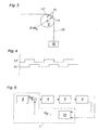
- Fig. 2 shows a section of a deflection roller 4 according to the invention, from which it can be seen that the deflection roller 4 has a plurality of holes 12 which are arranged at regular intervals, for example every 10 °, on a circular path K.
- the center M K of the circular path K lies on the axis of rotation D of the guide roller 4.
- the diameter d B of the holes 12 corresponds to half the distance A MB , the centers M B of the holes 12 from each other
- the measuring device two Sensors 11, 11 ' which may be formed, for example, as inductive proximity switches can, wherein, whenever a sensor 11 ', on the center of a bore 12th points, the second sensor 11, on the edge of a bore 12 shows. Because of these two shifted by 90 ° signals can from the succession of signals on the Direction of rotation, from the number of pulses to the position and from the number of pulses per second, the rotational speed of the pulley be closed.
- control device 6 comprises a controller 7, a measuring device 14 and optionally an input device 8.
- a target speed V SOLL for the winch 3 to the controller 7, for example via a joystick or via a radio remote control are specified.
- control deviation is calculated from the difference between the actual speed and the set speed and a winch 3 controlling hydraulic valve 9 is switched as a control variable before the characteristic of the hydraulic valve 9 is linearized.
- the subsequent rotational movement of the winch 3 in turn causes a rotational movement of the guide roller 4, the new actual position is detected in turn depending on the direction of the measuring device 14 in turn.
- the invention is not limited to the exemplary embodiments shown is limited.
- the preferably used PID controller could go through other electronic controllers are used.
- the essential feature of the invention is the detection of the rotational movement of the Pulley for the hoist rope at the tip of the boom in direction and size.
- a The basic idea of the invention thus represents the detection of the rotational movement of the deflection roller, which is closest to the load along the hoisting rope.
Landscapes
- Engineering & Computer Science (AREA)
- Mechanical Engineering (AREA)
- Automation & Control Theory (AREA)
- Control And Safety Of Cranes (AREA)
- Jib Cranes (AREA)
Abstract
Description
- Fig. 1
- ein Blockschema eines erfindungsgemäßen Kranes,
- Fig. 2 bis 4
- Details der Messeinrichtung zusammen mit der Umlenkrolle, und
- Fig. 5
- schematisch den Ablauf eines Regelvorganges.

Claims (9)
- Kran (1) mit einem teleskopierbaren, insbesondere knickbaren, Ausleger (2), einer Seilwinde (3) und einer an der Spitze des Auslegers (2) angeordneten Umlenkrolle (4) für ein Hubseil (13), an dem ein Lastaufnahmemittel (5), beispielsweise ein Haken, aufgehängt ist, und mit einer Regeleinrichtung zum Synchronisieren der Drehbewegung der Seilwinde (3) mit den Teleskop- bzw. Knickbewegungen des Auslegers (2), dadurch gekennzeichnet, dass der Kran (1) eine Messeinrichtung (14) zum Erfassen der Position bzw. der Umdrehungsgeschwindigkeit der Umlenkrolle (4) aufweist.
- Kran nach Anspruch 1, dadurch gekennzeichnet, dass die Messeinrichtung (14) zum Erfassen der Position bzw. der Umdrehungsgeschwindigkeit der Umlenkrolle (4), die der Last (10) am nächsten angeordnet ist, ausgebildet bzw. angeordnet ist.
- Kran nach einem der Ansprüche 1 oder 2, dadurch gekennzeichnet, dass die Regeleinrichtung (6) wenigstens einen elektronischen Regler (7), vorzugsweise einen PID-Regler, aufweist.
- Kran nach einem der Ansprüche 1 bis 3, dadurch gekennzeichnet, dass die Umlenkrolle (4) mehrere in regelmäßigen Abständen voneinander auf einer Kreisbahn (K) angeordnete Bohrungen (12) aufweist, wobei der Mittelpunkt (MK) der Kreisbahn auf der Drehachse (D) der Umlenkrolle (4) liegt.
- Kran nach Anspruch 4, dadurch gekennzeichnet, dass der Durchmesser (dB) der Bohrungen (12) dem halben Abstand (AMB), den die Mittelpunkte (MB) der Bohrungen (12) voneinander aufweisen, entspricht.
- Kran nach Anspruch 4 oder 5, dadurch gekennzeichnet, dass die Messeinrichtung (14) wenigstens zwei vorzugsweise induktive Sensoren (11, 11') zum Erfassen der Position der Bohrungen (12) aufweist.
- Verfahren zum Synchronisieren der Drehbewegung einer Seilwinde (3) mit den Teleskop- bzw. Knickbewegungen eines Auslegers (2) eines Kranes (1), wobei an der Spitze des Auslegers (2) eine Umlenkrolle (4) für ein Hubseil (13) angeordnet und an dem Hubseil (13) ein Lastaufnahmemittel (5), beispielsweise ein Haken, angeordnet ist, dadurch gekennzeichnet, dass die Seilbewegung an der Umlenkrolle (4) mittels einer Messeinrichtung (14) in Richtung und Größe erfasst und als Istwert einem Regler (7) weitergegeben wird.
- Verfahren nach Anspruch 7, dadurch gekennzeichnet, dass der Regler (7) in Abhängigkeit des erfassten Istwertes, vorzugsweise unter Berücksichtigung eines Sollwertes, eine Stellgröße für die Steuerung der Drehbewegung der Seilwinde (3) ermittelt, um die Änderung des Abstandes des Lastaufnahmemittels (5) von der Umlenkrolle (4) infolge einer Teleskop- bzw. einer Knickbewegung des Auslegers (2) zu kompensieren.
- Verfahren nach einem der Ansprüche 7 oder 8, dadurch gekennzeichnet, dass die Drehbewegung der Seilwinde (3) über ein Hydraulikventil (9) gesteuert wird.
Applications Claiming Priority (2)
| Application Number | Priority Date | Filing Date | Title |
|---|---|---|---|
| AT12802003 | 2003-08-14 | ||
| AT12802003 | 2003-08-14 |
Publications (1)
| Publication Number | Publication Date |
|---|---|
| EP1510497A1 true EP1510497A1 (de) | 2005-03-02 |
Family
ID=34085020
Family Applications (1)
| Application Number | Title | Priority Date | Filing Date |
|---|---|---|---|
| EP04017614A Withdrawn EP1510497A1 (de) | 2003-08-14 | 2004-07-26 | Kran mit einem teleskopierbaren Ausleger, einer Seilwinde und einer Regeleinrichtung |
Country Status (4)
| Country | Link |
|---|---|
| US (1) | US20050035077A1 (de) |
| EP (1) | EP1510497A1 (de) |
| JP (1) | JP2005060111A (de) |
| KR (1) | KR20050019034A (de) |
Cited By (3)
| Publication number | Priority date | Publication date | Assignee | Title |
|---|---|---|---|---|
| DE102011113208A1 (de) * | 2011-09-12 | 2013-03-14 | Liebherr-Werk Nenzing Gmbh | Seilwindenvorrichtung |
| IT201600108686A1 (it) * | 2016-10-27 | 2018-04-27 | O Me Fa S P A Officina Mecc Fassi | Dispositivo di supporto di un cavo di un verricello di una gru |
| IT202300016389A1 (it) * | 2023-08-02 | 2025-02-02 | Pm Oil & Steel S P A | Sistema di movimentazione di carichi sospesi |
Families Citing this family (10)
| Publication number | Priority date | Publication date | Assignee | Title |
|---|---|---|---|---|
| DE10233875B4 (de) * | 2002-07-25 | 2008-08-14 | Siemens Ag | Krananlage, insbesondere Containerkran |
| US7284743B1 (en) * | 2006-11-03 | 2007-10-23 | Columbus Mckinnon Corporation | Hoist limiting system |
| CA2792388C (en) | 2011-10-10 | 2020-01-14 | Wastequip, Llc | Hoist apparatus |
| CN104569471B (zh) * | 2015-02-11 | 2017-11-28 | 徐州重型机械有限公司 | 卷扬转速检测装置及方法 |
| JP6846541B2 (ja) * | 2017-12-14 | 2021-03-24 | 株式会社前田製作所 | 移動式クレーンのブーム旋回角度検出装置 |
| EP3502036A1 (de) | 2017-12-20 | 2019-06-26 | Cargotec Patenter AB | Kabelführungsvorrichtung |
| CN109279550B (zh) * | 2018-09-30 | 2020-11-24 | 中国十七冶集团有限公司 | 一种大跨径复杂环境下缆索吊装设备辅助装置 |
| CN110255379B (zh) * | 2019-05-30 | 2020-07-10 | 中联重科股份有限公司 | 吊臂的旁弯检测方法、系统和旁弯监控系统 |
| DK180746B1 (en) | 2020-08-18 | 2022-02-10 | Hmf Group As | Control system for cantilever crane and method for controlling a cantilever crane |
| CN113086853B (zh) * | 2021-04-09 | 2023-05-30 | 上海海事大学 | 一种桥吊同步和摆角检测装置及检测方法 |
Citations (5)
| Publication number | Priority date | Publication date | Assignee | Title |
|---|---|---|---|---|
| FR1492931A (fr) * | 1966-05-11 | 1967-08-25 | Grue à flèche télescopique | |
| US3601259A (en) * | 1968-12-26 | 1971-08-24 | Hyster Co | Crane construction |
| US3883859A (en) * | 1972-12-29 | 1975-05-13 | Edward F Ancheta | Load height indication |
| US4809857A (en) * | 1987-08-10 | 1989-03-07 | Fmc Corporation | Drum rotation indicator |
| EP1291312A2 (de) * | 2001-09-05 | 2003-03-12 | Allebroer Leo Alix De Lille | Vorrichtung zur Handhabung einer Last |
Family Cites Families (3)
| Publication number | Priority date | Publication date | Assignee | Title |
|---|---|---|---|---|
| FR2648584B1 (fr) * | 1989-06-16 | 1991-10-11 | Rexroth Sigma | Procede et systeme de regulation du courant moyen traversant une charge, et dispositif de telecommande electrique du type manipulateur en faisant application |
| JPH0626067A (ja) * | 1992-07-09 | 1994-02-01 | Kobe Steel Ltd | ディッパショベルの掘削制御装置 |
| US6547220B2 (en) * | 2000-01-31 | 2003-04-15 | Wilmington Research And Development Corporation | Open loop control with velocity threshold for pneumatic hoist |
-
2004
- 2004-07-26 EP EP04017614A patent/EP1510497A1/de not_active Withdrawn
- 2004-08-04 JP JP2004227987A patent/JP2005060111A/ja active Pending
- 2004-08-09 KR KR1020040062503A patent/KR20050019034A/ko not_active Withdrawn
- 2004-08-13 US US10/917,379 patent/US20050035077A1/en not_active Abandoned
Patent Citations (5)
| Publication number | Priority date | Publication date | Assignee | Title |
|---|---|---|---|---|
| FR1492931A (fr) * | 1966-05-11 | 1967-08-25 | Grue à flèche télescopique | |
| US3601259A (en) * | 1968-12-26 | 1971-08-24 | Hyster Co | Crane construction |
| US3883859A (en) * | 1972-12-29 | 1975-05-13 | Edward F Ancheta | Load height indication |
| US4809857A (en) * | 1987-08-10 | 1989-03-07 | Fmc Corporation | Drum rotation indicator |
| EP1291312A2 (de) * | 2001-09-05 | 2003-03-12 | Allebroer Leo Alix De Lille | Vorrichtung zur Handhabung einer Last |
Cited By (5)
| Publication number | Priority date | Publication date | Assignee | Title |
|---|---|---|---|---|
| DE102011113208A1 (de) * | 2011-09-12 | 2013-03-14 | Liebherr-Werk Nenzing Gmbh | Seilwindenvorrichtung |
| IT201600108686A1 (it) * | 2016-10-27 | 2018-04-27 | O Me Fa S P A Officina Mecc Fassi | Dispositivo di supporto di un cavo di un verricello di una gru |
| EP3315452A1 (de) * | 2016-10-27 | 2018-05-02 | O.ME.FA. S.p.A. Officina Meccanica Fassi | Vorrichtung zum tragen eines kabels einer winde eines krans |
| US10384916B2 (en) | 2016-10-27 | 2019-08-20 | O.ME.FA S.p.A. Officina Meccanica Fassi | Device for supporting a cable of a capstan of a crane |
| IT202300016389A1 (it) * | 2023-08-02 | 2025-02-02 | Pm Oil & Steel S P A | Sistema di movimentazione di carichi sospesi |
Also Published As
| Publication number | Publication date |
|---|---|
| JP2005060111A (ja) | 2005-03-10 |
| US20050035077A1 (en) | 2005-02-17 |
| KR20050019034A (ko) | 2005-02-28 |
Similar Documents
| Publication | Publication Date | Title |
|---|---|---|
| DE102011115224C5 (de) | Kran, insbesondere Raupen-oder Mobilkran | |
| EP3408211B1 (de) | Kran | |
| EP3489187B1 (de) | Klettersystem für einen kran | |
| DE102019122796A1 (de) | Kran und Verfahren zum Steuern eines solchen Krans | |
| WO2003040016A1 (de) | Fahrzeugkran mit superlifteinrichtung | |
| DE102016004350A1 (de) | Kran und Verfahren zum Steuern eines solchen Krans | |
| DE202010014310U1 (de) | Kran, insbesondere Raupen- oder Mobilkran | |
| DE19931301B4 (de) | Verfahren und Vorrichtung zum Führen eines Kranlasthakens | |
| DE2254485A1 (de) | Vorrichtung zum messen der vortriebsgeschwindigkeit einer von einer schwimmenden installation aus durchgefuehrten bohrung | |
| EP4017826B1 (de) | Steuereinheit und verfahren zum betrieb eines fördermittels | |
| EP3728099B1 (de) | Kransteuerung | |
| EP3336050B1 (de) | Flurförderzeug mit einer steuereinheit zur regelung der bewegung einer kolbenstange eines hydraulikzylinders sowie ein solches verfahren | |
| EP1722197B1 (de) | Verfahren und Vorrichtung zur Darstellung der Lage und des Bewegungszustands einer pendelfähigen Last | |
| DE19842436A1 (de) | Verfahren und Vorrichtung zur Kompensation der Verformung eines Kranauslegers bei dem Aufnehmen und Absetzen von Lasten | |
| WO2023025643A1 (de) | Turmdrehkran, verfahren und steuerungseinheit zum betreiben eines turmdrehkrans, laufkatze und katzfahrwerk | |
| EP0387399B1 (de) | Verfahren und Vorrichtung zur Steuerung der Kranfunktionen eines mobilen Teleskopauslegerkrans | |
| DE4405525A1 (de) | Kran mit einem Fahrantrieb zum horizontalen Verfahren einer an einem Seil hängenden Last | |
| DE19931303A1 (de) | Tragfähigkeitsoptimierung beim Ausführen von Kranbewegungen | |
| EP3697718B1 (de) | System zum bedienen eines lasthandling-krans sowie lasthandling-kran und verfahren zu dessen bedienung | |
| EP2897892B1 (de) | Verfahren zum betrieb eines krans und kran | |
| WO2024156497A1 (de) | Verfahren und vorrichtung zum betreiben eines auslegerdrehkrans sowie auslegerdrehkran | |
| DE3418923A1 (de) | Anlage zum versetzen von mauersteinen | |
| EP3722512B1 (de) | Tiefbaugerät und verfahren zum betreiben des tiefbaugeräts | |
| EP1472174B1 (de) | Kran mit handeingabeeinheiten | |
| EP3736244A1 (de) | Verfahren zum betreiben einer vorrichtung zum handgeführten bewegen von gegenständen |
Legal Events
| Date | Code | Title | Description |
|---|---|---|---|
| PUAI | Public reference made under article 153(3) epc to a published international application that has entered the european phase |
Free format text: ORIGINAL CODE: 0009012 |
|
| AK | Designated contracting states |
Kind code of ref document: A1 Designated state(s): AT BE BG CH CY CZ DE DK EE ES FI FR GB GR HU IE IT LI LU MC NL PL PT RO SE SI SK TR |
|
| AX | Request for extension of the european patent |
Extension state: AL HR LT LV MK |
|
| 17P | Request for examination filed |
Effective date: 20050214 |
|
| AKX | Designation fees paid |
Designated state(s): AT BE BG CH CY CZ DE DK EE ES FI FR GB GR HU IE IT LI LU MC NL PL PT RO SE SI SK TR |
|
| GRAP | Despatch of communication of intention to grant a patent |
Free format text: ORIGINAL CODE: EPIDOSNIGR1 |
|
| GRAC | Information related to communication of intention to grant a patent modified |
Free format text: ORIGINAL CODE: EPIDOSCIGR1 |
|
| GRAS | Grant fee paid |
Free format text: ORIGINAL CODE: EPIDOSNIGR3 |
|
| STAA | Information on the status of an ep patent application or granted ep patent |
Free format text: STATUS: THE APPLICATION IS DEEMED TO BE WITHDRAWN |
|
| 18D | Application deemed to be withdrawn |
Effective date: 20070405 |