EP1510498B1 - Procédé de surveillance d' un palan à chaine et palan à chaine - Google Patents
Procédé de surveillance d' un palan à chaine et palan à chaine Download PDFInfo
- Publication number
- EP1510498B1 EP1510498B1 EP04019121A EP04019121A EP1510498B1 EP 1510498 B1 EP1510498 B1 EP 1510498B1 EP 04019121 A EP04019121 A EP 04019121A EP 04019121 A EP04019121 A EP 04019121A EP 1510498 B1 EP1510498 B1 EP 1510498B1
- Authority
- EP
- European Patent Office
- Prior art keywords
- drive motor
- speed
- gearbox
- operating
- chain hoist
- Prior art date
- Legal status (The legal status is an assumption and is not a legal conclusion. Google has not performed a legal analysis and makes no representation as to the accuracy of the status listed.)
- Expired - Lifetime
Links
- 238000000034 method Methods 0.000 title claims description 14
- 238000012544 monitoring process Methods 0.000 title claims description 13
- 230000005540 biological transmission Effects 0.000 claims description 53
- 230000004888 barrier function Effects 0.000 claims description 4
- 238000005259 measurement Methods 0.000 claims 1
- 239000007787 solid Substances 0.000 claims 1
- 230000001419 dependent effect Effects 0.000 description 3
- 230000007257 malfunction Effects 0.000 description 3
- 238000001514 detection method Methods 0.000 description 2
- 238000012806 monitoring device Methods 0.000 description 2
- 238000005096 rolling process Methods 0.000 description 2
- 230000006978 adaptation Effects 0.000 description 1
- 230000006378 damage Effects 0.000 description 1
- 238000013461 design Methods 0.000 description 1
- 238000011156 evaluation Methods 0.000 description 1
- 238000013021 overheating Methods 0.000 description 1
- 230000004044 response Effects 0.000 description 1
- 238000004804 winding Methods 0.000 description 1
Images
Classifications
-
- B—PERFORMING OPERATIONS; TRANSPORTING
- B66—HOISTING; LIFTING; HAULING
- B66D—CAPSTANS; WINCHES; TACKLES, e.g. PULLEY BLOCKS; HOISTS
- B66D3/00—Portable or mobile lifting or hauling appliances
- B66D3/18—Power-operated hoists
- B66D3/20—Power-operated hoists with driving motor, e.g. electric motor, and drum or barrel contained in a common housing
- B66D3/22—Power-operated hoists with driving motor, e.g. electric motor, and drum or barrel contained in a common housing with variable-speed gearings between driving motor and drum or barrel
-
- B—PERFORMING OPERATIONS; TRANSPORTING
- B66—HOISTING; LIFTING; HAULING
- B66D—CAPSTANS; WINCHES; TACKLES, e.g. PULLEY BLOCKS; HOISTS
- B66D1/00—Rope, cable, or chain winding mechanisms; Capstans
- B66D1/28—Other constructional details
- B66D1/40—Control devices
- B66D1/48—Control devices automatic
- B66D1/485—Control devices automatic electrical
-
- B—PERFORMING OPERATIONS; TRANSPORTING
- B66—HOISTING; LIFTING; HAULING
- B66D—CAPSTANS; WINCHES; TACKLES, e.g. PULLEY BLOCKS; HOISTS
- B66D1/00—Rope, cable, or chain winding mechanisms; Capstans
- B66D1/54—Safety gear
Definitions
- the invention relates to a method for monitoring a chain hoist with an electric drive motor, which is connected on the output side via a slip clutch to a transmission.
- the invention also relates to a chain hoist with an electric drive motor, which is connected on the output side via a slip clutch to a transmission.
- chain hoists are generally known, the brake is arranged on the output shaft of the drive motor and thus before the slip clutch.
- an overload of the chain hoist, a faulty limit switch or a release of the brake not performed as a malfunction not only lead to a desired slipping of the slip clutch but also to their thermal overload. Depending on the design of the chain hoist, this may be too cause severe wear or destruction of the slip clutch or even crash the load.
- the drive chain here has a form-locking power transmission between an electric motor and a trained as a cable drum of a cable load application point.
- the cable drum is associated with an additional brake, which is actuated when a speed deviation between a first speed sensor associated with the electric motor and a second speed sensor associated with the cable drum is determined.
- the additional brake can thus prevent a load crash.
- This monitoring device does not provide to switch off the electric motor in case of interrupted force closure, as this just runs unloaded with interrupted power flow empty. Also here is the monitoring of the evaluation of two speed signals from two speed sensors. A deviation of the rotational speed of the electric motor from its operating data in the sense of an over or underspeed is not recognized by this monitoring device.
- the invention has for its object to provide a method for monitoring a chain hoist and a structurally simple chain hoist with a slip clutch that allow safe operation of the chain hoist.
- the object is achieved by a method having the features of claim 1 and by a chain hoist having the features of claim 7.
- the dependent claims 2 to 6 contain an advantageous embodiment of the method and the dependent claims 8 to 10 contain advantageous embodiments of the chain hoist.
- a safe operation of the chain hoist is achieved in a method for monitoring a chain hoist with an electric drive motor, the output side via a slip clutch with a transmission achieved by a sensor, the speed of the transmission is determined, the determined speed of the transmission in a control device is compared with the determined from operating data of the drive motor operating speed of the drive motor and upon detection of a deviation of the speed of the transmission is switched off from the operating speed, taking into account tolerances and, where appropriate, gear ratio of the transmission of the drive motor.
- a thermal overload of the slip clutch is particularly easy to avoid.
- a minimization of the wear of the slip clutch is to be achieved.
- an overload of the chain hoist can also be detected very quickly with a response time of less than one second via the sensor according to the invention.
- the invention requires only the use of a single speed sensor, since its measured value for the monitoring process is compared with a previously determined stored in the control device operating speed, which is characteristic of the current operating state.
- the deviations determined via the monitoring can be over or under speeds with respect to the stored operating speed, which usually result from malfunctions of the drive motor, the slip clutch, the transmission or the brake.
- the comparison of the speed of the transmission with the determined from operating data of the drive motor operating speed is particularly simple when the speed of the adjoining the slip clutch transmission input shaft is determined via the sensor. Since the sensor is arranged on the transmission input shaft, in addition to monitoring the slip clutch, this sensor can also detect malfunctions of a brake arranged on the transmission input shaft and thus overheating of the brake can be avoided.
- control device changes during operation of the chain hoist, in particular in a change between individual operating conditions, which changes from one to another operating speed.
- control device is adjustable or programmable with regard to the time periods required for a change between the respective operating states and the permissible operating speed to be reached within the assigned time periods. If, for example, a usual period for a run-up of the chain hoist from the slow lifting speed to the fast lifting speed is exceeded, the drive motor is switched off and, if necessary, the brake is activated. Even with these periods tolerances can be taken into account so as not to disturb the operation of the chain hoist.
- the comparison required for the monitoring is additionally simplified if the operating speeds stored or stored in the control device are in the form of operating speed ranges and thus already additionally contain the information about the permissible tolerance range with respect to the operating speed for the respective operating state. This also applies to the periods.
- a safe operation of the chain hoist is achieved according to the invention characterized in that a sensor is provided for detecting the rotational speed of the transmission, which is connected to a control device, the control device is connected to the drive motor and the control device compares the rotational speeds determined from the measured values from the sensor and the measured values or operating data of the drive motor, and a determination of a deviation of the rotational speed of the transmission from the engine rotational speed, taking into account tolerances and optionally transmission ratio of the transmission a shutdown of the drive motor conditionally.
- a simplification of the comparison of the rotational speed of the transmission with the engine rotational speed determined from operating data or measured values of the drive motor is achieved in that the sensor for determining the rotational speed of the transmission input shaft is arranged on the transmission input shaft adjoining the slip clutch.
- the senor is designed as a rotationally fixed on the transmission input shaft formed fan disc whose speed is determined by a light barrier.
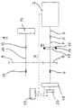
- FIG. 1 shows a schematic representation of the essential drive components of a chain hoist 1.
- the chain hoist 1 has an electric drive motor 2 with a protruding on the output side of the drive motor 2 motor shaft 3.
- the motor shaft 3 is arranged coaxially with a transmission input shaft 4 and rotatably connected thereto.
- the transmission input shaft 4 is mounted in the region of its ends via a first bearing 5 and a second bearing 6, which are preferably designed as rolling bearings.
- the transmission input shaft 4 is part of a transmission 7, which is formed in the present embodiment in one stage, but may well be multi-stage.
- the transmission 7 consists essentially of the transmission input shaft 4 between the bearing 5 and 6, a first gear 8 is arranged, which meshes with a second gear 9.
- This second gear 9 of the single gear stage of the transmission 7 is rotatably mounted on a transmission output shaft 10 which is mounted on both sides of the second gear 9 with a third bearing 11 and a fourth bearing 12, which are preferably designed as rolling bearings.
- the transmission input shaft 4 and the transmission output shaft 10 are here at a distance from each other and arranged parallel to each other.
- a rotationally fixed Sprocket 13 is arranged at one end of the transmission output shaft 10 arranged.
- This sprocket 13 is used in the usual way for the positive drive of the chain, not shown, of the chain 1, which enters after a successful lifting operation of the chain 1 of the sprocket 13 in a chain memory, not shown.
- a slip clutch 14 is arranged as overload protection.
- the slip clutch 14 consists essentially of a clutch disc 15 with an annular clutch lining 16, a pressure plate 17 and a spring element, not shown, for generating a bias between thrust washer 17 and clutch disc 15.
- the pressure plate 17 and clutch disc 15 are each rotatably on the in the slip clutch 14 interrupted transmission input shaft 4 is arranged.
- the spring element is provided, which preferably consists of abutting and arranged on the transmission input shaft spring washers.
- the package of the spring elements is supported on one side on the transmission input shaft 4 and on the other side on the first bearing. 5
- a sensor 18 for determining the rotational speed of the transmission input shaft 4 is arranged.
- the sensor 18 is preferably formed as a fan disk, not shown, which is arranged with the transmission input shaft 4 circumferentially at the end.
- a light barrier is arranged, via whose determined frequency of the light barrier interruption in a connected to the sensor 18 control device 19, the rotational speed of the transmission input shaft 4 is determined.
- a preferably electromagnetically actuated brake 20 is disposed on the transmission input shaft 4, which can be controlled via the control device 19.
- the conventionally disfiguring regions of operating speeds of the drive motor 2 are stored or stored in this control device 19 for a wide variety of operating states.
- operating states for example, standstill, high-speed lowering, low-speed lowering, high-speed lifting, low-speed lifting, switching between high and low speeds in hoisting and lowering, and raising or lowering from high or low speed to standstill understood to achieve the high or low speed.
- the currently applicable operating state results from the position of the operator switch for the drive motor 2.
- the self-adjusting ranges of operating speeds of the drive motor 2 are empirically determined for the motor types and network frequencies used in the usual way. A calculation is also possible.
- the control device 19 is adjustable or programmable with regard to the time periods required for a change between the operating states and the permissible operating speed ranges to be reached within the assigned time periods.
- the control device 19 can be set optimized for the various operating conditions. For example, a period of several hundred milliseconds (for example, 700 ms) may be provided for the slow lifting movement before the brake 20 and drive motor 2 are shut down to allow checking and adjustment of the slip clutch 14.
- the periods and operating speed ranges are chosen so that neither drive motor 2, brake 20 or slip clutch 14 are overloaded nor that an impermissible load movement can take place.
- the monitoring of the chain hoist 1 can also be dependent on the direction of rotation, d. H. in Hubrackinglander lowering, done.
- the control device 19 receives the control signal for the desired direction of movement of the load (lifting or lowering) via the unillustrated operating device for the chain hoist 1, the correspondence between the desired direction of movement and the actual direction of movement can be monitored.
- the control device 19 by comparing the speed of the transmission input shaft 4 with the stored in the control device 19 for the drive motor 2 operating speed range for each current operating state and now available Deviation detected and the control device 19 will immediately shut off the drive motor 2 and simultaneously control the brake 20 for the braking operation.
- a crash of the load can be successfully avoided.
- the brake 20 is arranged on the end of the transmission input shaft 4 facing away from the drive motor 2 and thus behind the slip clutch 14 when viewed from the drive motor 2.
- control device 19 is connected to the drive motor 2 and the brake 20 accordingly.
Landscapes
- Engineering & Computer Science (AREA)
- Mechanical Engineering (AREA)
- Control Of Electric Motors In General (AREA)
- Control Of Transmission Device (AREA)
- Transmission Devices (AREA)
- Braking Arrangements (AREA)
- Control And Safety Of Cranes (AREA)
Claims (10)
- Procédé de surveillance d'un palan à chaîne comportant un moteur d'entraînement électrique (2) qui est raccordé en sortie à un réducteur (7) par le biais d'un embrayage à friction (14),
caractérisé en ce que la vitesse du réducteur (7) est déterminée par un capteur (18), la vitesse déterminée du réducteur (7) est comparée, dans un dispositif de commande (19), à la vitesse de régime du moteur d'entraînement (2), déterminée à partir de données de fonctionnement du moteur d'entraînement (2) et, en cas d'écart entre la vitesse du réducteur (7) et la vitesse de régime, le moteur d'entraînement (2) est connecté en tenant compte des tolérances et éventuellement du rapport de démultiplication du réducteur (7). - Procédé selon la revendication 1, caractérisé en ce qu'un frein (20), relié au réducteur (7), est actionné en mode de freinage en même temps que l'on arrête le moteur d'entraînement (2).
- Procédé selon la revendication 1 ou 2, caractérisé en ce que la vitesse de l'arbre d'entrée (4) du réducteur, lequel arbre est raccordé à l'embrayage à friction (14), est déterminée par le capteur (18).
- Procédé selon l'une des revendications 1 à 3, caractérisé en ce que la vitesse de régime du moteur d'entraînement (2), laquelle est avantageusement déterminée empiriquement à partir de données de fonctionnement du moteur d'entraînement (2), est stockée respectivement mémorisée dans le dispositif de commande (19) pour différents états de fonctionnement du palan à chaîne (1).
- Procédé selon la revendication 4, caractérisé en ce que le dispositif de commande (19) peut être réglé respectivement programmé pour définir les laps de temps nécessaires au passage entre les états de fonctionnement respectifs, ainsi que la vitesse de régime qu'il est permis d'atteindre dans les laps de temps associés.
- Procédé selon la revendication 4 ou 5, caractérisé en ce que les vitesses de régime respectives sont stockées respectivement mémorisées dans le dispositif de commande (19) sous la forme de plages de vitesse de régime.
- Palan à chaîne comportant un moteur d'entraînement électrique (2), notamment en vue de mettre en oeuvre le procédé selon les revendications 1 à 6, lequel palan à chaîne est relié en sortie à un réducteur (7) par le biais d'un embrayage à friction (14),
caractérisé en ce qu'un capteur (18) est destiné à détecter la vitesse du réducteur (16) qui est relié à un dispositif de commande (19), en ce que le dispositif de commande (19) est relié au moteur d'entraînement (2) et en ce que les vitesses, déterminées à partir des valeurs de mesure provenant du capteur (18) et à partir des données de fonctionnement du moteur d'entraînement (2), peuvent être comparées par le dispositif de commande (19) et une détermination d'un écart entre la vitesse du réducteur (16) et la vitesse du moteur conditionne un arrêt du moteur d'entraînement (2) en tenant compte de tolérances et éventuellement du rapport de démultiplication du réducteur (7). - Palan à chaîne selon la revendication 7, caractérisé en ce qu'un frein (20), relié en sortie au réducteur (7), est actionné en mode de freinage en même temps que l'on arrête le moteur d'entraînement (2).
- Palan à chaîne selon la revendication 7 ou 8, caractérisé en ce que le capteur (18), destiné à déterminer la vitesse de l'arbre d'entrée (4) du réducteur, est placé au niveau de l'arbre d'entrée (4) du réducteur qui est raccordé à l'embrayage à friction (14).
- Palan à chaîne selon l'une des revendications 7 à 9, caractérisé en ce que le capteur (18) est conformé en rondelle en éventail conformée fixe en rotation sur l'arbre d'entrée (4) du réducteur dont la vitesse est déterminée par une barrière lumineuse.
Applications Claiming Priority (2)
| Application Number | Priority Date | Filing Date | Title |
|---|---|---|---|
| DE10339440A DE10339440A1 (de) | 2003-08-25 | 2003-08-25 | Verfahren zur Überwachung eines Kettenzuges und Kettenzug |
| DE10339440 | 2003-08-25 |
Publications (2)
| Publication Number | Publication Date |
|---|---|
| EP1510498A1 EP1510498A1 (fr) | 2005-03-02 |
| EP1510498B1 true EP1510498B1 (fr) | 2007-03-21 |
Family
ID=34089214
Family Applications (1)
| Application Number | Title | Priority Date | Filing Date |
|---|---|---|---|
| EP04019121A Expired - Lifetime EP1510498B1 (fr) | 2003-08-25 | 2004-08-12 | Procédé de surveillance d' un palan à chaine et palan à chaine |
Country Status (4)
| Country | Link |
|---|---|
| US (1) | US7422542B2 (fr) |
| EP (1) | EP1510498B1 (fr) |
| CN (1) | CN100542941C (fr) |
| DE (2) | DE10339440A1 (fr) |
Cited By (1)
| Publication number | Priority date | Publication date | Assignee | Title |
|---|---|---|---|---|
| DE102022122034A1 (de) | 2022-08-31 | 2024-02-29 | Konecranes Global Corporation | Verfahren zur Überwachung eines Kettenzugs |
Families Citing this family (10)
| Publication number | Priority date | Publication date | Assignee | Title |
|---|---|---|---|---|
| DE102007019959B3 (de) | 2007-04-27 | 2008-07-03 | Demag Cranes & Components Gmbh | Steuerungsanordnung zum parallelen Betreiben von mindestens zwei Kettenzügen |
| CN102674184B (zh) * | 2007-06-11 | 2015-07-08 | 索尤若驱动有限及两合公司 | 用于安全运行设备的配置结构、模块及方法 |
| US9802787B2 (en) * | 2013-09-20 | 2017-10-31 | Reel Power Licensing Corp. | Method of providing a clutch for a spool |
| FR3020804B1 (fr) * | 2014-05-06 | 2019-06-28 | Reel | Treuil modulaire embarque |
| CN104444901B (zh) * | 2014-12-10 | 2017-03-15 | 中曼石油钻井技术有限公司 | 一种石油钻机双档绞车电子差速控制系统及控制方法 |
| DE102015102140A1 (de) | 2015-02-13 | 2016-08-18 | Terex MHPS IP Management GmbH | Anordnung aus einem elektrischen Antriebsmotor, einem Getriebe und einem Drehgeber, insbesondere für einen Seilzug |
| CN107395557B (zh) * | 2017-03-28 | 2020-05-15 | 创新先进技术有限公司 | 一种业务请求的处理方法及装置 |
| US20190287107A1 (en) * | 2018-03-15 | 2019-09-19 | International Business Machines Corporation | Resource equity for blockchain |
| CN111056471B (zh) * | 2020-03-03 | 2024-08-16 | 宝鸡巨菱钻采设备有限责任公司 | 一种基于交流变频电动绞车的石油钻机用提升装置 |
| CA3153573A1 (fr) * | 2021-04-01 | 2022-10-01 | Breeze-Eastern Llc | Systeme de levage et procede de mise en oeuvre de detection de glissement |
Family Cites Families (15)
| Publication number | Priority date | Publication date | Assignee | Title |
|---|---|---|---|---|
| US2605313A (en) * | 1946-03-09 | 1952-07-29 | Vaughan Crane Company Ltd | Electric crane and the like |
| DE1556374A1 (de) * | 1968-02-21 | 1970-04-09 | Demag Kampnagel Gmbh | Winde,insbesondere Hangerwinde |
| US4175727A (en) * | 1978-03-06 | 1979-11-27 | Ederer Incorporated | Single failure proof crane |
| US4493479A (en) * | 1980-11-07 | 1985-01-15 | Ederer Incorporated | Hoist drive safety system |
| CH660173A5 (de) * | 1982-05-03 | 1987-03-31 | Inventio Ag | Antriebssteuerung fuer einen aufzug. |
| US4636962A (en) * | 1983-05-24 | 1987-01-13 | Columbus Mckinnon Corporation | Microprocessor-controlled hoist system |
| CN2061167U (zh) * | 1988-08-07 | 1990-08-29 | 尧进先 | 绞车、电机车速度监测保护仪 |
| DE3838058C3 (de) * | 1988-11-07 | 1996-04-11 | Mannesmann Ag | Antriebsüberwachung einer Antriebskette |
| DE59101661D1 (de) * | 1990-09-21 | 1994-06-23 | Siemens Ag | Sicherheitsvorrichtung für Krane. |
| TW348169B (en) * | 1994-11-15 | 1998-12-21 | Inventio Ag | Evacuation system for a lift cage |
| DE19927847C1 (de) * | 1999-06-18 | 2000-10-12 | Hoffmann Foerdertechnik Gmbh W | Lastsicherndes Bremskupplungssystem für kraftangetriebene Hebezeuge, insbesondere für Elektrokettenzüge |
| CN1151953C (zh) * | 2001-07-23 | 2004-06-02 | 连云港中海集装箱码头有限公司 | 过加速保护装置 |
| DE10244865B4 (de) * | 2002-09-23 | 2004-09-30 | Demag Cranes & Components Gmbh | Kettenzug |
| US7063306B2 (en) * | 2003-10-01 | 2006-06-20 | Paccar Inc | Electronic winch monitoring system |
| WO2005042393A2 (fr) * | 2003-10-16 | 2005-05-12 | American Crane & Equipment Corporation | Systeme de diagnostic pour grues |
-
2003
- 2003-08-25 DE DE10339440A patent/DE10339440A1/de not_active Withdrawn
-
2004
- 2004-08-12 EP EP04019121A patent/EP1510498B1/fr not_active Expired - Lifetime
- 2004-08-12 DE DE502004003259T patent/DE502004003259D1/de not_active Expired - Lifetime
- 2004-08-24 US US10/925,310 patent/US7422542B2/en active Active
- 2004-08-25 CN CN200410068235.0A patent/CN100542941C/zh not_active Expired - Lifetime
Cited By (3)
| Publication number | Priority date | Publication date | Assignee | Title |
|---|---|---|---|---|
| DE102022122034A1 (de) | 2022-08-31 | 2024-02-29 | Konecranes Global Corporation | Verfahren zur Überwachung eines Kettenzugs |
| WO2024047049A1 (fr) | 2022-08-31 | 2024-03-07 | Konecranes Global Corporation | Procédé de surveillance d'un palan à chaîne |
| US12522481B2 (en) | 2022-08-31 | 2026-01-13 | Konecranes Global Corporation | Method for monitoring a chain hoist |
Also Published As
| Publication number | Publication date |
|---|---|
| EP1510498A1 (fr) | 2005-03-02 |
| US20050065692A1 (en) | 2005-03-24 |
| US7422542B2 (en) | 2008-09-09 |
| DE502004003259D1 (de) | 2007-05-03 |
| CN100542941C (zh) | 2009-09-23 |
| DE10339440A1 (de) | 2005-04-07 |
| CN1590274A (zh) | 2005-03-09 |
Similar Documents
| Publication | Publication Date | Title |
|---|---|---|
| EP1661845B1 (fr) | Dispositif de levage et procédé d'utiliser ce dispositif | |
| EP2846037B1 (fr) | Procédé de fonctionnement d'une éolienne et éolienne | |
| EP2088314B1 (fr) | Dispositif pour la surveillance de la vitesse de rotation d'une éolienne | |
| EP1881312B1 (fr) | Banc d'essai à rouleaux d'un frein | |
| EP1510498B1 (fr) | Procédé de surveillance d' un palan à chaine et palan à chaine | |
| EP2805863B1 (fr) | Chaîne cinématique d'un véhicule ferroviaire et procédé de détection d'un cas de surcharge d'une chaîne cinématique | |
| DE3437808C2 (de) | Verfahren zum lastabhängigen Auslösen einer Sicherheitskupplung an einer Maschinenanlage und Drehmomentüberwachungssystem zur Durchführung des Verfahrens | |
| EP2254784A1 (fr) | Système de surveillance de l usure, équipement de transport à traction par câble et procédé de surveillance des pièces d usure de celui-ci | |
| EP0006976B1 (fr) | Dispositif de retenue pour ascenseurs et funiculaires | |
| DE102018126964A1 (de) | Bremsanordnung zur sicherung einer fördereinrichtung, fördereinrichtung und krananlage | |
| DE102022212649A1 (de) | Lenkantrieb für ein Lenksystem eines Kraftfahrzeugs, Verfahren zum Betrieb eines Lenkantriebs, Lenksystem für ein Kraftfahrzeug und Verfahren zum Betrieb eines Lenksystems | |
| DE3933505A1 (de) | Hubwerk | |
| EP0077890B1 (fr) | Palan électrique à chaîne | |
| EP4499557B1 (fr) | Procédé de surveillance d'un palan à chaîne | |
| EP2219984B1 (fr) | Entraînement d'ascenseur et procédé d'entraînement et d'arrêt d'une cabine d'ascenseur, procédé correspondant, et système de freinage et procédé de freinage et d'arrêt d'une cabine d'ascenseur et procédé correspondant | |
| DE19536918C1 (de) | Überwachungseinrichtung für den Antrieb einer Druckmaschine | |
| DE102022130859B4 (de) | Verfahren zum Betrieb eines Antriebssystems zur Vermeidung von Eingriffsstörungen in Spannungswellengetrieben | |
| DE3632962C1 (en) | Control device for the brake and/or drive of a conveying system | |
| DE10148408C1 (de) | Sicherheitsbremse für einen Elektrokettenzug | |
| EP2981716B1 (fr) | Procédé et dispositif permettant de coupler et/ou de découpler un entraînement auxiliaire de transmission, éolienne | |
| DE102020124135A1 (de) | Verfahren und Vorrichtung zum Steuern eines Bremsvorgangs in einem Antriebsstrang | |
| DE19905020A1 (de) | Verfahren zur ständigen Überwachung der ordnungsgemäßen Betriebsfunktion eines Kranes | |
| EP1985574B1 (fr) | Agencement de commande destiné au fonctionnement parallèle d'au moins deux palans à chaînes | |
| EP1960852A1 (fr) | Dispositif de contrôle et procédé de contrôle d un dispositif de commande | |
| DE102005027338B4 (de) | Verfahren zum Betrieb der Systemanordnung eines Hubwerkes |
Legal Events
| Date | Code | Title | Description |
|---|---|---|---|
| PUAI | Public reference made under article 153(3) epc to a published international application that has entered the european phase |
Free format text: ORIGINAL CODE: 0009012 |
|
| AK | Designated contracting states |
Kind code of ref document: A1 Designated state(s): AT BE BG CH CY CZ DE DK EE ES FI FR GB GR HU IE IT LI LU MC NL PL PT RO SE SI SK TR |
|
| AX | Request for extension of the european patent |
Extension state: AL HR LT LV MK |
|
| 17P | Request for examination filed |
Effective date: 20050324 |
|
| AKX | Designation fees paid |
Designated state(s): CH DE FI FR GB IT LI |
|
| GRAP | Despatch of communication of intention to grant a patent |
Free format text: ORIGINAL CODE: EPIDOSNIGR1 |
|
| GRAS | Grant fee paid |
Free format text: ORIGINAL CODE: EPIDOSNIGR3 |
|
| GRAA | (expected) grant |
Free format text: ORIGINAL CODE: 0009210 |
|
| AK | Designated contracting states |
Kind code of ref document: B1 Designated state(s): CH DE FI FR GB IT LI |
|
| REG | Reference to a national code |
Ref country code: GB Ref legal event code: FG4D Free format text: NOT ENGLISH |
|
| REG | Reference to a national code |
Ref country code: CH Ref legal event code: EP |
|
| REF | Corresponds to: |
Ref document number: 502004003259 Country of ref document: DE Date of ref document: 20070503 Kind code of ref document: P |
|
| REG | Reference to a national code |
Ref country code: CH Ref legal event code: NV Representative=s name: PA ALDO ROEMPLER |
|
| GBT | Gb: translation of ep patent filed (gb section 77(6)(a)/1977) |
Effective date: 20070530 |
|
| ET | Fr: translation filed | ||
| PLBE | No opposition filed within time limit |
Free format text: ORIGINAL CODE: 0009261 |
|
| STAA | Information on the status of an ep patent application or granted ep patent |
Free format text: STATUS: NO OPPOSITION FILED WITHIN TIME LIMIT |
|
| 26N | No opposition filed |
Effective date: 20071227 |
|
| REG | Reference to a national code |
Ref country code: CH Ref legal event code: PCAR Free format text: ALDO ROEMPLER PATENTANWALT;BRENDENWEG 11 POSTFACH 154;9424 RHEINECK (CH) |
|
| REG | Reference to a national code |
Ref country code: DE Ref legal event code: R081 Ref document number: 502004003259 Country of ref document: DE Owner name: KONECRANES GLOBAL CORPORATION, FI Free format text: FORMER OWNER: DEMAG CRANES COMPONENTS GMBH, 58300 WETTER, DE Ref country code: DE Ref legal event code: R081 Ref document number: 502004003259 Country of ref document: DE Owner name: KONECRANES GLOBAL CORP., FI Free format text: FORMER OWNER: DEMAG CRANES & COMPONENTS GMBH, 58300 WETTER, DE Ref country code: DE Ref legal event code: R082 Ref document number: 502004003259 Country of ref document: DE Representative=s name: MOSER GOETZE & PARTNER PATENTANWAELTE MBB, DE Ref country code: DE Ref legal event code: R081 Ref document number: 502004003259 Country of ref document: DE Owner name: TEREX MHPS GMBH, DE Free format text: FORMER OWNER: DEMAG CRANES & COMPONENTS GMBH, 58300 WETTER, DE Ref country code: DE Ref legal event code: R081 Ref document number: 502004003259 Country of ref document: DE Owner name: KONECRANES GLOBAL CORPORATION, FI Free format text: FORMER OWNER: DEMAG CRANES & COMPONENTS GMBH, 58300 WETTER, DE |
|
| REG | Reference to a national code |
Ref country code: FR Ref legal event code: PLFP Year of fee payment: 13 |
|
| REG | Reference to a national code |
Ref country code: FR Ref legal event code: PLFP Year of fee payment: 14 |
|
| REG | Reference to a national code |
Ref country code: DE Ref legal event code: R081 Ref document number: 502004003259 Country of ref document: DE Owner name: KONECRANES GLOBAL CORP., FI Free format text: FORMER OWNER: TEREX MHPS GMBH, 40597 DUESSELDORF, DE Ref country code: DE Ref legal event code: R082 Ref document number: 502004003259 Country of ref document: DE Representative=s name: MOSER GOETZE & PARTNER PATENTANWAELTE MBB, DE Ref country code: DE Ref legal event code: R081 Ref document number: 502004003259 Country of ref document: DE Owner name: KONECRANES GLOBAL CORPORATION, FI Free format text: FORMER OWNER: TEREX MHPS GMBH, 40597 DUESSELDORF, DE |
|
| REG | Reference to a national code |
Ref country code: CH Ref legal event code: PUE Owner name: KONECRANES GLOBAL CORPORATION, FI Free format text: FORMER OWNER: DEMAG CRANES AND COMPONENTS GMBH, DE |
|
| REG | Reference to a national code |
Ref country code: GB Ref legal event code: 732E Free format text: REGISTERED BETWEEN 20180531 AND 20180606 |
|
| REG | Reference to a national code |
Ref country code: FR Ref legal event code: PLFP Year of fee payment: 15 |
|
| PGFP | Annual fee paid to national office [announced via postgrant information from national office to epo] |
Ref country code: FR Payment date: 20190822 Year of fee payment: 16 Ref country code: FI Payment date: 20190822 Year of fee payment: 16 |
|
| PGFP | Annual fee paid to national office [announced via postgrant information from national office to epo] |
Ref country code: GB Payment date: 20190821 Year of fee payment: 16 |
|
| REG | Reference to a national code |
Ref country code: FI Ref legal event code: MAE |
|
| GBPC | Gb: european patent ceased through non-payment of renewal fee |
Effective date: 20200812 |
|
| PG25 | Lapsed in a contracting state [announced via postgrant information from national office to epo] |
Ref country code: FI Free format text: LAPSE BECAUSE OF NON-PAYMENT OF DUE FEES Effective date: 20200812 |
|
| PG25 | Lapsed in a contracting state [announced via postgrant information from national office to epo] |
Ref country code: FR Free format text: LAPSE BECAUSE OF NON-PAYMENT OF DUE FEES Effective date: 20200831 |
|
| PG25 | Lapsed in a contracting state [announced via postgrant information from national office to epo] |
Ref country code: GB Free format text: LAPSE BECAUSE OF NON-PAYMENT OF DUE FEES Effective date: 20200812 |
|
| P01 | Opt-out of the competence of the unified patent court (upc) registered |
Effective date: 20230502 |
|
| PGFP | Annual fee paid to national office [announced via postgrant information from national office to epo] |
Ref country code: IT Payment date: 20230825 Year of fee payment: 20 Ref country code: CH Payment date: 20230902 Year of fee payment: 20 |
|
| PGFP | Annual fee paid to national office [announced via postgrant information from national office to epo] |
Ref country code: DE Payment date: 20230821 Year of fee payment: 20 |
|
| REG | Reference to a national code |
Ref country code: DE Ref legal event code: R071 Ref document number: 502004003259 Country of ref document: DE |
|
| REG | Reference to a national code |
Ref country code: CH Ref legal event code: PL |