EP1510632A2 - Dispositif d'écoulement - Google Patents
Dispositif d'écoulement Download PDFInfo
- Publication number
- EP1510632A2 EP1510632A2 EP04405523A EP04405523A EP1510632A2 EP 1510632 A2 EP1510632 A2 EP 1510632A2 EP 04405523 A EP04405523 A EP 04405523A EP 04405523 A EP04405523 A EP 04405523A EP 1510632 A2 EP1510632 A2 EP 1510632A2
- Authority
- EP
- European Patent Office
- Prior art keywords
- tube
- drainage device
- fine filter
- holes
- diaphragm
- Prior art date
- Legal status (The legal status is an assumption and is not a legal conclusion. Google has not performed a legal analysis and makes no representation as to the accuracy of the status listed.)
- Withdrawn
Links
Images


Classifications
-
- E—FIXED CONSTRUCTIONS
- E04—BUILDING
- E04D—ROOF COVERINGS; SKY-LIGHTS; GUTTERS; ROOF-WORKING TOOLS
- E04D13/00—Special arrangements or devices in connection with roof coverings; Protection against birds; Roof drainage ; Sky-lights
- E04D13/04—Roof drainage; Drainage fittings in flat roofs, balconies or the like
- E04D13/0404—Drainage on the roof surface
- E04D13/0409—Drainage outlets, e.g. gullies
-
- E—FIXED CONSTRUCTIONS
- E04—BUILDING
- E04D—ROOF COVERINGS; SKY-LIGHTS; GUTTERS; ROOF-WORKING TOOLS
- E04D13/00—Special arrangements or devices in connection with roof coverings; Protection against birds; Roof drainage ; Sky-lights
- E04D13/04—Roof drainage; Drainage fittings in flat roofs, balconies or the like
- E04D13/0404—Drainage on the roof surface
- E04D13/0409—Drainage outlets, e.g. gullies
- E04D2013/0427—Drainage outlets, e.g. gullies with means for controlling the flow in the outlet
Definitions
- the invention relates to a drain device for the throttled drain of rainwater according to the generic term of claim 1
- the building permit authorities require in urban areas of the developers, the rainwater of sealed surfaces on its own grounds seep into let and with this measure the groundwater to enrich and the sewer or sewage treatment plants to relieve.
- This requirement is not just about water of sealed areas such as squares, but also of Roof surfaces.
- Rainwater from sealed places like Parking lots and streets must inevitably in the accumulating amount to be derived immediately to one To avoid accumulation.
- the on roofs falling rainfall due to suitable roofing, especially the flat roofs, or the creation of Reservoir temporarily stored and in the desired Amount be dissipated over a longer period.
- Rainwater-storing roofs become retention roofs called and they can either be used as nude roofs or as Substrate-covered flat roofs with or without greening be educated.
- Substrate covered flat roofs can in limited mass in the pores of the substrate temporarily absorb, store and recover water let drain.
- Known substrates store in their Pores about one third of their own volume. In order therefore To be able to store 50 liters of water per square meter, it needs a substrate volume of about 16 cm in height. The Outflow delay is about five, depending on the substrate structure Hours. After this time, the pores are emptied and that Substrate dries out. In heavy rain, the temporal Absorbent capacity of the substrate often not to the withhold the amount of rainfall. This particular when heavy rainfall on a substrate with already water-saturated Pores fall.
- the percolation surface should be about 5% of the roof area.
- a larger retention volume on the roof and a low drainage volume can reduce the seepage area accordingly. This can be reduced, for example, in a detached house with 200m 2 roof area to a 1m 2 .
- the known throttle devices which allow such low flow rates, require a high level of maintenance, since their dirt and clogging vulnerability of the small diameter of the aperture is very large.
- Object of the present invention is to provide a Drain device, which has a very small drainage amount per Unit of time, without being affected by suspended matter, Leaves etc. the corresponding small aperture of Drainage device clogged and thus their function can be affected.
- the inventive Device requires a small cleaning effort, since the cross-sectional area of the upstream filter device is many times greater than the flow rate determining aperture and also optimal Has self-cleaning properties.
- the filter can manually cleaned if necessary without much effort or be completely exchanged.
- the drainage device exists from a few individual parts, which are tool-free during assembly can be put together on the roof.
- the pinhole exists from a pipe, which in the on-site existing, at the roof surface ending drain pipe can be inserted and can be sealed by lip seals.
- the pinhole only in the drain pipe is inserted, its height or the height of the first row of holes on more if necessary be aligned similar drainage devices, so that at the same time in all drain devices the Water flow starts or larger amounts of water evenly distributed over the drainage devices be derived.
- an additional pipe put on be, on which a thread is formed, which with a thread on the orifice tube or one above arranged additional threaded pipe combs.
- the height of the aperture tube by turning the the latter.
- An over the aperture tube arranged lid which is located at a distance from the upper edge of the diaphragm tube and this projects radially, and one on the aperture tube mounted flange whose diameter with the Diameter of the lid approximately matches be achieved that at the beginning of the overflow no Sucking occurs and also a high suction power is guaranteed.
- the water inlet openings are arranged in the aperture tube so that they do not diagonally opposite one another at the same height, one becomes significant noise reduction during operation of the Drainage device reached.
- the pinhole and preferably made of a plastic or a metallic fabric produced filter are covered by an opaque hood, so that no UV light will damage the components and through Incidence of light can promote the growth of algae and moss.
- the almost complete darkening of the filter area of the Roof drain prevents the rainwater persistent contaminants and dissolved Fertilizers such as ammonia from agriculture, Nitrogen from combustion processes etc. as well as organic Suspended matter such as pollen, pollen etc. none Biorasen Guess or Vermosung form.
- the production the drainage device can be inexpensive in plastic, Metal or a combination of these materials. Due to the small cross sections of the slits in the hat, which covers the pipe aperture, air circulation the hot air by convection in the drain pipe almost completely prevents, especially if the slits in the hat partially or completely covered by pent-up water.
- this extended area 7 is a cylindrical in the example Aperture tube 9, at its lower end circumferential Lip seals 11 are arranged and at the top End a plurality of holes or holes 13 preferably in a regular arrangement next- and are embedded on top of each other (see the settlement in Figures 6 and 7).
- the upper edge of the diaphragm tube 9 is at the height of a3.
- a carrier 15 Concentric with the diaphragm 9 is a carrier 15, comprising a central ring 17 which extends over only about twenty percent of the section above the roof 1 of the aperture tube 9 extends.
- the central ring 17 At the central ring 17 are For example, four connecting webs 19 (see FIG. attached, which extend radially outwards and there are connected with ring sections 21.
- the ring sections 21 extend from the roof surface to the height a3.
- a support ring 25 This can be connected to the ring sections 21 or in one piece be prepared or put on this.
- the ring sections 21 and the support ring 25 made in one piece.
- in the Support ring 25 are a plurality of recesses 27th admitted.
- the carrier 15 can with a Attachment means 47, e.g. Screw and nut, on Aperture 9 to be attached.
- a cylindrical Fine filter 23 This is preferably dimensionally stable and consists of a fine metal or plastic grid or braid.
- the fine filter 23 may be tubular or be made without seam or made of a tubular rectangular lattice piece joined together to form a tube be.
- the fine filter 23 is two at the top and bottom applied O-rings 29 or a metal strap attached. Alternatively, the attachment of the fine filter 23 also be done with Briden or the like.
- the tubular fine filter 23 projects beyond the lower O-ring such that it as a flange-like protuberance 24 on the Surface of the roof rests (see Figure 4).
- a hat 31 This includes one cylindrical or polygonal jacket 33, at the Lower edge of a plurality of vertically extending Slots 35 are recessed.
- the hat 31 is on top a frusto-conical cover 37 completely closed. Inside the jacket 33 can clamp and Holding means 39 to be formed, which the hat 31 with respect a flange 41 at the upper edge of the support ring 25th center and hold the hat 31.
- the access of the water takes place always through the slots 35 in the jacket 33 of the hat 31st Through the slots 35 are larger impurities such Leaves and branches withheld. This rough Impurities can be lifted without lifting the hat 31 be eliminated. Finer impurities, such as pollen or leaf sections that just the slots 35 can happen, are stopped at the fine filter 23.
- Whose Surface is in the example shown about five times big as the surface of the aperture tube 9.
- the Water level within the roof outlet 3 always corresponds about that outside.
- the through the fine filter 23rd passed water is free of impurities, which are always larger than the holes 13 in the diaphragm tube. 9 Consequently, the holes 13 always remain continuous and ensure the specified calibrated outflow.
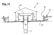
- a threaded tube 48 attached to the upper end 7 of the drain pipe 5, at which a flange 8 may be fixed, a threaded tube 48 attached.
- a threaded tube 48 is attached at the lower end of the Threaded tube 48 also a flange 8 'attached, over which secured by means of screws 10, the threaded tube 48 can be.
- a External thread 50 is formed, with an internal thread a Stülprohres 49 meshes.
- the upper end of the Stülprohres 49 carries the aperture tube 9, which at its upper edge is surrounded by an outwardly directed flange 55.
- an external thread and on Threaded tube 48 an inwardly directed thread 50.
- About the aperture tube 9 with the flange 55 is spaced a Cover 52.
- the diameter of the lid 52 corresponds to is essential to that of the flange 55 and much larger than the diameter of the aperture tube.
- Between the lid 52 and the flange 55 results thereby a suction slot 51, through the water at Exceeding the level a3 enter the diaphragm tube 9 can.
- By turning the lid 52 by suitable Spacer is connected to the flange 55, the Height of the upper edge of the aperture tube 9 (height a3) on and be adjusted.
- the Holes 13 are arranged in the aperture tube such that the there entering water jets 53 are not in the Center frontally meet, but diagonally opposite to the Wall to be redirected.
- the holes 13 are therefore offset accordingly on the circumference and / or in height arranged.
- the level of the withheld Rainwater on the roof 1 always to a minimum Lower and thereby set the fine filter 23 dry.
- self-cleaning of the Filters 23 instead, leaving this for a long time without mechanical cleaning or replacement fully operational remains.
- a clogging of the filter occurs 23 never suddenly, but gradually from bottom to bottom above, so that it is visible from the outside, that the accumulation height, as shown for example in Figure 2 with Arrow 45 is indicated on the outside of the hat 31, something rises. If the accumulation height exceeds the specified one essentially, so can by lifting the hat 31 and Removing the O-rings 29 of the fine filter 23 dissolved and either cleaned or replaced.
- the drain device not only be used on flat roofs, but also in Rainwater collection basin, where rainwater from Steep roofs or non-stowable other areas temporarily withheld and calibrated to one Seepage is to be passed.
Landscapes
- Engineering & Computer Science (AREA)
- Architecture (AREA)
- Civil Engineering (AREA)
- Structural Engineering (AREA)
- Tents Or Canopies (AREA)
- Sink And Installation For Waste Water (AREA)
Applications Claiming Priority (2)
| Application Number | Priority Date | Filing Date | Title |
|---|---|---|---|
| CH14332003 | 2003-08-21 | ||
| CH14332003 | 2003-08-21 |
Publications (2)
| Publication Number | Publication Date |
|---|---|
| EP1510632A2 true EP1510632A2 (fr) | 2005-03-02 |
| EP1510632A3 EP1510632A3 (fr) | 2006-04-05 |
Family
ID=34085316
Family Applications (1)
| Application Number | Title | Priority Date | Filing Date |
|---|---|---|---|
| EP04405523A Withdrawn EP1510632A3 (fr) | 2003-08-21 | 2004-08-20 | Dispositif d'écoulement |
Country Status (1)
| Country | Link |
|---|---|
| EP (1) | EP1510632A3 (fr) |
Cited By (3)
| Publication number | Priority date | Publication date | Assignee | Title |
|---|---|---|---|---|
| WO2010128283A3 (fr) * | 2009-05-05 | 2011-02-17 | Ove Arup & Partners International Limited | Système de collecte d'eau de pluie |
| EP2369088A1 (fr) * | 2010-03-25 | 2011-09-28 | Geberit International AG | Dispositif destiné au drainage des eaux pluviales de toit |
| CN102587597A (zh) * | 2012-03-30 | 2012-07-18 | 重庆大学 | 基于低影响开发思想的建筑平屋顶雨水立管安装结构及安装方法 |
Family Cites Families (5)
| Publication number | Priority date | Publication date | Assignee | Title |
|---|---|---|---|---|
| US2701644A (en) * | 1952-03-07 | 1955-02-08 | Edgar J Griffiths | Filter with medium supported by suction piping |
| US3469698A (en) * | 1967-04-05 | 1969-09-30 | Josam Mfg Co | Controlled flow drain |
| US3517813A (en) * | 1968-09-16 | 1970-06-30 | Kunibert Thaler | Roof drain |
| US3529723A (en) * | 1968-11-07 | 1970-09-22 | Charles L Hagedorn | Roof drain |
| FR2791722B1 (fr) * | 1999-04-01 | 2001-04-27 | Pont A Mousson | Dispositif d'evacuation des eaux pluviales a debit regule |
-
2004
- 2004-08-20 EP EP04405523A patent/EP1510632A3/fr not_active Withdrawn
Cited By (7)
| Publication number | Priority date | Publication date | Assignee | Title |
|---|---|---|---|---|
| WO2010128283A3 (fr) * | 2009-05-05 | 2011-02-17 | Ove Arup & Partners International Limited | Système de collecte d'eau de pluie |
| GB2470017B (en) * | 2009-05-05 | 2014-06-18 | Ove Arup & Partners Internat Ltd | Rainwater harvesting system |
| EP2369088A1 (fr) * | 2010-03-25 | 2011-09-28 | Geberit International AG | Dispositif destiné au drainage des eaux pluviales de toit |
| CN102199942A (zh) * | 2010-03-25 | 2011-09-28 | 吉博力国际股份公司 | 屋顶排水装置 |
| AU2011200482B2 (en) * | 2010-03-25 | 2017-02-02 | Geberit International Ag | Roof drainage device |
| CN102587597A (zh) * | 2012-03-30 | 2012-07-18 | 重庆大学 | 基于低影响开发思想的建筑平屋顶雨水立管安装结构及安装方法 |
| CN102587597B (zh) * | 2012-03-30 | 2014-07-09 | 重庆大学 | 基于低影响开发思想的建筑平屋顶雨水立管安装结构及安装方法 |
Also Published As
| Publication number | Publication date |
|---|---|
| EP1510632A3 (fr) | 2006-04-05 |
Similar Documents
| Publication | Publication Date | Title |
|---|---|---|
| DE69729355T2 (de) | Vorrichtung zum Abscheiden von Schwimm- und Sinkstoffen aus Regenwasserabfluss | |
| WO1994000653A1 (fr) | Procede et dispositif d'ecoulement differe de pluies diluviennes et d'eau de pluie provenant de toits et de surfaces ayant la capacite de retenir les eaux | |
| DE69702971T2 (de) | Vorrichtung zum abführen des regenwassers von dächern | |
| EP1623076A1 (fr) | Bouche de chaussee permettant un drainage superficiel | |
| DE3220571A1 (de) | Dachgully fuer gebaeude | |
| DE19852561C1 (de) | Wasserabflußsystem für Dachflächen | |
| DE102015121874B4 (de) | Entwässerungsvorrichtung für Niederschlagswasser | |
| EP1510632A2 (fr) | Dispositif d'écoulement | |
| DE102005012439B4 (de) | Wasserabführvorrichtung | |
| DE4338085C2 (de) | Filtereinrichtung für einen Schacht zur Aufnahme von Regenwasser | |
| DE4307066A1 (de) | Zisterne zum Sammeln und Speichern von Regenwasser | |
| EP1126090B1 (fr) | Puisard filtrant | |
| DE4409124C2 (de) | Vorrichtung zum Reinigen von Dachablaufwasser | |
| WO2010022704A2 (fr) | Citerne pourvue d'un filtre à eau de pluie dans l'arrivée et boîtier de filtre pour filtre à eau de pluie | |
| DE19647351A1 (de) | Regenwasserableitvorrichtung, verwendbar in einem Regenwassersammelsystem und Verfahren zum Ableiten von Regenwasser aus Fallrohren | |
| DE19519497C2 (de) | Vorrichtung zum Sammeln und Reinigen von Regenwasser im Zulauf zum Regenwasserspeicher | |
| DE4430516A1 (de) | Filteranordnung | |
| CH620258A5 (en) | Auxiliary rainwater gulley for buildings | |
| DE19818427C2 (de) | Filter zum Einsatz in einer Vorrichtung zum Trennen von Feststoffpartikeln aus wässrigen Suspensionen, insbesondere aus Regenwasser | |
| DE202013007533U1 (de) | Straßeneinlauf und Einsatz für einen solchen | |
| DE19511008C2 (de) | Siebanordnung für kreisförmige Regenwasserentlastungsanlagen | |
| DE202007012056U1 (de) | Regenwasserauffangsystem zum Auffangen von Regenwasser aus einer Dachrinne | |
| EP2098657B1 (fr) | Dispositif d'écoulement des eaux d'une toiture | |
| EP1690989A2 (fr) | Dispositif d'infiltration | |
| DE69805297T2 (de) | Sinkkasten |
Legal Events
| Date | Code | Title | Description |
|---|---|---|---|
| PUAI | Public reference made under article 153(3) epc to a published international application that has entered the european phase |
Free format text: ORIGINAL CODE: 0009012 |
|
| AK | Designated contracting states |
Kind code of ref document: A2 Designated state(s): AT BE BG CH CY CZ DE DK EE ES FI FR GB GR HU IE IT LI LU MC NL PL PT RO SE SI SK TR |
|
| AX | Request for extension of the european patent |
Extension state: AL HR LT LV MK |
|
| PUAL | Search report despatched |
Free format text: ORIGINAL CODE: 0009013 |
|
| AK | Designated contracting states |
Kind code of ref document: A3 Designated state(s): AT BE BG CH CY CZ DE DK EE ES FI FR GB GR HU IE IT LI LU MC NL PL PT RO SE SI SK TR |
|
| AX | Request for extension of the european patent |
Extension state: AL HR LT LV MK |
|
| AKX | Designation fees paid | ||
| REG | Reference to a national code |
Ref country code: DE Ref legal event code: 8566 |
|
| STAA | Information on the status of an ep patent application or granted ep patent |
Free format text: STATUS: THE APPLICATION IS DEEMED TO BE WITHDRAWN |
|
| 18D | Application deemed to be withdrawn |
Effective date: 20061006 |