EP1510656A1 - Procédé et système pour déterminer le mode opératoire d'une turbine à gaz - Google Patents
Procédé et système pour déterminer le mode opératoire d'une turbine à gaz Download PDFInfo
- Publication number
- EP1510656A1 EP1510656A1 EP03019868A EP03019868A EP1510656A1 EP 1510656 A1 EP1510656 A1 EP 1510656A1 EP 03019868 A EP03019868 A EP 03019868A EP 03019868 A EP03019868 A EP 03019868A EP 1510656 A1 EP1510656 A1 EP 1510656A1
- Authority
- EP
- European Patent Office
- Prior art keywords
- turbine
- exhaust gas
- temperature
- axis
- flow direction
- Prior art date
- Legal status (The legal status is an assumption and is not a legal conclusion. Google has not performed a legal analysis and makes no representation as to the accuracy of the status listed.)
- Withdrawn
Links
Images


Classifications
-
- F—MECHANICAL ENGINEERING; LIGHTING; HEATING; WEAPONS; BLASTING
- F01—MACHINES OR ENGINES IN GENERAL; ENGINE PLANTS IN GENERAL; STEAM ENGINES
- F01D—NON-POSITIVE DISPLACEMENT MACHINES OR ENGINES, e.g. STEAM TURBINES
- F01D17/00—Regulating or controlling by varying flow
- F01D17/02—Arrangement of sensing elements
- F01D17/08—Arrangement of sensing elements responsive to condition of working-fluid, e.g. pressure
- F01D17/085—Arrangement of sensing elements responsive to condition of working-fluid, e.g. pressure to temperature
-
- G—PHYSICS
- G01—MEASURING; TESTING
- G01K—MEASURING TEMPERATURE; MEASURING QUANTITY OF HEAT; THERMALLY-SENSITIVE ELEMENTS NOT OTHERWISE PROVIDED FOR
- G01K3/00—Thermometers giving results other than momentary value of temperature
- G01K3/02—Thermometers giving results other than momentary value of temperature giving means values; giving integrated values
- G01K3/06—Thermometers giving results other than momentary value of temperature giving means values; giving integrated values in respect of space
-
- F—MECHANICAL ENGINEERING; LIGHTING; HEATING; WEAPONS; BLASTING
- F05—INDEXING SCHEMES RELATING TO ENGINES OR PUMPS IN VARIOUS SUBCLASSES OF CLASSES F01-F04
- F05D—INDEXING SCHEME FOR ASPECTS RELATING TO NON-POSITIVE-DISPLACEMENT MACHINES OR ENGINES, GAS-TURBINES OR JET-PROPULSION PLANTS
- F05D2270/00—Control
- F05D2270/01—Purpose of the control system
- F05D2270/08—Purpose of the control system to produce clean exhaust gases
- F05D2270/083—Purpose of the control system to produce clean exhaust gases by monitoring combustion conditions
- F05D2270/0831—Purpose of the control system to produce clean exhaust gases by monitoring combustion conditions indirectly, at the exhaust
-
- F—MECHANICAL ENGINEERING; LIGHTING; HEATING; WEAPONS; BLASTING
- F05—INDEXING SCHEMES RELATING TO ENGINES OR PUMPS IN VARIOUS SUBCLASSES OF CLASSES F01-F04
- F05D—INDEXING SCHEME FOR ASPECTS RELATING TO NON-POSITIVE-DISPLACEMENT MACHINES OR ENGINES, GAS-TURBINES OR JET-PROPULSION PLANTS
- F05D2270/00—Control
- F05D2270/30—Control parameters, e.g. input parameters
- F05D2270/303—Temperature
Definitions
- the invention relates to a method for detecting a Operating state when operating a turbine according to the preamble of claim 1 and an apparatus for implementation of the method according to the preamble of claim 7.
- the object of the present invention is therefore a method for detecting an operating state during operation of a Turbine indicate with the systematic changes of the Operating state recognizable and can be displayed. It is further Object of the invention, a corresponding thereto Specify device.
- the exhaust gas temperatures of a time are under Taking into account the place where they are recorded, in one Coordinate system entered. After that everyone will Temperature reading on the two axes of the Coordinate system projected and thus in two perpendicular to each other either positive or decomposed negative-oriented spatial components, where then the rectified for each axis Location components component by component relative to a respective Reference value under torque formation to two torque sums be summed with each reference chosen that the opposing momentums are the same size, and then one of the two reference values composite point as the focus of the Outlet temperature distribution for detecting the Operating state of the gas turbine is evaluated.
- a tolerance value There are two to different Time points were compared, whose difference is monitored. Exceeds the difference a tolerance value, a malfunction of the operation of Turbine detected.
- the tolerance values are determined by test farms or determined by empirical values.
- Constant means that while within the by Tolerance values given fluctuation range low Changes may occur, however, not on systematic, but due to accidental influences are.
- the angle of the gravity vector is basically dependent of load changes, since with these also the Hot gas mass flow and thus the flow conditions in the Turbine change.
- the change of the hot gas mass flow is done by the adjustments of the compressor-Vorleitschaufeln and / or by the variation of the supplied Fuel mass flow.
- the temperatures are therefore identical Distance tracked to the axis of rotation of the shaft.
- the measuring points are rotationally symmetrical arranged to the axis of rotation.
- a Equidistant distribution is achieved thereby, because of the symmetry is particularly easy to evaluate.
- the procedure for constant monitoring of the Operation suitable. It is especially advantageous if the process is preferred during stationary or quasi-stationary operation of the turbine at any time i.e. is applied continuously, since the procedure here provides particularly reliable results.
- the turbine is designed as a gas turbine.
- Each temperature measuring device is connected to an input of a single evaluation device connected to the one Operating condition can be characterized. In the Evaluation is then the described method performed so that at the output of the evaluation Accordingly, a signal for the operating state can be displayed. Therefore, the evaluation device has means for receiving the recorded temperature and means of identification of the Operating state on.
- a level in the temperature measuring means are provided, transverse to Main flow direction of the exhaust gas, which parallel to Rotary axis of a shaft of the turbine runs.
- the in the plane lying temperature measuring devices are on the inner wall the exhaust housing provided so that all local Temperature readings equidistant to the axis of rotation of the Wave detected. This will be identical conditions for the Temperature measuring devices created; a weighting individual temperature readings is not required.
- the local temperature measurements are rotationally symmetric detectable to the axis of rotation.
- the turbine has an annular combustion chamber, at the one Number of burners is provided and the number of burners is equal to the number of temperature measuring devices can a relation of burners to the exhaust gas temperature measured in the exhaust duct getting produced.
- the turbine is designed as a gas turbine.
- FIG. 1 shows a gas turbine 1 in a longitudinal partial section. It has inside about a rotation axis. 2 rotatably mounted rotor 3, which also as a turbine rotor or Rotor shaft is called. Along the rotor 3 follow Intake housing 4, a compressor 5, a toroidal annular combustion chamber 6 with a plurality of coaxially arranged burners 7, a turbine 8 and an exhaust housing 9 to each other.
- annular compressor passage 10 is provided, in the direction of the annular combustion chamber 6 in cross section rejuvenated.
- a diffuser 11 is arranged, which communicates with the annular combustion chamber 6 is in fluid communication.
- the annular combustion chamber 6 forms a combustion chamber 12 for a mixture of a Fuel and compressed air L.
- a hot gas duct 13 is with the combustion chamber 12 in fluid communication, wherein the Hot gas duct 13, the exhaust housing 9 is arranged downstream.
- the exhaust duct 9 is delimited by an inner wall 24 which is concentric with the axis of rotation 2 and at which twenty-four temperature-measuring devices M i are arranged distributed uniformly over the circumference. All temperature measuring device M i lie in an imaginary plane which is perpendicular to the axis of rotation 2.
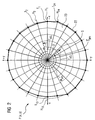
- FIG. 2 shows a Cartesian coordinate system P ( x, y ) with an outlet temperature distribution at a time t 0 .
- each auxiliary straight line H i based on the positive x-axis an angle ⁇ i, whose value is 15 ° or an integer multiple thereof.
- Detected for each of the temperature measuring devices M i T i temperature is entered on its associated auxiliary axis H i is a point whose distance from the origin P is proportional to (0.0) of the temperature T i to the detected amount.
- auxiliary axis H i 1..n, a point dependent on the local temperature T i results.
- T x i T i ⁇ cos ( ⁇ i )
- i 1..24
- T y i T i * Sin ( ⁇ i )
- i 1..24 a projection on the two axes of the coordinate system.
- the temperature measuring devices M i are all disposed lying in a plane which extends perpendicular to the axis of rotation 2 and thus simultaneously to the main flow direction of the exhaust gas. Another uneven distribution of the temperature measuring devices M i over the circumference would also be feasible with the method.
- equations (5) and (6) in equation (3) and equations (7) and (8) in equation (4) are used and transformed so that the reference value of the x-axis is and that of the y-axis
- the origin of the gravity vector, S ges lies in the coordinate origin P (0, 0) and ends in the center of gravity S, which lies at the point P (T xGL , T yGL ).
- the angle ⁇ ges is related to the positive x-axis in the mathematically positive sense, wherein the usual considerations for the size of the angle ⁇ ges are applied in the application of the tangent function.
- the points of the temperatures T i recorded on the auxiliary axes H i are connected to each other via a circumferential line 22, so that they together form a polygonal, almost circular area 23 whose center of gravity S is determined by application of the method.
- FIG. 3 shows the time profile of the center of gravity vector S ges shown in a combined amount-time and angle-time diagram.
- the focus vector S ges is determined by the amount S ges and the angle ⁇ ges , wherein the angle ⁇ ges in a dashed line type and the amount S ges is shown as a solid line.
- the angle ⁇ ges changes significantly and decreases approximately to half of its previous value.
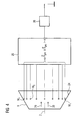
- the apparatus for monitoring the center of gravity vector is shown S ges shown. It has an evaluation device 25, which applies the method.
- the evaluation device 25 is connected to all temperature measuring devices M i and to a display device 26. From the detected temperatures T i , the evaluation device 25 calculates the center of gravity vector S sat and check if its amount S ges or whose angle ⁇ ges is outside a tolerance interval. If this is the case, the evaluation device 25 generates a signal for the display device 26, which then displays a fault as the operating state.
- the display device 26 may be a monitor or a control lamp.
Landscapes
- Engineering & Computer Science (AREA)
- Physics & Mathematics (AREA)
- General Physics & Mathematics (AREA)
- Mechanical Engineering (AREA)
- General Engineering & Computer Science (AREA)
- Control Of Turbines (AREA)
- Testing Of Devices, Machine Parts, Or Other Structures Thereof (AREA)
- Measuring Temperature Or Quantity Of Heat (AREA)
Priority Applications (7)
| Application Number | Priority Date | Filing Date | Title |
|---|---|---|---|
| EP03019868A EP1510656A1 (fr) | 2003-09-01 | 2003-09-01 | Procédé et système pour déterminer le mode opératoire d'une turbine à gaz |
| CN2004800234850A CN1836092B (zh) | 2003-09-01 | 2004-07-23 | 检测涡轮机工作状态的方法 |
| PCT/EP2004/008290 WO2005028814A1 (fr) | 2003-09-01 | 2004-07-23 | Procede et dispositif permettant la detection de l'etat de fonctionnement d'une turbine |
| EP04763460A EP1660759B1 (fr) | 2003-09-01 | 2004-07-23 | Procede pour determiner le mode operatoire d'une turbine a gaz |
| ES04763460T ES2302018T3 (es) | 2003-09-01 | 2004-07-23 | Procedimiento para reconocer un estado de funcionamiento de una turbina. |
| DE502004006601T DE502004006601D1 (de) | 2003-09-01 | 2004-07-23 | Er turbine |
| US10/570,514 US7899647B2 (en) | 2003-09-01 | 2004-07-23 | Method and device for identifying the operating condition of a turbine |
Applications Claiming Priority (1)
| Application Number | Priority Date | Filing Date | Title |
|---|---|---|---|
| EP03019868A EP1510656A1 (fr) | 2003-09-01 | 2003-09-01 | Procédé et système pour déterminer le mode opératoire d'une turbine à gaz |
Publications (1)
| Publication Number | Publication Date |
|---|---|
| EP1510656A1 true EP1510656A1 (fr) | 2005-03-02 |
Family
ID=34089657
Family Applications (2)
| Application Number | Title | Priority Date | Filing Date |
|---|---|---|---|
| EP03019868A Withdrawn EP1510656A1 (fr) | 2003-09-01 | 2003-09-01 | Procédé et système pour déterminer le mode opératoire d'une turbine à gaz |
| EP04763460A Expired - Lifetime EP1660759B1 (fr) | 2003-09-01 | 2004-07-23 | Procede pour determiner le mode operatoire d'une turbine a gaz |
Family Applications After (1)
| Application Number | Title | Priority Date | Filing Date |
|---|---|---|---|
| EP04763460A Expired - Lifetime EP1660759B1 (fr) | 2003-09-01 | 2004-07-23 | Procede pour determiner le mode operatoire d'une turbine a gaz |
Country Status (6)
| Country | Link |
|---|---|
| US (1) | US7899647B2 (fr) |
| EP (2) | EP1510656A1 (fr) |
| CN (1) | CN1836092B (fr) |
| DE (1) | DE502004006601D1 (fr) |
| ES (1) | ES2302018T3 (fr) |
| WO (1) | WO2005028814A1 (fr) |
Cited By (4)
| Publication number | Priority date | Publication date | Assignee | Title |
|---|---|---|---|---|
| DE102006019578A1 (de) * | 2006-04-27 | 2007-10-31 | Abb Patent Gmbh | Vorrichtung zur Messung der Gas oder Lufttemperatur in einem Gehäuse |
| WO2011039153A1 (fr) * | 2009-09-29 | 2011-04-07 | Siemens Aktiengesellschaft | Dispositif produisant des gaz d'échappement, notamment bateau, comportant un système de détermination du volume de gaz d'échappement |
| EP1777394A3 (fr) * | 2005-10-24 | 2012-06-20 | General Electric Company | Contrôle de la formation de trainées chaudes dans une chambre de combustion de turbine à gaz |
| WO2019052734A1 (fr) * | 2017-09-14 | 2019-03-21 | Siemens Aktiengesellschaft | Procédé pour repérer une mauvaise position angulaire d'une aube directrice de compresseur agencée dans un compresseur et pouvant pivoter autour de son axe longitudinal |
Families Citing this family (9)
| Publication number | Priority date | Publication date | Assignee | Title |
|---|---|---|---|---|
| EP3199781B1 (fr) * | 2016-01-27 | 2019-05-01 | Ansaldo Energia IP UK Limited | Turbine à gaz et procédé correspondant pour commander un fonctionnement d'une turbine à gaz avec des capteurs de température de sortie de turbine sélectionnés |
| DE102017101161A1 (de) * | 2017-01-23 | 2018-07-26 | Man Diesel & Turbo Se | Gasturbine |
| IT201700028071A1 (it) * | 2017-03-14 | 2018-09-14 | Nuovo Pignone Tecnologie Srl | Metodi per rilevare un guasto in un bruciatore di un combustore e sistemi a turbina |
| EP3531019A1 (fr) * | 2018-02-27 | 2019-08-28 | Siemens Aktiengesellschaft | Procédé d'analyse pour une turbine à gaz |
| RU2696919C1 (ru) * | 2018-04-18 | 2019-08-07 | Акционерное общество "РОТЕК" (АО "РОТЕК") | Способ и система оценки технического состояния узлов газовой турбины по температурным полям |
| US11352077B2 (en) * | 2018-12-31 | 2022-06-07 | Contitech Transportbandsysteme Gmbh | Tethered temperature sensor for use in rubber embedded applications |
| CN112903301B (zh) * | 2019-12-04 | 2023-09-15 | 西门子能源国际公司 | 识别燃气轮机运行状态的方法和装置 |
| JP7657670B2 (ja) * | 2021-07-05 | 2025-04-07 | 東芝エネルギーシステムズ株式会社 | 損傷評価装置、損傷評価方法 |
| CN117391160A (zh) * | 2022-07-01 | 2024-01-12 | 阿里巴巴(中国)有限公司 | 加速方法、加速器和存储介质 |
Citations (6)
| Publication number | Priority date | Publication date | Assignee | Title |
|---|---|---|---|---|
| GB989011A (en) * | 1961-02-16 | 1965-04-14 | Bbc Brown Boveri & Cie | Apparatus for controlling the operation of a machine |
| JPH0264232A (ja) * | 1988-08-30 | 1990-03-05 | Hitachi Ltd | ガスタービン燃焼器の監視表示装置 |
| US5878566A (en) * | 1994-12-05 | 1999-03-09 | Hitachi, Ltd. | Gas turbine and a gas turbine control method |
| DE19821956A1 (de) * | 1998-05-16 | 1999-11-18 | Deutsch Zentr Luft & Raumfahrt | Verfahren zur quantitativen Analyse von Gasvolumina, insbesondere von Abgasen aus Verbrennungseinrichtungen oder -anlagen, sowie Einrichtungen zur Durchführung des Verfahrens |
| EP1118920A1 (fr) * | 2000-01-20 | 2001-07-25 | General Electric Company | Système de protection d'une machine pour équipements rotatifs et procédé |
| US20020183916A1 (en) * | 2000-08-30 | 2002-12-05 | General Electric Company. | Method and system for identifying malfunctioning combustion chambers in a gas turbine |
Family Cites Families (6)
| Publication number | Priority date | Publication date | Assignee | Title |
|---|---|---|---|---|
| US4735052A (en) * | 1985-09-30 | 1988-04-05 | Kabushiki Kaisha Toshiba | Gas turbine apparatus |
| JPH01114623A (ja) * | 1987-10-27 | 1989-05-08 | Toshiba Corp | ガスタービン燃焼器 |
| SG104914A1 (en) * | 1997-06-30 | 2004-07-30 | Hitachi Ltd | Gas turbine |
| DE50115614D1 (de) * | 2001-04-17 | 2010-10-14 | Alstom Technology Ltd | Verfahren zur Unterdrückung von Verbrennungsfluktuationen in einer Gasturbine |
| US7416137B2 (en) * | 2003-01-22 | 2008-08-26 | Vast Power Systems, Inc. | Thermodynamic cycles using thermal diluent |
| US7269939B2 (en) * | 2004-11-24 | 2007-09-18 | General Electric Company | Method and apparatus for automatically actuating fuel trim valves in a gas |
-
2003
- 2003-09-01 EP EP03019868A patent/EP1510656A1/fr not_active Withdrawn
-
2004
- 2004-07-23 ES ES04763460T patent/ES2302018T3/es not_active Expired - Lifetime
- 2004-07-23 DE DE502004006601T patent/DE502004006601D1/de not_active Expired - Lifetime
- 2004-07-23 US US10/570,514 patent/US7899647B2/en not_active Expired - Fee Related
- 2004-07-23 CN CN2004800234850A patent/CN1836092B/zh not_active Expired - Fee Related
- 2004-07-23 EP EP04763460A patent/EP1660759B1/fr not_active Expired - Lifetime
- 2004-07-23 WO PCT/EP2004/008290 patent/WO2005028814A1/fr not_active Ceased
Patent Citations (6)
| Publication number | Priority date | Publication date | Assignee | Title |
|---|---|---|---|---|
| GB989011A (en) * | 1961-02-16 | 1965-04-14 | Bbc Brown Boveri & Cie | Apparatus for controlling the operation of a machine |
| JPH0264232A (ja) * | 1988-08-30 | 1990-03-05 | Hitachi Ltd | ガスタービン燃焼器の監視表示装置 |
| US5878566A (en) * | 1994-12-05 | 1999-03-09 | Hitachi, Ltd. | Gas turbine and a gas turbine control method |
| DE19821956A1 (de) * | 1998-05-16 | 1999-11-18 | Deutsch Zentr Luft & Raumfahrt | Verfahren zur quantitativen Analyse von Gasvolumina, insbesondere von Abgasen aus Verbrennungseinrichtungen oder -anlagen, sowie Einrichtungen zur Durchführung des Verfahrens |
| EP1118920A1 (fr) * | 2000-01-20 | 2001-07-25 | General Electric Company | Système de protection d'une machine pour équipements rotatifs et procédé |
| US20020183916A1 (en) * | 2000-08-30 | 2002-12-05 | General Electric Company. | Method and system for identifying malfunctioning combustion chambers in a gas turbine |
Non-Patent Citations (1)
| Title |
|---|
| PATENT ABSTRACTS OF JAPAN vol. 014, no. 237 (M - 0976) 21 May 1990 (1990-05-21) * |
Cited By (6)
| Publication number | Priority date | Publication date | Assignee | Title |
|---|---|---|---|---|
| EP1777394A3 (fr) * | 2005-10-24 | 2012-06-20 | General Electric Company | Contrôle de la formation de trainées chaudes dans une chambre de combustion de turbine à gaz |
| DE102006019578A1 (de) * | 2006-04-27 | 2007-10-31 | Abb Patent Gmbh | Vorrichtung zur Messung der Gas oder Lufttemperatur in einem Gehäuse |
| US8262285B2 (en) | 2006-04-27 | 2012-09-11 | Abb Ag | Device for measuring gas or air temperature in a casing box |
| WO2011039153A1 (fr) * | 2009-09-29 | 2011-04-07 | Siemens Aktiengesellschaft | Dispositif produisant des gaz d'échappement, notamment bateau, comportant un système de détermination du volume de gaz d'échappement |
| US9157780B2 (en) | 2009-09-29 | 2015-10-13 | Siemens Aktiengesellschaft | Device generating exhaust gas, especially a boat, comprising a system for determining the volume of exhaust gas |
| WO2019052734A1 (fr) * | 2017-09-14 | 2019-03-21 | Siemens Aktiengesellschaft | Procédé pour repérer une mauvaise position angulaire d'une aube directrice de compresseur agencée dans un compresseur et pouvant pivoter autour de son axe longitudinal |
Also Published As
| Publication number | Publication date |
|---|---|
| US20060245914A1 (en) | 2006-11-02 |
| CN1836092A (zh) | 2006-09-20 |
| ES2302018T3 (es) | 2008-07-01 |
| EP1660759A1 (fr) | 2006-05-31 |
| WO2005028814A1 (fr) | 2005-03-31 |
| EP1660759B1 (fr) | 2008-03-19 |
| CN1836092B (zh) | 2010-08-11 |
| US7899647B2 (en) | 2011-03-01 |
| DE502004006601D1 (de) | 2008-04-30 |
Similar Documents
| Publication | Publication Date | Title |
|---|---|---|
| EP1510656A1 (fr) | Procédé et système pour déterminer le mode opératoire d'une turbine à gaz | |
| EP1454058B1 (fr) | Procede pour surveiller un detecteur | |
| DE102008002911B4 (de) | Systeme und Verfahren für die Anwendung eines Verbrennungsdynamik-Abstimmalgorithmus bei einer Mehrbrennkammerrohr-Brennkammer | |
| DE102010016615A1 (de) | Fehlererkennung und Schutz von mehrstufigen Verdichtern | |
| EP0555294B1 (fr) | Controle du fonctionnement d'un condenseur pourvu de tubes par des mesures effectuees sur des tubes selectionnes | |
| DE4422701B4 (de) | Gasturbogruppe mit sequentieller Verbrennung | |
| DE102011056567B4 (de) | Anlage mit einem System zum Erkennen von Abplatzen in einer Turbine | |
| DE60207364T2 (de) | Einrichtung und Methode zur Entdeckung einer beschädigten Rotorschaufel | |
| DE102008002865A1 (de) | Verfahren und System zur Messung der Schaufelverformung in Turbinen | |
| DE112014001000T5 (de) | Gasturbinensystem, Steuer- bzw. Regelungseinrichtung und Gasturbinenbetriebsverfahren | |
| DE102011057163A1 (de) | System zur Zuführung einer Kühl- und Spülluftströmung zu einem Online-Überwachungssystem einer Rotationsmaschine | |
| EP1994371A1 (fr) | Dispositif de mesure d'écoulement pour déterminer un sens d'écoulement | |
| CH704827B1 (de) | Abgasnutzturbine, Abwärmerückgewinnungssystem und Verfahren zum Betreiben eines Abwärmerückgewinnungssystems. | |
| DE102015226732A1 (de) | Sensoranordnung und Messverfahren für eine Turbomaschine | |
| WO1996020395A1 (fr) | Procede et dispositif permettant de determiner une puissance | |
| DE102006031551B4 (de) | Flammenrückschlag-Erfassungseinrichtung, Flammenrückschlag-Erfassungsverfahren und Gasturbine | |
| CH703593A2 (de) | System und Verfahren für den Betrieb einer Gasturbine. | |
| WO2009056489A2 (fr) | Procédé de détermination de la durée de vie restante d'un rotor d'une turbomachine subissant une contrainte thermique | |
| WO2007104614A1 (fr) | Dispositif de mesure d'écoulement pour déterminer un sens d'écoulement | |
| DE112020004156T5 (de) | Anomalieerfassungsvorrichtung und Anzeigevorrichtung | |
| DE19651073A1 (de) | Verfahren zur Ermittlung von Lecks im geschlossenen oder halboffenen Kühlsystem einer Gasturbine | |
| DE69002194T2 (de) | Durchflussmesser. | |
| EP1518039B1 (fr) | Procede de fonctionnement d'une installation de turbines a gaz et installation de turbines a gaz | |
| DE102017216279A1 (de) | Verfahren zur Erkennung einer Fehlstellung der Winkellage einer in einem Verdichter angeordneten, um ihre Längsachse schwenkbaren Verdichterleitschaufel | |
| EP1580537A1 (fr) | Procédé et dispositif de détection d'erreurs du système d'air de refroidissement d'une turbine |
Legal Events
| Date | Code | Title | Description |
|---|---|---|---|
| PUAI | Public reference made under article 153(3) epc to a published international application that has entered the european phase |
Free format text: ORIGINAL CODE: 0009012 |
|
| AK | Designated contracting states |
Kind code of ref document: A1 Designated state(s): AT BE BG CH CY CZ DE DK EE ES FI FR GB GR HU IE IT LI LU MC NL PT RO SE SI SK TR |
|
| AX | Request for extension of the european patent |
Extension state: AL LT LV MK |
|
| AKX | Designation fees paid | ||
| REG | Reference to a national code |
Ref country code: DE Ref legal event code: 8566 |
|
| STAA | Information on the status of an ep patent application or granted ep patent |
Free format text: STATUS: THE APPLICATION IS DEEMED TO BE WITHDRAWN |
|
| 18D | Application deemed to be withdrawn |
Effective date: 20050903 |