EP1510814A1 - Detecteur de gaz, systeme de pile a combustible l'utilisant et automobile - Google Patents
Detecteur de gaz, systeme de pile a combustible l'utilisant et automobile Download PDFInfo
- Publication number
- EP1510814A1 EP1510814A1 EP04733655A EP04733655A EP1510814A1 EP 1510814 A1 EP1510814 A1 EP 1510814A1 EP 04733655 A EP04733655 A EP 04733655A EP 04733655 A EP04733655 A EP 04733655A EP 1510814 A1 EP1510814 A1 EP 1510814A1
- Authority
- EP
- European Patent Office
- Prior art keywords
- output
- value
- gas sensor
- heater element
- gas
- Prior art date
- Legal status (The legal status is an assumption and is not a legal conclusion. Google has not performed a legal analysis and makes no representation as to the accuracy of the status listed.)
- Withdrawn
Links
Images







Classifications
-
- H—ELECTRICITY
- H01—ELECTRIC ELEMENTS
- H01M—PROCESSES OR MEANS, e.g. BATTERIES, FOR THE DIRECT CONVERSION OF CHEMICAL ENERGY INTO ELECTRICAL ENERGY
- H01M8/00—Fuel cells; Manufacture thereof
- H01M8/04—Auxiliary arrangements, e.g. for control of pressure or for circulation of fluids
- H01M8/04082—Arrangements for control of reactant parameters, e.g. pressure or concentration
- H01M8/04089—Arrangements for control of reactant parameters, e.g. pressure or concentration of gaseous reactants
-
- G—PHYSICS
- G01—MEASURING; TESTING
- G01N—INVESTIGATING OR ANALYSING MATERIALS BY DETERMINING THEIR CHEMICAL OR PHYSICAL PROPERTIES
- G01N27/00—Investigating or analysing materials by the use of electric, electrochemical, or magnetic means
- G01N27/02—Investigating or analysing materials by the use of electric, electrochemical, or magnetic means by investigating impedance
- G01N27/04—Investigating or analysing materials by the use of electric, electrochemical, or magnetic means by investigating impedance by investigating resistance
- G01N27/14—Investigating or analysing materials by the use of electric, electrochemical, or magnetic means by investigating impedance by investigating resistance of an electrically-heated body in dependence upon change of temperature
- G01N27/18—Investigating or analysing materials by the use of electric, electrochemical, or magnetic means by investigating impedance by investigating resistance of an electrically-heated body in dependence upon change of temperature caused by changes in the thermal conductivity of a surrounding material to be tested
-
- H—ELECTRICITY
- H01—ELECTRIC ELEMENTS
- H01M—PROCESSES OR MEANS, e.g. BATTERIES, FOR THE DIRECT CONVERSION OF CHEMICAL ENERGY INTO ELECTRICAL ENERGY
- H01M8/00—Fuel cells; Manufacture thereof
- H01M8/04—Auxiliary arrangements, e.g. for control of pressure or for circulation of fluids
- H01M8/04223—Auxiliary arrangements, e.g. for control of pressure or for circulation of fluids during start-up or shut-down; Depolarisation or activation, e.g. purging; Means for short-circuiting defective fuel cells
- H01M8/04228—Auxiliary arrangements, e.g. for control of pressure or for circulation of fluids during start-up or shut-down; Depolarisation or activation, e.g. purging; Means for short-circuiting defective fuel cells during shut-down
-
- H—ELECTRICITY
- H01—ELECTRIC ELEMENTS
- H01M—PROCESSES OR MEANS, e.g. BATTERIES, FOR THE DIRECT CONVERSION OF CHEMICAL ENERGY INTO ELECTRICAL ENERGY
- H01M8/00—Fuel cells; Manufacture thereof
- H01M8/04—Auxiliary arrangements, e.g. for control of pressure or for circulation of fluids
- H01M8/04298—Processes for controlling fuel cells or fuel cell systems
- H01M8/04313—Processes for controlling fuel cells or fuel cell systems characterised by the detection or assessment of variables; characterised by the detection or assessment of failure or abnormal function
- H01M8/0444—Concentration; Density
-
- H—ELECTRICITY
- H01—ELECTRIC ELEMENTS
- H01M—PROCESSES OR MEANS, e.g. BATTERIES, FOR THE DIRECT CONVERSION OF CHEMICAL ENERGY INTO ELECTRICAL ENERGY
- H01M8/00—Fuel cells; Manufacture thereof
- H01M8/04—Auxiliary arrangements, e.g. for control of pressure or for circulation of fluids
- H01M8/04298—Processes for controlling fuel cells or fuel cell systems
- H01M8/04694—Processes for controlling fuel cells or fuel cell systems characterised by variables to be controlled
- H01M8/04746—Pressure; Flow
- H01M8/04753—Pressure; Flow of fuel cell reactants
-
- H—ELECTRICITY
- H01—ELECTRIC ELEMENTS
- H01M—PROCESSES OR MEANS, e.g. BATTERIES, FOR THE DIRECT CONVERSION OF CHEMICAL ENERGY INTO ELECTRICAL ENERGY
- H01M2250/00—Fuel cells for particular applications; Specific features of fuel cell system
- H01M2250/20—Fuel cells in motive systems, e.g. vehicle, ship, plane
-
- Y—GENERAL TAGGING OF NEW TECHNOLOGICAL DEVELOPMENTS; GENERAL TAGGING OF CROSS-SECTIONAL TECHNOLOGIES SPANNING OVER SEVERAL SECTIONS OF THE IPC; TECHNICAL SUBJECTS COVERED BY FORMER USPC CROSS-REFERENCE ART COLLECTIONS [XRACs] AND DIGESTS
- Y02—TECHNOLOGIES OR APPLICATIONS FOR MITIGATION OR ADAPTATION AGAINST CLIMATE CHANGE
- Y02E—REDUCTION OF GREENHOUSE GAS [GHG] EMISSIONS, RELATED TO ENERGY GENERATION, TRANSMISSION OR DISTRIBUTION
- Y02E60/00—Enabling technologies; Technologies with a potential or indirect contribution to GHG emissions mitigation
- Y02E60/30—Hydrogen technology
- Y02E60/50—Fuel cells
-
- Y—GENERAL TAGGING OF NEW TECHNOLOGICAL DEVELOPMENTS; GENERAL TAGGING OF CROSS-SECTIONAL TECHNOLOGIES SPANNING OVER SEVERAL SECTIONS OF THE IPC; TECHNICAL SUBJECTS COVERED BY FORMER USPC CROSS-REFERENCE ART COLLECTIONS [XRACs] AND DIGESTS
- Y02—TECHNOLOGIES OR APPLICATIONS FOR MITIGATION OR ADAPTATION AGAINST CLIMATE CHANGE
- Y02T—CLIMATE CHANGE MITIGATION TECHNOLOGIES RELATED TO TRANSPORTATION
- Y02T90/00—Enabling technologies or technologies with a potential or indirect contribution to GHG emissions mitigation
- Y02T90/40—Application of hydrogen technology to transportation, e.g. using fuel cells
Definitions
- the present invention relates to a gas sensor for sensing the concentration of a gas to be sensed and humidity, mixed in atmospheric air containing moisture.
- the present invention also relates to a fuel cell system using the gas sensor, and to an automobile using the system.
- Fuel cells expected as a bargaining chip to solve energy and environmental issues, have been positively developed in recent years. Especially, a fuel cell with a solid polymer film used as its electrolyte is easy to handle owing to its low operating temperature of approximately 80°C, and thus is currently a mainstream in development of fuel cells.
- a gas sensor for sensing hydrogen is required as a safety measure against leakage.
- a conventional gas sensor senses the change in heat conductivity due to the presence of hydrogen, as the change in temperature of a heater element, using a property of hydrogen that is its heat conductivity is extremely high compared to other gases. For example, if hydrogen exists in the air, more heat is lost from the heater element than in a case where hydrogen does not exist. Consequently, the temperature of the heater element changes according to the hydrogen concentration.
- the conventional gas sensor electrically senses this temperature change as the change in resistance value of the temperature-sensing element.
- the gas sensor uses a platinum thin-film resistive element for the heater element (also used for a temperature-sensing element).
- This element a thin-film, can be manufactured using semiconductor fine processing technology (i.e. micromachining), enabling a submicroscopic heater element to be formed. Accordingly, the response speed of the gas sensor is enhanced with lower power consumption.
- semiconductor fine processing technology i.e. micromachining
- the conventional gas sensor changes the current passing through the heater element. This changes the output voltage across the heater element according to the degree of response. Then, the voltages across the heater element when different amounts of current are passed are substituted into an estimation equation obtained in advance, and then simultaneous equations are produced. Accordingly, the amount of each gas, namely the concentration of each gas is obtained from the solutions to the estimation equations.
- such a solving method allows the gas concentrations of a plurality of components to be obtained.
- a problem exists where, at approximately 80° C, in such as sensing leakage from a fuel cell, hydrogen almost saturated with vapor leaks into the atmospheric air.
- hydrogen concentration and humidity can be obtained using Chebyshev orthogonal polynomial.
- a large amount of vapor is assumed to exist as compared to hydrogen.
- Such a case shows a nonlinear (always having an order of two or more) characteristic.
- a gas sensor includes a heater element that contacts a gas to be sensed, mixed in the atmospheric air containing moisture; a power supply unit for supplying the heater element with a current; and a voltmeter for measuring a voltage across the heater element.
- the gas sensor further includes a calculator for calculating and outputting the humidity and concentration of a gas to be sensed from an output voltage of the voltmeter.
- the calculator supplies the heater element with at least three levels of current, stepwise and continuously for a predetermined time, using the power supply unit. Then, the calculator loads voltages across the heater element after a predetermined elapsed time for the respective current values, and calculates a temperature from the voltage across the heater element for the minimum amount of current.
- the calculator From the temperature, and from a zero-point correcting formula and a sensitivity-correcting formula, obtained in advance with concentration-known gases to be sensed, the calculator corrects the voltages across the heater element for other than the above-mentioned minimum current to obtain respective normalized outputs. From the difference in these normalized outputs, the calculator calculates humidity, and corrects the normalized outputs with the humidity and a humidity-correcting formula obtained in advance with concentration-known gases to be sensed, to obtain the concentration of the gas to be sensed. In such a way, the gas sensor according to the present invention outputs humidity and the concentration of a gas to be sensed well accurately.
- Fig. 1 is an exploded perspective view of a gas sensing part of a gas sensor of an embodiment according to the present invention.
- Fig. 2 is a schematic perspective view of a heater element of the gas sensor.
- Fig. 3 is a schematic sectional view of a part shown by the alternate long and short dashed line in Fig. 2.
- Fig. 4 shows an enlarged cross section of the winding part of heater element 1, shown by the area surround a broken line in Fig. 3.
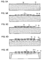
- Figs. 5A through 5E are schematic diagrams of an outline manufacturing process of the heater element.
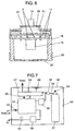
- Fig. 6 is a schematic sectional view of the gas sensor.
- Heater element 1 fixed on base 2, contacts a gas to be sensed and mixed in atmospheric air containing moisture.
- Two pins 3 are provided so as to pierce base 2, and each of two pairs of wires 4, made of gold, connects a top surface of each of pins 3 to heater element 1.
- Using a pair of wires 4 allows the gas sensor to be used continuously, improving reliability because one wire 4 remains connected even if another breaks.
- Base 2 has a double-canned makeup. That is, base 2 is capped with inner can 6 having four inner holes 5, and thereon further capped with outer can 8 having one outer hole 7. Inner holes 5 and outer hole 7 are displaced from each other when they are capped on base 2, not facing each other.
- inner can 6, and outer can 8 are all fixed each other with resistance welding.
- net 9 made of metal such as stainless-steel is fixed. Providing net 9 prevents flames from being propagated out of net 9, because the net absorbs the heat even if a gas to be sensed such as hydrogen burns inside the gas sensor. Net 9 works as long as it is provided on either inner holes 5 or outer hole 7.
- inner can 6, outer can 8, and net 9 are colored with black chromium plating.
- Such a manner allows cans 6 and 8, and net 9 to absorb radiation heat from heater element 1 and the outside, reducing the impact on the heating temperature of heater element 1, due to diffuse reflection on cans 6 and 8, and net 9. This works as long as any one of inner can 6, outer can 8, and net 9 is black-colored.
- Heater element 1 includes pedestal 10, made of silicon; and heat generator 11, made of a platinum thin-film formed on pedestal 10 in a winding form with micromachining. Pedestal 10 is also processed in a winding form according to the shape of heat generator 11. In other words, winding part 30 is provided with heat generator 11. At both ends of heat generator 11, land 12 is provided for bonding wires 4. Still as shown in Fig. 4, heat generator 11 and land 12 are formed on insulating layer 14 made of silica. Also on the top surface of heat generator 11, protective layer 15 made of silica is formed. In this way, insulating layer 14, heat generator 11, and protective layer 15 make a laminated structure.
- Forming protective layer 15 prevents an impure substance included in a gas to be sensed from directly adhering to the surface of heater element 1, improving the reliability of heater element 1.
- insulating layer 14 and protective layer 15 are made of silica, they contact pedestal 10 made of silicon well firmly. This prevents an impure substance included in a gas to be sensed from directly adhering to the surface of heater element 1, improving the reliability of heater element 1.
- making heat generator 11 with a platinum thin-film allows the wiring pattern of heater element 1 and heat generator 11 to be formed integrally, simplifying their manufacture process.
- heater element 1 with winding part 30 has a large surface area, improving the sensitivity of the gas sensor accordingly.
- dent 13 is formed under insulating layer 14, which is a dented part of the lower surface of pedestal 10 in Fig. 3, where heat generator 11 is provided.
- the heat capacity of heater element 1 is reduced, the gas sensor can respond in a high-speed, and is reduced in power consumption.
- winding part 30, where dent 13 is provided is made thin with a thickness of at least 3 micrometers but at most 10 micrometers, the heat capacity becomes extremely low, with the strength of heater element 1 being secured, reducing the time for temperature stabilization to the order of sub-second.
- through-hole 31 is provided at winding part 30, namely a part of heater element 1, through-hole 31 is provided. Through-hole 31 reduces the amount of heat transferring from heat generator 11 to pedestal 10, to reduce the time for stabilization of the element temperature, resulting in heater element 1 with an excellent reproducibility for repeated heating.
- insulating layer 14 made of silica on the whole surface of pedestal 10 with sputtering.
- Fig. 5B sputter platinum using a mask pattern exposed in a winding form, on the top surface of insulating layer 14 to form heat generator 11.
- Fig. 5C form protective layer 15 made of silica with sputtering using a mask pattern exposed only at a part corresponding to heat generator 11. This causes protective layer 15 to be formed only on the top surface of heat generator 11.
- Fig. 5D deeply etch the silicon surrounding heat generator 11 using a winding-shaped pattern.
- Fig. 5D deeply etch the silicon surrounding heat generator 11 using a winding-shaped pattern.
- Heater element 1 produced in such a way is packaged in a case composed of base 2, inner can 6, and outer can 8, shown in Fig. 1 to form sensing part 16.
- Sensing part 16 is connected to sensing circuit 17 electrically and mechanically, with pin 3 inserted into sensing circuit 17 and soldered as shown in Fig. 6.
- Sensing circuit 17 is inserted in container 18, and container lid 20 is inlaid with extraction cable 19 connected to sensing circuit 17, laced in advance.
- Moisture-resistant resin 21 is injected into the whole space which exists from the inlet (not illustrated) provided on container lid 20 and between sensing circuit 17 and container lid 20, and hardened.
- Container 18 and container lid 20 are crimped to each other after moisture-resistant resin 21 is injected and hardened.
- Gas inlets 22 are provided on the bottom surface of container 18, and screw part 23 is processed for mounting a sensor on the side. In this way, gas sensor 24 completes.
- FIG. 7 is a schematic block diagram of a stationary fuel cell system on which the gas sensor of the embodiment according to the present invention installed.
- Fig. 8 is a sectional view showing an outline structure of an automobile equipped with the fuel cell using the gas sensor of the embodiment according to the present invention.
- Fuel cell 54 generates electric power using hydrogen as a fuel.
- Hydrogen tank 51 is replaced with a reformer for a reforming-type fuel cell system.
- the hydrogen in hydrogen tank 51 is introduced to hydrogen humidifier 53 through isolation valve 52.
- Hydrogen is given moisture here to prevent the solid polymer film in the fuel cell from being dried.
- the humidified hydrogen is introduced to the hydrogen electrode of fuel cell 54.
- air required to generate power, humidified with air humidifier 56 is introduced to the air electrode of fuel cell 54 with compressor 55.
- fuel cell 54 generates power and supply an external device with the power through control circuit 57 as shown by the heavy lines.
- the water resulting from the power generation is discharged to the outside with air from fuel cell 54.
- gas sensors 24 for sensing hydrogen leakage are arranged near hydrogen tank 51, near fuel cell 54, at a part of the outlet piping for the air electrode of fuel cell 54, and at others. If any of gas sensors 24 senses hydrogen leakage, and its output exceeds a predetermined value, control circuit 57 closes isolation valve 52 to stop supplying fuel cell 54 with hydrogen. Then, alarm unit 59, which is an annunciator, and ventilation fan 60 are activated for ventilating space 62 including fuel cell 54 and duct 61 for hydrogen.
- Gas sensor 24, with the aforementioned makeup is capable of sensing hydrogen concentration well accurately even in a gas to be sensed including moisture. Therefore, a fuel cell system with gas sensor 24 provides a high level of safety against hydrogen leakage. Still, instead of alarm unit 59, the annunciator may be composed of an indicator such as a red lamp.
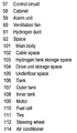
- Main body 101 of the automobile is formed with cabin space 102, hydrogen tank storage space 103, drive unit storage space 104, and underfloor space 105, each separately.
- Space 103 is equipped with tank 106 for storing hydrogen.
- Tank 106 is double-structured with outer tank 107 and inner tank 108, in order to secure safety especially against hydrogen leakage at the time of a crash, where inner tank 108 stores hydrogen therein.
- Drive unit storage space 104 is equipped with motor 109 for driving tire 111 supporting main body 101.
- Underfloor space 105 is equipped with fuel cell 54.
- fuel cell 54 provided in underfloor space 105 Using hydrogen supplied from tank 106 as a fuel, fuel cell 54 provided in underfloor space 105 generates power, and the power is supplied to motor 109 to drive tire 111.
- the steering direction for tire 111 is controlled with steering wheel 112 in cabin space 102.
- gas sensor 24 in cabin space 102 is provided at the front part of the ceiling, which is the highest part in cabin space 102.
- Gas sensor 24 in hydrogen tank storage space 103 is provided at the top of outer tank 107 because tank 106 is double-structured.
- Gas sensor 113 in drive unit storage space 104 is provided at the rear end of the hood (bonnet), which is the highest part in drive unit storage space 104.
- Gas sensor 113 provided in underfloor space 105 is arranged at the highest part of underfloor space 104. Further, although not illustrated, similarly to Fig. 7, the gas sensor is also arranged at a part of the outlet piping for the air electrode of fuel cell 54.
- control circuit 57 blocks the hydrogen supply source to stop supplying fuel cell 54 with hydrogen.
- alarm unit 59 which is an annunciator, alarms.
- ventilation fan 60 ventilates the space provided in main body 101. Still in Fig. 8, although ventilation fan 60 is provided only in space 104, similar fan(s) to ventilation fan 60 may be provided in other spaces.
- gas sensor 24 provided in cabin space 102 also senses moisture, and is usually used to control air conditioner 114 equipped at a part of cabin space 102 to keep optimum the humidity in cabin space 102.
- gas sensor 24 enables not only sensing hydrogen leakage, but obtaining humidity data. Consequently, gas sensor 24 usually controls the air conditioner, and when hydrogen leaks, it controls to ventilate and to block the hydrogen supply source, improving both safety and comfort of the automobile simultaneously.
- gas sensors 24 are always operating. If any one of gas sensors 24 senses hydrogen leakage, ventilation fan 60 automatically ventilates to prevent hydrogen from pervading. In this case, heater element 1, with its very small size, needs very little electricity to work. Therefore, gas sensor 24 can be satisfactorily driven even while the automobile is not being used, and hydrogen leakage can be sensed even so, further improving safety.
- Fig. 9 is an outline circuit diagram for illustrating the circuitry of a gas sensor according to the embodiment of the present invention.
- Heater element 1 is connected to constant current source 25 as a power supply unit, and also connected to voltmeter 26 for measuring a voltage across heater element 1, in parallel with constant current source 25.
- Constant current source 25 and voltmeter 26 are further connected to calculator 27 including a microprocessor.
- Calculator 27 controls constant current source 25, and also performs a predetermined calculation using the output from voltmeter 26 to output data of hydrogen concentration and humidity.
- Constant current source 25, voltmeter 26, and calculator 27 are included in sensing circuit 16 in Fig. 6.
- Fig. 10 is an outline waveform chart for the currents applied to heater element 1 of gas sensor 24.
- Constant current source 25 supplies heater element 1 with three levels of current, stepwise and continuously for a predetermined time, according to the instruction of calculator 27.
- calculator 27 controls to supply current as follows: the first current value (first value) is 1 mA; second (second value), 7 mA; third (third value), 7.5 mA, for 0.1 second each.
- calculator 27 turns off the current to heater element 1 to wait 1.7 seconds.
- heater element 1 is cooled to the ambient temperature. Therefore, a current is applied with this operation repeated at an interval of one cycle per 2 seconds.
- these current values and times are an example of the conditions obtained with heater element 1 in this embodiment, but the present invention is not limited to these values. Still, the current values of at least three levels passed through heater element 1 are desirably applied sequentially from low to high as in Fig. 10. This causes heater element 1 to be heated sequentially from at a low temperature to a high, reducing the possibility of destruction of element 1 resulting from a thermal shock due to rapid heating.
- Calculator 27 with performing the above-mentioned current control, loads a voltage value from voltmeter 26 immediately before changing each current value, namely after such a predetermined elapsed time. Consequently, voltages of three points per one cycle are read. These voltages are assumed to be T value (first output), L value (second output), and H value (third output), from a low current to a high respectively.
- the current value to heater element 1 is as small as 1 mA, and thus T value corresponds to a voltage of heater element 1 hardly heating, and a current value at which T value is obtained is within a range where heater element 1 hardly heats. In other words, the temperature of heater element 1 does not change with this current value.
- heater element 1 corresponds to a platinum temperature-sensing element, and thus T value of the voltage across element 1 is to represent roughly the ambient temperature of heater element 1 only, where the change in heat conduction depending on the kind of a gas is not sensed. In other words, under this condition, only the ambient temperature, with little gas sensitivity and humidity sensitivity, is sensed with a high accuracy.
- L value and H value are voltages across heater element 1 at which heater element 1 heats. In those cases, voltages are obtained according to the temperature at which two kinds of heat balance: one is the heat lost from element 1 depending on the kind and concentration of a gas, and the ambient temperature; the other is the heat generated by element 1 itself. Therefore, L value and H value are voltages with parameters of an ambient temperature, and the kind and concentration of a gas combined. Still, heating temperature of heater element 1 for L value, with a small current passed through, is naturally lower than that for H value.
- H value output when only dry air (0%RH, where RH is relative humidity) is passed through gas sensor 24 is to be zero.
- H value output when air with 1% of hydrogen mixed is passed through the gas sensor is to be one.
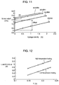
- Fig. 11, showing the result, is a characteristic diagram of hydrogen concentration output when heater element 1 generates high-temperature heat and the hydrogen is humidified. The horizontal axis shows hydrogen concentration (%) passed through the gas sensor, and the vertical axis shows normalized sensor output (%H 2 ).
- Fig. 11 indicates that, if moisture is contained in the ambience, the sensor output changes due to the moisture so largely that it cannot be neglected, and both hydrogen sensing and humidity sensing have the same level of sensitivities. The situation is also the same with L value. Therefore, hydrogen sensing and humidity sensing cannot be performed separately with either L value or H value. Consequently, the gas sensor according to the embodiment outputs both concentrations by performing the calculation shown below.
- the heat conductivity of a gas has temperature dependence, and thus correction for T value, corresponding to an ambient temperature, is made at first for L value and H value. Specifically, zero-point (output for a case where only dry air exists) corrections are made first. Those corrections are made with correcting formulas which are evolved from T values, L values, and H values, which are outputs while dry air is passed through gas sensor 24 at various temperatures. The actual output examples are shown in Fig. 12.
- Fig. 12 shows a result of plotting points in which L values and H values output at ambient temperatures of -40, 20 , 50 , 80 , and 95° C are indicated with the vertical axis, and T values, corresponding to an ambient temperature, are indicated with the horizontal axis.
- L0 and H0 which are components influenced by the temperature dependence on the zero-point are obtained by substituting T value corresponding to an ambient temperature into formulas (1) and (2). Therefore, ZL and ZH, which are zero-point-corrected L value and H value output in an arbitrary environment, are obtained by the following formulas.
- formulas (1) through (4) are zero-point correcting formulas for correcting L value and H value from T value corresponding to an ambient temperature.
- ZL L - L0
- ZH H - H0
- formulas (1) and (2) adopt quadratic approximation, substantially reducing correction errors compared to linear approximation.
- Fig. 13 shows actual temperature dependence of ZL and ZH, which are output for dry air including 1% hydrogen (i.e. 1% hydrogen sensitivity).
- the ambient temperature is changed in the same way as in the zero-point correction.
- the points are plotted with the horizontal axis as T values (corresponding to an ambient temperature), and with the vertical axis as ZL and ZH, respectively.
- Fig. 13 indicates that the sensitivity for 1% hydrogen also has temperature dependence.
- ZH1 0.0996 ⁇ T 2 + 0.0566 ⁇ T - 0.0623
- ZL1 and ZH1 are sensitivity-correcting coefficients by temperature.
- KL and KH which are values of ZL and ZH output in an arbitrary environment, sensitivity-corrected and normalized to hydrogen concentrations, are obtained by the following formulas.
- formulas (5) through (8) are sensitivity-correcting formulas for heater element 1 obtained in advance from a concentration-known gas to be sensed.
- KL ZL/ZL1
- KH ZH/ZH1
- KL and KH obtained with formulas (7) and (8) are outputs normalized with hydrogen concentration. Consequently, the difference between both of them corresponds to the output in an arbitrary environment with the influence by hydrogen concentration deducted, namely, humidity. This is based on that the influence on both heat conductivities can be approximated as a simple sum, for air with hydrogen and vapor mixed therein, as long as hydrogen is contained up to approximately 4%. In other words, if the hydrogen concentration is within 4%, the output sensitivity of hydrogen concentration is as the same level as that of humidity. In addition, this hydrogen concentration is under explosion limit.
- Fig. 14 shows the result of the plotted correlation between the actual difference and the humidity.
- Fig. 14 indicates that the correlation of RH to "Hum", unlike in a conventional technology, does not have a nonlinear characteristic with a peak, but a substantially linear characteristic allowing humidity to be determined uniquely.
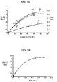
- Fig. 15 is a correlation diagram of KL, KH, and "Hum” to humidity RH in humid air not including hydrogen, where the horizontal axis shows humidity; the left vertical axis, KL and KH; the right vertical axis, "Hum", respectively.
- Fig. 15 indicates that the characteristics of normalized output KL and KH to humidity are all nonlinear characteristics having a peak. This is because the heat conduction characteristic that humid air has is directly shown. Therefore, approximate formulas for KL and KH to humidity must be expressed with a quadratic equation or one with a higher order. Accordingly, solving simultaneous equations using this approximate formula (estimation equation) like a conventional method brings a plurality of solutions, disabling humidity and eventually hydrogen concentration to be uniquely determined.
- Fig. 15 indicates that "Hum” to humidity RH has a substantially linear characteristic, also supporting the theoretical calculation. From these, while the conventional method cannot uniquely determine humidity, the calculation method according to the present invention can uniquely determine humidity by using formula (9).
- Fig. 11 indicates that humidity correction can be made by deducting an offset according to humidity. Therefore, obtaining the correlation between humidity and the offset enables humidity correction.
- Fig. 14 indicates that "Hum” and humidity have a linear relation, and thus the correlation between "Hum” and offset “Off” is shown in Fig. 16, where the horizontal axis shows “Hum”, and the vertical axis shows “Off” obtained from Fig. 11.
- Fig. 16 indicates that offset amount "Off”, which is to be deducted from “Hum”, can be uniquely determined.
- the calculation formula is shown below that is the correlation between both "Hum” and “Off” cubic-approximated with least-square method.
- Formula (10) adopting cubic approximation, reduces correction errors compared to a lower-dimensional approximation.
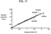
- Fig. 17 shows the actual output in Fig. 11, humidity-corrected with the above-mentioned correction method, where the horizontal axis shows hydrogen concentration in a non sensed gas, and the vertical axis shows hydrogen output "Out".
- Fig. 17 clearly indicates that humidity correction is extremely favorably performed as compared to Fig. 11.
- Calculator 27 when T value, L value, and H value are input, which are output from heater element 1 obtained while the gas sensor is operating, performs the calculation for above-mentioned formulas (1) through (11), to output hydrogen and humidity.
- Fig. 18 shows a flowchart of a subroutine for this calculation procedure.
- an ambient temperature may be output from T value as required.
- this embodiment describes a case where vapor and hydrogen coexist, also for a combination with a gas other than hydrogen, the concentration of the gas can be output in the same way.
- a gas sensor includes a heater element that contacts a gas to be sensed, mixed in the atmospheric air containing moisture; a power supply unit for supplying the heater element with a current; and a voltmeter for measuring a voltage across the heater element.
- the gas sensor further includes a calculator for calculating and outputting the humidity and concentration of a gas to be sensed from output voltages of the voltmeter.
- the calculator supplies the heater element with at least three levels of current, stepwise and continuously for a predetermined time, using the power supply unit. Then, the calculator loads voltages across the heater element after a predetermined elapsed time for the respective current values, and calculates the temperature from the voltage across the heater element for the minimum amount of current.
- the calculator From a zero-point correcting formula and a sensitivity-correcting formula, obtained in advance with the temperature and a concentration-known gas to be sensed, the calculator corrects the voltages across the heater element when passing a current other than the above-mentioned minimum current, to obtain respective normalized outputs. From the difference in these normalized outputs, the calculator calculates humidity, and corrects the normalized outputs with the humidity and a humidity-correcting formula, obtained in advance with a concentration-known gas to be sensed, to obtain the concentration of the gas to be sensed. In such a way, the gas sensor outputs humidity and the concentration of a gas to be sensed.
- the present invention provides a gas sensor that can sense a gas well accurately by distinguishing the concentration of the gas and the humidity each other even if the gas contains moisture. It is suitable to use the gas sensor to sense hydrogen concentration for a fuel cell system and an automobile with a fuel cell mounted thereon.
Landscapes
- Chemical & Material Sciences (AREA)
- Life Sciences & Earth Sciences (AREA)
- Chemical Kinetics & Catalysis (AREA)
- Electrochemistry (AREA)
- Engineering & Computer Science (AREA)
- Manufacturing & Machinery (AREA)
- Sustainable Development (AREA)
- Sustainable Energy (AREA)
- General Chemical & Material Sciences (AREA)
- Health & Medical Sciences (AREA)
- Physics & Mathematics (AREA)
- Analytical Chemistry (AREA)
- Biochemistry (AREA)
- General Health & Medical Sciences (AREA)
- General Physics & Mathematics (AREA)
- Immunology (AREA)
- Pathology (AREA)
- Investigating Or Analyzing Materials By The Use Of Electric Means (AREA)
- Fuel Cell (AREA)
- Electric Propulsion And Braking For Vehicles (AREA)
Applications Claiming Priority (3)
| Application Number | Priority Date | Filing Date | Title |
|---|---|---|---|
| JP2003152489 | 2003-05-29 | ||
| JP2003152489A JP4165300B2 (ja) | 2003-05-29 | 2003-05-29 | ガスセンサとそれを用いた燃料電池システムおよび自動車 |
| PCT/JP2004/007030 WO2004106909A1 (fr) | 2003-05-29 | 2004-05-18 | Detecteur de gaz, systeme de pile a combustible l'utilisant et automobile |
Publications (2)
| Publication Number | Publication Date |
|---|---|
| EP1510814A1 true EP1510814A1 (fr) | 2005-03-02 |
| EP1510814A4 EP1510814A4 (fr) | 2008-06-25 |
Family
ID=33487256
Family Applications (1)
| Application Number | Title | Priority Date | Filing Date |
|---|---|---|---|
| EP04733655A Withdrawn EP1510814A4 (fr) | 2003-05-29 | 2004-05-18 | Detecteur de gaz, systeme de pile a combustible l'utilisant et automobile |
Country Status (4)
| Country | Link |
|---|---|
| US (1) | US7058518B2 (fr) |
| EP (1) | EP1510814A4 (fr) |
| JP (1) | JP4165300B2 (fr) |
| WO (1) | WO2004106909A1 (fr) |
Cited By (5)
| Publication number | Priority date | Publication date | Assignee | Title |
|---|---|---|---|---|
| WO2012171783A1 (fr) * | 2011-06-15 | 2012-12-20 | Siemens Aktiengesellschaft | Dispositif et procédé pour la détermination de la teneur en dioxyde de carbone de l'air |
| CN107004887A (zh) * | 2014-12-09 | 2017-08-01 | 祖迪雅克航空技术公司 | 自主飞行器燃料电池系统 |
| EP3598127A1 (fr) * | 2018-07-19 | 2020-01-22 | Honeywell International Inc. | Procédé de détection de concentration de gaz et dispositif de détection de gaz |
| EP4027417A1 (fr) * | 2021-01-07 | 2022-07-13 | AVL List GmbH | Capteur à double fonction de mesure d'hydrogène et de l'humidité dans la boucle anodique d'un système de pile à combustible |
| US11561208B2 (en) | 2018-12-17 | 2023-01-24 | Siemens Aktiengesellschaft | Thermoresistive gas sensor |
Families Citing this family (31)
| Publication number | Priority date | Publication date | Assignee | Title |
|---|---|---|---|---|
| JP2006250579A (ja) * | 2005-03-08 | 2006-09-21 | Denso Corp | 湿度センサの検査装置及び特性調整方法 |
| JP4692026B2 (ja) * | 2005-03-08 | 2011-06-01 | パナソニック株式会社 | ガスセンサ |
| JP2006327396A (ja) * | 2005-05-26 | 2006-12-07 | Honda Motor Co Ltd | 燃料電池自動車の水素センサ取り付け構造 |
| JP5103751B2 (ja) * | 2006-02-17 | 2012-12-19 | トヨタ自動車株式会社 | 燃料電池システム |
| JP2007285849A (ja) * | 2006-04-17 | 2007-11-01 | Yazaki Corp | ガス濃度検出装置 |
| KR100786480B1 (ko) | 2006-11-30 | 2007-12-17 | 삼성에스디아이 주식회사 | 모듈형 연료전지 시스템 |
| KR100811982B1 (ko) | 2007-01-17 | 2008-03-10 | 삼성에스디아이 주식회사 | 연료 전지 시스템 및 그 제어 방법 |
| US7841228B2 (en) * | 2007-02-05 | 2010-11-30 | Toyota Motor Engineering & Manufacturing North America, Inc. | Method of detecting hydrogen sensor saturation in a hydrogen powered fuel cell |
| US7576660B2 (en) * | 2007-05-30 | 2009-08-18 | Ford Global Technologies, Llc | Fuel retention monitoring system for a pressurized hydrogen storage tank on a vehicle and method of use |
| JP4277925B2 (ja) * | 2007-10-10 | 2009-06-10 | トヨタ自動車株式会社 | ガス検出システム、車両、およびガス検出システムの点検方法 |
| FR2950740A1 (fr) | 2009-09-25 | 2011-04-01 | Michelin Soc Tech | Reacteur electrochimique, tel qu'une pile a combustible ou un electrolyseur, equipe d'un dispositif de mesure de la concentration en un gaz de l'un des gaz specifiques de l'operation dudit reacteur |
| JP2012047659A (ja) * | 2010-08-30 | 2012-03-08 | Hitachi-Ge Nuclear Energy Ltd | 湿度補正機能付き水素濃度測定装置 |
| JP2016012946A (ja) * | 2012-10-30 | 2016-01-21 | 三洋電機株式会社 | 蓄電池モジュールを搭載した車両 |
| JP6189693B2 (ja) * | 2013-09-26 | 2017-08-30 | トヨタ自動車株式会社 | 燃料電池搭載車両 |
| CN105705941A (zh) * | 2013-11-15 | 2016-06-22 | 本田技研工业株式会社 | 气体传感器 |
| US9835574B2 (en) * | 2014-07-02 | 2017-12-05 | Stmicroelectronics S.R.L. | Gas measurement device and measurement method thereof |
| JP6660105B2 (ja) * | 2015-06-11 | 2020-03-04 | 新コスモス電機株式会社 | 気体熱伝導式ガスセンサおよび気体熱伝導式ガスセンサの出力補正方法 |
| US10473604B2 (en) * | 2015-06-30 | 2019-11-12 | GM Global Technology Operations LLC | Method of determining deformation location |
| EP3343212B1 (fr) * | 2015-08-28 | 2019-11-06 | Panasonic Intellectual Property Management Co., Ltd. | Capteur de gaz et véhicule à pile à combustible |
| JP6722989B2 (ja) * | 2015-08-31 | 2020-07-15 | 日立オートモティブシステムズ株式会社 | 気体センサ装置 |
| JP6534937B2 (ja) * | 2016-01-13 | 2019-06-26 | 日本特殊陶業株式会社 | 可燃性ガス検出装置 |
| JP6761764B2 (ja) * | 2016-03-18 | 2020-09-30 | パナソニックセミコンダクターソリューションズ株式会社 | 水素センサ及び燃料電池自動車、並びに水素検出方法 |
| JP6738749B2 (ja) * | 2016-03-25 | 2020-08-12 | パナソニックセミコンダクターソリューションズ株式会社 | 気体センサ、水素検出方法、及び燃料電池自動車 |
| CN107315033B (zh) * | 2016-04-26 | 2021-08-06 | 新唐科技日本株式会社 | 气体检测装置以及氢检测方法 |
| JP7325006B2 (ja) * | 2018-03-30 | 2023-08-14 | パナソニックIpマネジメント株式会社 | ガス成分計測装置 |
| JP7606973B2 (ja) * | 2019-03-13 | 2024-12-26 | ラム リサーチ コーポレーション | 温度を近似させるための静電チャックヒータ抵抗測定 |
| US11162928B2 (en) * | 2019-11-04 | 2021-11-02 | Invensense, Inc. | Humidity correction method in thermistor based gas sensing platform |
| CN114034751B (zh) * | 2021-11-11 | 2024-09-17 | 中煤科工集团重庆研究院有限公司 | 一种提高传感器工作稳定性时间的自学习方法 |
| JP7721221B2 (ja) * | 2022-02-08 | 2025-08-12 | 理研計器株式会社 | ガス検知器 |
| DE102023110687A1 (de) * | 2022-05-23 | 2023-11-23 | Dräger Safety AG & Co. KGaA | Gasdetektionsvorrichtung und Gasdetektionsverfahren mit automatischer Störgrößen-Kompensation |
| JP7839132B2 (ja) * | 2023-08-24 | 2026-04-01 | 株式会社東芝 | センサ |
Family Cites Families (11)
| Publication number | Priority date | Publication date | Assignee | Title |
|---|---|---|---|---|
| JPS5814045A (ja) * | 1981-07-17 | 1983-01-26 | Matsushita Electric Ind Co Ltd | 複数ガス濃度計測装置 |
| US5366821A (en) * | 1992-03-13 | 1994-11-22 | Ballard Power Systems Inc. | Constant voltage fuel cell with improved reactant supply and control system |
| JPH06223850A (ja) * | 1993-01-29 | 1994-08-12 | Mitsubishi Heavy Ind Ltd | 固体高分子電解質燃料電池の運転保護システム |
| JP2889909B2 (ja) * | 1993-08-10 | 1999-05-10 | リコーエレメックス株式会社 | 雰囲気計 |
| JPH0850109A (ja) * | 1994-08-08 | 1996-02-20 | Yamatake Honeywell Co Ltd | ガス分析方法 |
| JP3321315B2 (ja) * | 1994-10-03 | 2002-09-03 | リコーエレメックス株式会社 | 大気ガス検出装置 |
| JP3343801B2 (ja) * | 1994-12-29 | 2002-11-11 | 光照 木村 | 湿度センサ |
| JP3546097B2 (ja) * | 1995-06-22 | 2004-07-21 | 株式会社ガスター | Coセンサ |
| JP4131038B2 (ja) * | 1998-06-26 | 2008-08-13 | 株式会社エクォス・リサーチ | 燃料電池システム |
| US6532792B2 (en) * | 2001-07-26 | 2003-03-18 | Avista Laboratories, Inc. | Method of compensating a MOS gas sensor, method of manufacturing a MOS gas sensor, MOS gas sensor, and fuel cell system |
| JP2003098147A (ja) * | 2001-09-25 | 2003-04-03 | Matsushita Electric Ind Co Ltd | 水素センサとそれを用いた自動車 |
-
2003
- 2003-05-29 JP JP2003152489A patent/JP4165300B2/ja not_active Expired - Fee Related
-
2004
- 2004-05-18 WO PCT/JP2004/007030 patent/WO2004106909A1/fr not_active Ceased
- 2004-05-18 US US10/515,863 patent/US7058518B2/en not_active Expired - Fee Related
- 2004-05-18 EP EP04733655A patent/EP1510814A4/fr not_active Withdrawn
Cited By (9)
| Publication number | Priority date | Publication date | Assignee | Title |
|---|---|---|---|---|
| WO2012171783A1 (fr) * | 2011-06-15 | 2012-12-20 | Siemens Aktiengesellschaft | Dispositif et procédé pour la détermination de la teneur en dioxyde de carbone de l'air |
| CN103635796A (zh) * | 2011-06-15 | 2014-03-12 | 西门子公司 | 用于测定空气中二氧化碳含量的设备和方法 |
| US9523665B2 (en) | 2011-06-15 | 2016-12-20 | Siemens Aktiengesellschaft | Device and method for determining carbon dioxide content of air |
| CN107004887A (zh) * | 2014-12-09 | 2017-08-01 | 祖迪雅克航空技术公司 | 自主飞行器燃料电池系统 |
| US10710739B2 (en) | 2014-12-09 | 2020-07-14 | Zodiac Aerotechnics | Autonomous aircraft fuel cell system |
| EP3598127A1 (fr) * | 2018-07-19 | 2020-01-22 | Honeywell International Inc. | Procédé de détection de concentration de gaz et dispositif de détection de gaz |
| US11561208B2 (en) | 2018-12-17 | 2023-01-24 | Siemens Aktiengesellschaft | Thermoresistive gas sensor |
| EP3671195B1 (fr) * | 2018-12-17 | 2025-02-12 | Siemens Aktiengesellschaft | Capteur de gaz thermorésistif |
| EP4027417A1 (fr) * | 2021-01-07 | 2022-07-13 | AVL List GmbH | Capteur à double fonction de mesure d'hydrogène et de l'humidité dans la boucle anodique d'un système de pile à combustible |
Also Published As
| Publication number | Publication date |
|---|---|
| EP1510814A4 (fr) | 2008-06-25 |
| US7058518B2 (en) | 2006-06-06 |
| JP4165300B2 (ja) | 2008-10-15 |
| US20050228596A1 (en) | 2005-10-13 |
| JP2004354210A (ja) | 2004-12-16 |
| WO2004106909A1 (fr) | 2004-12-09 |
Similar Documents
| Publication | Publication Date | Title |
|---|---|---|
| US7058518B2 (en) | Gas sensor, fuel cell system therewith, and automobile therewith | |
| US7360396B2 (en) | Gas sensor and fuel cell system and automobile employing the same | |
| JP4016813B2 (ja) | ガス検出器とそれを用いた燃料電池システムおよび自動車 | |
| JP2004191164A (ja) | ガスセンサとそれを用いた燃料電池システムおよび自動車 | |
| US20080282771A1 (en) | Apparatus and method for detecting combustible gas within atmosphere to be detected | |
| JP5373474B2 (ja) | 可燃性ガス検出装置 | |
| US10859523B2 (en) | Gas sensor | |
| JP7721221B2 (ja) | ガス検知器 | |
| US20130180854A1 (en) | Correction coefficient setting method of gas concentration detection apparatus, gas concentration detection apparatus and gas sensor | |
| CN114830405A (zh) | 能够检测损坏的电池单体的电池系统和电池模块评估方法 | |
| JP2013033016A (ja) | 酸素拡散係数測定装置および酸素拡散係数測定方法 | |
| JP2007309905A (ja) | ガス検出器 | |
| JP2008267948A (ja) | ガス検出装置およびガス検出方法 | |
| JP2007248356A (ja) | 可燃性ガス検出装置及び可燃性ガス検出方法 | |
| JP2004028716A (ja) | ガス検出器とそれを用いた燃料電池システムおよび自動車 | |
| JP3986984B2 (ja) | 接触燃焼式水素センサの較正方法 | |
| JP2010091299A (ja) | 可燃性ガス検出装置 | |
| JP4045549B2 (ja) | 水素濃度検出装置及び水素濃度検出方法 | |
| JP2005043208A (ja) | ガスセンサとそれを用いた燃料電池システムおよび自動車 | |
| JP5021400B2 (ja) | 可燃性ガス検出装置 | |
| JP2003130834A (ja) | 水素センサとそれを用いた自動車 | |
| JP2004177263A (ja) | 湿度センサおよびそれを用いた燃料電池システム、自動車および調理機器 | |
| JP2008008677A (ja) | 電気素子の温度測定方法及び負荷試験装置 | |
| US20260118333A1 (en) | Hybrid hydrogen sensor and method of controlling the same | |
| JP2005172655A (ja) | ガスセンサとそれを用いた燃料電池システムおよび自動車 |
Legal Events
| Date | Code | Title | Description |
|---|---|---|---|
| PUAI | Public reference made under article 153(3) epc to a published international application that has entered the european phase |
Free format text: ORIGINAL CODE: 0009012 |
|
| 17P | Request for examination filed |
Effective date: 20041118 |
|
| AK | Designated contracting states |
Kind code of ref document: A1 Designated state(s): AT BE BG CH CY CZ DE DK EE ES FI FR GB GR HU IE IT LI LU MC NL PL PT RO SE SI SK TR |
|
| AX | Request for extension of the european patent |
Extension state: AL HR LT LV MK |
|
| DAX | Request for extension of the european patent (deleted) | ||
| RBV | Designated contracting states (corrected) |
Designated state(s): DE FR GB |
|
| A4 | Supplementary search report drawn up and despatched |
Effective date: 20080526 |
|
| RIC1 | Information provided on ipc code assigned before grant |
Ipc: H01M 8/04 20060101ALI20080519BHEP Ipc: G01N 33/00 20060101ALI20080519BHEP Ipc: G01N 27/18 20060101AFI20041215BHEP |
|
| RAP1 | Party data changed (applicant data changed or rights of an application transferred) |
Owner name: PANASONIC CORPORATION |
|
| 17Q | First examination report despatched |
Effective date: 20090112 |
|
| STAA | Information on the status of an ep patent application or granted ep patent |
Free format text: STATUS: THE APPLICATION IS DEEMED TO BE WITHDRAWN |
|
| 18D | Application deemed to be withdrawn |
Effective date: 20121201 |