EP1510824A1 - Sensoranordnung zur Messung der Drehzahl eines Rades - Google Patents
Sensoranordnung zur Messung der Drehzahl eines Rades Download PDFInfo
- Publication number
- EP1510824A1 EP1510824A1 EP03103222A EP03103222A EP1510824A1 EP 1510824 A1 EP1510824 A1 EP 1510824A1 EP 03103222 A EP03103222 A EP 03103222A EP 03103222 A EP03103222 A EP 03103222A EP 1510824 A1 EP1510824 A1 EP 1510824A1
- Authority
- EP
- European Patent Office
- Prior art keywords
- sensor
- carrier
- head
- locking element
- rotational speed
- Prior art date
- Legal status (The legal status is an assumption and is not a legal conclusion. Google has not performed a legal analysis and makes no representation as to the accuracy of the status listed.)
- Granted
Links
- 239000000725 suspension Substances 0.000 claims description 7
- 229910000639 Spring steel Inorganic materials 0.000 claims description 3
- 238000005538 encapsulation Methods 0.000 claims description 3
- 239000000523 sample Substances 0.000 description 3
- 238000005266 casting Methods 0.000 description 1
- 238000010276 construction Methods 0.000 description 1
- 238000004519 manufacturing process Methods 0.000 description 1
- 239000000463 material Substances 0.000 description 1
- 238000005259 measurement Methods 0.000 description 1
Images
Classifications
-
- G—PHYSICS
- G01—MEASURING; TESTING
- G01P—MEASURING LINEAR OR ANGULAR SPEED, ACCELERATION, DECELERATION, OR SHOCK; INDICATING PRESENCE, ABSENCE, OR DIRECTION, OF MOVEMENT
- G01P1/00—Details of instruments
- G01P1/02—Housings
- G01P1/026—Housings for speed measuring devices, e.g. pulse generator
-
- G—PHYSICS
- G01—MEASURING; TESTING
- G01P—MEASURING LINEAR OR ANGULAR SPEED, ACCELERATION, DECELERATION, OR SHOCK; INDICATING PRESENCE, ABSENCE, OR DIRECTION, OF MOVEMENT
- G01P1/00—Details of instruments
Definitions
- the invention relates to a sensor sensor for measuring the rotational speed of a motor vehicle wheel and a sensor arrangement comprising such a sensor sensor contains.
- ABS Anti-lock braking systems
- DE 693 18 250 T2 discloses in this context a sensor system, in which a permanent magnet on the wheel shaft and a sensor sensor on the steering knuckle the suspension is attached.
- a Hall probe registers the magnetic field and issued a corresponding count.
- the substantially rod-shaped sensor head is in a through hole of the steering knuckle, with a rubber O-ring for a seal and Fixation by friction ensures.
- a fuse of the sensor sensor in the assembled state by a fuse pin not explained in more detail mentioned.
- the sensor sensor fixed by screws to the suspension.
- an object of the present invention was to to provide a more easily mountable sensor system.
- the sensor sensor according to the invention serves to measure the rotational speed of a motor vehicle wheel, he in this regard z. B. on known principles such as the Ve r-use a Hall probe for measuring a magnetic field can be based.
- the Sensor sensor contains a substantially rod-shaped sensor head, which in mounted state of the sensor sensor in a corresponding opening of the Wheel suspension belonging carrier is arranged.
- the sensor sensor is thereby characterized in that a detent element is firmly connected to it, which is the Sensor sensor fixed in its mounted state on said support.
- a sensor sensor of the construction described has the advantage that it is particularly simply mounted on a suspension and in case of need again from this element can be dismantled. There is no time-consuming screwing or attachment of safety bolts required. Of particular advantage is further that due to the one-piece bond between sensor sensor and locking element no separate part - such as a screw or a Bolt - must be present, which on the one hand in fine craftsmanship would have to be used and which on the other hand brings the risk, easy to get lost.
- the locking element formed as a spring tongue, which is substantially parallel and spaced extends to the sensor head.
- the spring tongue has a slight inclination towards the sensor head.
- the sensor head and the spring tongue pinching a part of the carrier between them, whereby the sensor head is securely fixed.
- the arrangement also has the advantage that these are very tolerant to variances in terms of spring properties the shape and dimensions of the carrier.
- the locking element may in particular consist of a spring steel, so that it with appropriate elasticity has a high durability and stability.
- the latching element is integrally connected to the sensor housing.
- it may be embedded by encapsulation in the sensor housing.
- the material connection is an optimal connection between the sensor and reaches the locking element, which in addition by casting relatively can easily generate in the course of the production of the sensor housing.
- the invention further relates to a sensor arrangement for measuring the rotational speed of Wheel of a motor vehicle, wherein the sensor arrangement is a sensor sensor of as explained above and a vehicle belonging to the suspension contains for receiving the sensor sensor.
- the carrier is further characterized that this an opening for receiving the sensor head of the sensor sensor and a substantially parallel to this opening extending Having recess for receiving the locking element of the sensor sensor.
- the sensor sensor with its sensor head be inserted into the opening, at the same time the locking element in the Locking recess of the carrier and thereby fixes the sensor sensor.
- the recess of the carrier preferably has at least one radial recess on, in which the locking element can engage.
- the longitudinal extent of the sensor head an "axial" direction, wherein the These vertical directions are referred to as "radial”.
- the thus defined with respect to the sensor head or the opening of the carrier Directions apply analogously to the recess lying parallel to the opening.
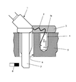
- the single FIGURE shows a sensor sensor according to the invention in a carrier assembled state in a partially sectioned view.
- the sensor sensor 1 shown schematically in the figure is used to measure the Wheel speed, the knowledge of which, for example, requires an anti-lock braking system becomes.
- the sensor sensor 1 has a substantially rod-shaped sensor head 7 which is inserted through a cylindrical passage opening 6 of a carrier 5 is.
- the carrier 5 is a non-rotating part of the suspension, for example the steering knuckle.
- the protruding from the passage opening 6 Part of the sensor head 7 is positioned in the illustrated state that he a Permanent magnet 8 comes close.
- the magnet 8 is not shown in detail Way with a rotating part of the wheel such. B. the wheel shaft connected. With each revolution of the wheel, the magnet 8 thus strokes once on the sensor head 7 over, so that a Hall sensor (not shown) arranged therein Register magnetic field and can give a count.
- a clip or latching mechanism provided for mounting and fixing the sensor sensor 1 on the carrier 5 is according to the invention.
- This includes a fixed with the sensor sensor 1 connected locking element 2, as a clip from bent spring steel is formed.
- the locking element 2 is provided with one end in a radial arm 3 of the sensor housing embedded by encapsulation.
- the formed as a spring tongue 2a other end of the locking element 2 protrudes from the Sensor housing 3 out and extends substantially parallel to the rod-shaped Sensor head 7, d. H. by definition in the axial direction A.
- it has a slight tendency to point to the sensor head 7.
- the freestanding spring tongue 2a is as shown in the assembled state in a Tapped hole 4 is inserted, extending in the carrier 5 parallel to the passage opening 6 extends.
- the thread grooves make recesses in the radial direction R (i.e., perpendicular to the axial direction A) into which the spring tongue 2a can engage during assembly of the sensor sensor 1.
- the sensor sensor is thereby axially fixed in the reached end position against unwanted withdrawal.
- the recess 4 could also have a groove, a heel or any other undercut contain, in which the spring tongue 2a could snap.
- the locking element 2 is otherwise dimensioned so that the between him and the sensor head 7 lying area of the carrier 5 is clamped is, whereby a secure fit of the sensor sensor 1 is ensured.
Landscapes
- Physics & Mathematics (AREA)
- General Physics & Mathematics (AREA)
- Regulating Braking Force (AREA)
- Measurement Of Length, Angles, Or The Like Using Electric Or Magnetic Means (AREA)
- Vehicle Body Suspensions (AREA)
Abstract
Description
Claims (7)
- Sensorfühler (1) zur Messung der Drehzahl eines Kraftfahrzeugrades, enthaltend einen im Wesentlichen stabförmigen Sensorkopf (7), welcher im montierten Zustand in der Öffnung (6) eines Trägers (5) angeordnet ist,
dadurch gekennzeichnet, daß
mit dem Sensorfühler (1) ein Rastelement (2) verbunden ist, welches im montierten Zustand den Sensorfühler an dem Träger (5) fixiert. - Sensorfühler nach Anspruch 1,
dadurch gekennzeichnet, daß
das Rastelement (2) eine sich im Wesentlichen parallel und beabstandet zum Sensorkopf (7) erstreckende Federzunge (2a) aufweist. - Sensorfühler nach Anspruch 1 oder 2,
dadurch gekennzeichnet, daß
das Rastelement (2) aus Federstahl besteht. - Sensorfühler nach mindestens einem der Ansprüche 1 bis 3,
dadurch gekennzeichnet, daß
das Rastelement (2) mit dem Sensorgehäuse (3) stoffschlüssig verbunden ist. - Sensorfühler nach Anspruch 4,
dadurch gekennzeichnet, daß
das Rastelement (2) im Sensorgehäuse (3) durch Verguß eingebettet ist. - Sensoranordnung zur Messung der Drehzahl eines Kraftfahrzeugrades, enthaltend einen Sensorfühler (1) nach mindestens einem der Ansprüche 1 bis 5 sowie einen zur Radaufhängung gehörenden Träger (5) für den Sensorfühler (1), wobei der Träger (5) eine Öffnung (6) zur Aufnahme des Sensorkopfes (7) sowie eine sich parallel zu dieser Öffnung erstreckende Ausnehmung (4) zur Aufnahme des Rastelementes (2) aufweist.
- Sensoranordnung nach Anspruch 6,
dadurch gekennzeichnet, daß
die Ausnehmung (4) des Trägers (5) mindestens eine radiale Vertiefung aufweist, in welche das Rastelement (2) eingreifen kann.
Priority Applications (2)
| Application Number | Priority Date | Filing Date | Title |
|---|---|---|---|
| DE50305962T DE50305962D1 (de) | 2003-08-26 | 2003-08-26 | Sensoranordnung zur Messung der Drehzahl eines Rades |
| EP20030103222 EP1510824B1 (de) | 2003-08-26 | 2003-08-26 | Sensoranordnung zur Messung der Drehzahl eines Rades |
Applications Claiming Priority (1)
| Application Number | Priority Date | Filing Date | Title |
|---|---|---|---|
| EP20030103222 EP1510824B1 (de) | 2003-08-26 | 2003-08-26 | Sensoranordnung zur Messung der Drehzahl eines Rades |
Publications (2)
| Publication Number | Publication Date |
|---|---|
| EP1510824A1 true EP1510824A1 (de) | 2005-03-02 |
| EP1510824B1 EP1510824B1 (de) | 2006-12-13 |
Family
ID=34089730
Family Applications (1)
| Application Number | Title | Priority Date | Filing Date |
|---|---|---|---|
| EP20030103222 Expired - Lifetime EP1510824B1 (de) | 2003-08-26 | 2003-08-26 | Sensoranordnung zur Messung der Drehzahl eines Rades |
Country Status (2)
| Country | Link |
|---|---|
| EP (1) | EP1510824B1 (de) |
| DE (1) | DE50305962D1 (de) |
Cited By (1)
| Publication number | Priority date | Publication date | Assignee | Title |
|---|---|---|---|---|
| ITPD20120217A1 (it) * | 2012-07-06 | 2014-01-07 | Ln 2 Srl Socio Unico | Supporto per un sensore di rotazione in gruppi motore-girante di elettro-ventilatori |
Families Citing this family (1)
| Publication number | Priority date | Publication date | Assignee | Title |
|---|---|---|---|---|
| FR3121210A1 (fr) * | 2021-03-26 | 2022-09-30 | Renault S.A.S | Ensemble comportant un support et un capteur de la vitesse de rotation d’une roue de vehicule automobile |
Citations (2)
| Publication number | Priority date | Publication date | Assignee | Title |
|---|---|---|---|---|
| GB1455400A (en) * | 1973-11-27 | 1976-11-10 | Teldix Gmbh | Stator arrangement for an electrical rotary speed signal generator |
| JPH09175354A (ja) * | 1995-12-28 | 1997-07-08 | Suzuki Motor Corp | センサ取付構造 |
-
2003
- 2003-08-26 DE DE50305962T patent/DE50305962D1/de not_active Expired - Lifetime
- 2003-08-26 EP EP20030103222 patent/EP1510824B1/de not_active Expired - Lifetime
Patent Citations (2)
| Publication number | Priority date | Publication date | Assignee | Title |
|---|---|---|---|---|
| GB1455400A (en) * | 1973-11-27 | 1976-11-10 | Teldix Gmbh | Stator arrangement for an electrical rotary speed signal generator |
| JPH09175354A (ja) * | 1995-12-28 | 1997-07-08 | Suzuki Motor Corp | センサ取付構造 |
Non-Patent Citations (2)
| Title |
|---|
| "TWO INTERNAL SNAP-IN SPEED SENSORS FOR AUTOMATIC TRANSMISSIONS", RESEARCH DISCLOSURE, KENNETH MASON PUBLICATIONS, HAMPSHIRE, GB, no. 402, 1 October 1997 (1997-10-01), pages 738, XP000726873, ISSN: 0374-4353 * |
| PATENT ABSTRACTS OF JAPAN vol. 1997, no. 11 28 November 1997 (1997-11-28) * |
Cited By (2)
| Publication number | Priority date | Publication date | Assignee | Title |
|---|---|---|---|---|
| ITPD20120217A1 (it) * | 2012-07-06 | 2014-01-07 | Ln 2 Srl Socio Unico | Supporto per un sensore di rotazione in gruppi motore-girante di elettro-ventilatori |
| EP2682757A1 (de) * | 2012-07-06 | 2014-01-08 | LN 2 S.R.L. a socio unico | Halter für einen Drehsensor in Motorflügelradeinheiten elektrischer Lüfter |
Also Published As
| Publication number | Publication date |
|---|---|
| DE50305962D1 (de) | 2007-01-25 |
| EP1510824B1 (de) | 2006-12-13 |
Similar Documents
| Publication | Publication Date | Title |
|---|---|---|
| DE1961846C3 (de) | Drehzahlgeber zur Bestimmung der Drehzahl oder Drehzahländerung von Fahrzeugrädern, insbesondere für Bremsschlupfregelanlagen von Kraftfahrzeugen | |
| DE4213979A1 (de) | Vorrichtung zur messung von drehbewegungen | |
| DE69318250T2 (de) | Sensorsystem für Antiblockierbremsanlage | |
| DE68908011T2 (de) | Mit einem Pulsgenerator und Sensor ausgestattete nichtangetriebene Kraftfahrzeugnabe, um die Drehzahl des Rades zu messen. | |
| DE4206910A1 (de) | Vorrichtung zur messung von drehbewegungen | |
| DE102005062784A1 (de) | Magnet-Baueinheit zur Befestigung auf einer Welle | |
| WO2014108149A1 (de) | Sensorvorrichtung zur drehzahlmessung an einem rad eines fahrzeugs, bremsanlage für ein fahrzeug und fahrzeug damit sowie verwendung der sensorvorrichtung zur drehzahlmessung an einem rad eines fahrzeugs | |
| DE69117619T2 (de) | Rotierende Kodierhülse für Abtastvorrichtung | |
| EP3390999A1 (de) | Statorhalter, statorbaugruppe, verfahren zum zusammenbau einer statorbaugruppe, drehmomentsensorvorrichtung mit einer statorbaugruppe und einem statorhalter und kraftfahrzeug mit einer drehmomentsensorvorrichtung | |
| DE2542192A1 (de) | Fahrzeugrad-blockierschutzvorrichtung | |
| EP3859351B1 (de) | Schutzhülse für einen drehzahlsensor und drehzahlsensor mit schutzhülse | |
| DE112016000825T5 (de) | Sensormagnethalterung, Magnetbefestigungsstruktur und Motor | |
| EP1510824A1 (de) | Sensoranordnung zur Messung der Drehzahl eines Rades | |
| DE19532328A1 (de) | Radlagersensor zum Messen von Dreh- oder Winkelbewegungen | |
| DE102017110259B3 (de) | Sensor mit einer Magnetbaugruppe und Verfahren zu dessen Herstellung | |
| DE102019125405A1 (de) | Sensor und System aus dem Sensor und einer Befestigungseinrichtung | |
| DE102010030121A1 (de) | Polradanordnung für einen Drehgeber | |
| DE102010005854B4 (de) | Aktuator | |
| EP2572168B1 (de) | Aufspanneinrichtung für eine masskörpervorrichtung für ein positions-/wegmesssystem | |
| EP3969916B1 (de) | Drehzahlsensor, fixiereinrichtung für einen drehzahlsensor, aufnahmevorrichtung für einen drehzahlsensor, sensorsystem mit einer aufnahmevorrichtung und einem drehzahlsensor und verfahren zum verdrehsicheren positionieren eines drehzahlsensors | |
| DE60019479T2 (de) | Magnethalter für eine Speiche | |
| DE602005001577T2 (de) | Positionssensor | |
| DE10244102B4 (de) | Sensoranordnung zum Erfassen einer umdrehungsbezogenen Grösse eines elektrischen Motors | |
| DE60010153T2 (de) | Magnetische Anordnung für Fahrradüberwachungsgerät | |
| DE2443862A1 (de) | Elektrischer drehgeschwindigkeitsgeber |
Legal Events
| Date | Code | Title | Description |
|---|---|---|---|
| PUAI | Public reference made under article 153(3) epc to a published international application that has entered the european phase |
Free format text: ORIGINAL CODE: 0009012 |
|
| AK | Designated contracting states |
Kind code of ref document: A1 Designated state(s): AT BE BG CH CY CZ DE DK EE ES FI FR GB GR HU IE IT LI LU MC NL PT RO SE SI SK TR |
|
| AX | Request for extension of the european patent |
Extension state: AL LT LV MK |
|
| RAP1 | Party data changed (applicant data changed or rights of an application transferred) |
Owner name: FORD GLOBAL TECHNOLOGIES, LLC |
|
| 17P | Request for examination filed |
Effective date: 20050902 |
|
| AKX | Designation fees paid |
Designated state(s): DE FR GB |
|
| RAP1 | Party data changed (applicant data changed or rights of an application transferred) |
Owner name: FORD GLOBAL TECHNOLOGIES, LLC. |
|
| GRAP | Despatch of communication of intention to grant a patent |
Free format text: ORIGINAL CODE: EPIDOSNIGR1 |
|
| GRAS | Grant fee paid |
Free format text: ORIGINAL CODE: EPIDOSNIGR3 |
|
| GRAA | (expected) grant |
Free format text: ORIGINAL CODE: 0009210 |
|
| AK | Designated contracting states |
Kind code of ref document: B1 Designated state(s): DE FR GB |
|
| REG | Reference to a national code |
Ref country code: GB Ref legal event code: FG4D Free format text: NOT ENGLISH |
|
| REF | Corresponds to: |
Ref document number: 50305962 Country of ref document: DE Date of ref document: 20070125 Kind code of ref document: P |
|
| GBT | Gb: translation of ep patent filed (gb section 77(6)(a)/1977) |
Effective date: 20070315 |
|
| ET | Fr: translation filed | ||
| PLBE | No opposition filed within time limit |
Free format text: ORIGINAL CODE: 0009261 |
|
| STAA | Information on the status of an ep patent application or granted ep patent |
Free format text: STATUS: NO OPPOSITION FILED WITHIN TIME LIMIT |
|
| 26N | No opposition filed |
Effective date: 20070914 |
|
| REG | Reference to a national code |
Ref country code: FR Ref legal event code: PLFP Year of fee payment: 13 |
|
| REG | Reference to a national code |
Ref country code: FR Ref legal event code: PLFP Year of fee payment: 14 |
|
| REG | Reference to a national code |
Ref country code: FR Ref legal event code: PLFP Year of fee payment: 15 |
|
| REG | Reference to a national code |
Ref country code: FR Ref legal event code: PLFP Year of fee payment: 16 |
|
| PGFP | Annual fee paid to national office [announced via postgrant information from national office to epo] |
Ref country code: FR Payment date: 20180718 Year of fee payment: 16 Ref country code: DE Payment date: 20180716 Year of fee payment: 16 |
|
| PGFP | Annual fee paid to national office [announced via postgrant information from national office to epo] |
Ref country code: GB Payment date: 20180726 Year of fee payment: 16 |
|
| REG | Reference to a national code |
Ref country code: DE Ref legal event code: R119 Ref document number: 50305962 Country of ref document: DE |
|
| GBPC | Gb: european patent ceased through non-payment of renewal fee |
Effective date: 20190826 |
|
| PG25 | Lapsed in a contracting state [announced via postgrant information from national office to epo] |
Ref country code: DE Free format text: LAPSE BECAUSE OF NON-PAYMENT OF DUE FEES Effective date: 20200303 Ref country code: FR Free format text: LAPSE BECAUSE OF NON-PAYMENT OF DUE FEES Effective date: 20190831 |
|
| PG25 | Lapsed in a contracting state [announced via postgrant information from national office to epo] |
Ref country code: GB Free format text: LAPSE BECAUSE OF NON-PAYMENT OF DUE FEES Effective date: 20190826 |