EP1510841A1 - Fibre de cristal photonique, son procede de fabrication et son procede de connexion - Google Patents
Fibre de cristal photonique, son procede de fabrication et son procede de connexion Download PDFInfo
- Publication number
- EP1510841A1 EP1510841A1 EP03730745A EP03730745A EP1510841A1 EP 1510841 A1 EP1510841 A1 EP 1510841A1 EP 03730745 A EP03730745 A EP 03730745A EP 03730745 A EP03730745 A EP 03730745A EP 1510841 A1 EP1510841 A1 EP 1510841A1
- Authority
- EP
- European Patent Office
- Prior art keywords
- fiber
- core
- photonic crystal
- microscopic holes
- blocking element
- Prior art date
- Legal status (The legal status is an assumption and is not a legal conclusion. Google has not performed a legal analysis and makes no representation as to the accuracy of the status listed.)
- Withdrawn
Links
- 239000000835 fiber Substances 0.000 title claims abstract description 153
- 239000004038 photonic crystal Substances 0.000 title claims abstract description 58
- 238000000034 method Methods 0.000 title claims description 27
- 239000013078 crystal Substances 0.000 title 1
- 238000004519 manufacturing process Methods 0.000 title 1
- 230000000903 blocking effect Effects 0.000 claims abstract description 56
- 238000005253 cladding Methods 0.000 claims abstract description 37
- 238000005498 polishing Methods 0.000 claims description 55
- 239000013307 optical fiber Substances 0.000 claims description 19
- 239000003795 chemical substances by application Substances 0.000 description 14
- 239000000428 dust Substances 0.000 description 14
- 230000005540 biological transmission Effects 0.000 description 10
- 230000003287 optical effect Effects 0.000 description 9
- 230000035939 shock Effects 0.000 description 5
- 230000009545 invasion Effects 0.000 description 4
- 235000012239 silicon dioxide Nutrition 0.000 description 4
- 239000000126 substance Substances 0.000 description 3
- VYPSYNLAJGMNEJ-UHFFFAOYSA-N Silicium dioxide Chemical compound O=[Si]=O VYPSYNLAJGMNEJ-UHFFFAOYSA-N 0.000 description 2
- 230000006866 deterioration Effects 0.000 description 1
- 239000006185 dispersion Substances 0.000 description 1
- 230000000694 effects Effects 0.000 description 1
- 238000012681 fiber drawing Methods 0.000 description 1
- 229910052732 germanium Inorganic materials 0.000 description 1
- GNPVGFCGXDBREM-UHFFFAOYSA-N germanium atom Chemical compound [Ge] GNPVGFCGXDBREM-UHFFFAOYSA-N 0.000 description 1
- 230000002452 interceptive effect Effects 0.000 description 1
- 239000000377 silicon dioxide Substances 0.000 description 1
- 238000010998 test method Methods 0.000 description 1
Images


Classifications
-
- G—PHYSICS
- G02—OPTICS
- G02B—OPTICAL ELEMENTS, SYSTEMS OR APPARATUS
- G02B6/00—Light guides; Structural details of arrangements comprising light guides and other optical elements, e.g. couplings
- G02B6/02—Optical fibres with cladding with or without a coating
- G02B6/02295—Microstructured optical fibre
- G02B6/02314—Plurality of longitudinal structures extending along optical fibre axis, e.g. holes
- G02B6/02342—Plurality of longitudinal structures extending along optical fibre axis, e.g. holes characterised by cladding features, i.e. light confining region
- G02B6/02347—Longitudinal structures arranged to form a regular periodic lattice, e.g. triangular, square, honeycomb unit cell repeated throughout cladding
-
- G—PHYSICS
- G02—OPTICS
- G02B—OPTICAL ELEMENTS, SYSTEMS OR APPARATUS
- G02B6/00—Light guides; Structural details of arrangements comprising light guides and other optical elements, e.g. couplings
- G02B6/02—Optical fibres with cladding with or without a coating
- G02B6/02295—Microstructured optical fibre
- G02B6/02314—Plurality of longitudinal structures extending along optical fibre axis, e.g. holes
- G02B6/02342—Plurality of longitudinal structures extending along optical fibre axis, e.g. holes characterised by cladding features, i.e. light confining region
- G02B6/02361—Longitudinal structures forming multiple layers around the core, e.g. arranged in multiple rings with each ring having longitudinal elements at substantially the same radial distance from the core, having rotational symmetry about the fibre axis
-
- G—PHYSICS
- G02—OPTICS
- G02B—OPTICAL ELEMENTS, SYSTEMS OR APPARATUS
- G02B6/00—Light guides; Structural details of arrangements comprising light guides and other optical elements, e.g. couplings
- G02B6/24—Coupling light guides
- G02B6/255—Splicing of light guides, e.g. by fusion or bonding
-
- G—PHYSICS
- G02—OPTICS
- G02B—OPTICAL ELEMENTS, SYSTEMS OR APPARATUS
- G02B6/00—Light guides; Structural details of arrangements comprising light guides and other optical elements, e.g. couplings
- G02B6/24—Coupling light guides
- G02B6/36—Mechanical coupling means
- G02B6/38—Mechanical coupling means having fibre to fibre mating means
- G02B6/3807—Dismountable connectors, i.e. comprising plugs
- G02B6/381—Dismountable connectors, i.e. comprising plugs of the ferrule type, e.g. fibre ends embedded in ferrules, connecting a pair of fibres
Definitions
- the present invention relates to a photonic crystal fiber having a fiber body including a core and a cladding (porous part) which is provided to surround the core and has a plurality of microscopic holes extending along the core, and a method for fabricating the same, and a method for connecting fibers.
- photonic crystal fibers include a core which is solidly formed at the fiber center, and a cladding which is provided to surround the core and has a plurality of microscopic holes extending along the core.
- a photonic crystal fiber confines light within a core surrounded with a cladding and transmits the light. Since the photonic crystal fiber can freely control wavelength dispersion of light by changing the size of microscopic holes or the distance therebetween, communication in new wavelengths can be realized, which has not been realized by conventional optical fibers, and an increase in communication speed and a reduction in communication cost are expected.
- the distance between the microscopic holes is very narrow, no more than 10 ⁇ m or less, there is a further problem that the cladding is cracked or broken up by vibration or shock during the polishing.
- the photonic crystal fiber when the photonic crystal fiber is left as it is, for example, under a hot and humid environment, light transmission loss may occur due to the invasion of moisture and the like into the microscopic holes.
- a photonic crystal fiber of the present invention including a fiber body having a core and a cladding which is provided to surround the core and has a plurality of microscopic holes extending along the core, wherein the openings of the microscopic holes of the cladding located at an end of the fiber body are closed with blocking element having a lower refractive index than the core, and thereafter the fiber end face is polished.
- polishing agent, polishing dust or the like does not enter into the microscopic holes during the polishing of the fiber end face.
- polishing agent, the polishing dust or the like in the microscopic holes deteriorates optical characteristics, and that the polishing agent, the polishing dust or the like coming out from the microscopic holes interferes with light transmission by attaching to the core.
- the refractive index of the blocking element used here is lower than that of the core, light is transmitted in the core without leaking outside at the boundary between the core and the cladding.
- the blocking element closing the openings relieves vibration and shock during the polishing, it is prevented that cracks and breakage occur between the microscopic holes in the cladding of the fiber end face.
- the hardness of the blocking element may be lower than that of the fiber body.
- the blocking element is ground away less than the fiber body during the polishing and the fiber body is more easily ground away than the blocking element. As a result, the blocking element may remain protruding beyond the fiber end face, which may interfere with the connection to the other optical fiber.
- the blocking element having a lower hardness than the fiber body is used. Since, therefore, the blocking element is easily scraped into the microscopic holes during the polishing, it is prevented that the blocking element remains protruding beyond the fiber end face.
- the blocking element may be scraped into the microscopic holes by polishing the fiber end face.
- the blocking element is scraped into the microscopic holes by polishing the fiber end face, it is possible to connect the photonic crystal fiber to the other optical fiber without any obstruction.
- the plurality of microscopic holes of the cladding may constitute a triangular grid in the fiber cross section.
- the plurality of microscopic holes of the cladding may be arranged to form a plurality of layers concentrically about the core in the fiber cross section.
- a method for fabricating a photonic crystal fiber of the present invention is directed to a photonic crystal fiber having a fiber body including a core and a cladding which is provided to surround the core and has a plurality of microscopic holes extending along the core, and includes the step of closing the openings of the microscopic holes of the cladding located at an end of the fiber body with blocking element having a lower refractive index than the core, and thereafter polishing the fiber end face.
- polishing agent, polishing dust or the like does not enter into the microscopic holes during the polishing of the fiber end face.
- polishing agent, the polishing dust or the like in the microscopic holes deteriorates optical characteristics, and that the polishing agent, the polishing dust or the like coming out from the microscopic holes interferes with light transmission by attaching to the core.
- the refractive index of the blocking element used here is lower than that of the core, light is not lost from the core to outside, and moreover the optical characteristics of the fiber are not affected.
- the blocking element closing the openings relieves vibration and shock during the polishing, it is prevented that cracks and breakage occur between the microscopic holes in the cladding of the fiber end face.
- a method for connecting fibers of the present invention is a method for connecting a photonic crystal fiber to an optical fiber to be connected, the photonic crystal fiber having a fiber body including a core and a cladding which is provided to surround the core and has a plurality of microscopic holes extending along the core, and includes the step of closing the openings of the microscopic holes of the cladding located at an end of the fiber body with blocking element having a lower refractive index than the core and lower hardness than the fiber body, and thereafter polishing the fiber end face, and butting the polished fiber end face to an end face of the optical fiber to be connected.
- the refractive index of the blocking element used here is lower than that of the core, light is not lost from the core to outside, and moreover the optical characteristics of the fiber are not affected.
- the blocking element closing the openings relieves vibration and shock during the polishing, the damage to the fiber can be prevented.
- the fiber end is more easily ground away than the blocking element during the polishing, so that the blocking element may remain protruding beyond the fiber end face.
- the protruded blocking element may prevent the end face of the photonic crystal fiber and the end face of the optical fiber to be connected from contacting each other.
- the blocking element having a lower hardness than the fiber body, since the blocking element is easily scraped from the fiber end into the microscopic holes during the polishing, it is possible to contact the end face of the photonic crystal fiber and the end face of the optical fiber to be connected without any obstruction, and light transmission loss can be prevented.
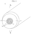
- Fig. 1 shows an end of a photonic crystal fiber 1 of an embodiment in accordance with the present invention.
- This photonic crystal fiber 1 is made from silica, plastic or the like, and includes a core 2 forming the center of the fiber, a cladding 3 which is provided to surround the core 2, and an outermost layer 4 which is provided to surround the cladding 3.
- the core 2 is solidly formed and may be doped with a functional substance such as germanium (Ge). A light signal is transmitted through this core 2 along its longitudinal direction.
- a functional substance such as germanium (Ge).
- the cladding 3 constitutes a porous part in which a plurality of microscopic holes 3a extending along the core 2 are formed.
- the plurality of microscopic holes 3a constitute a triangular grid in the cross-section of the fiber and are arranged to form a plurality of layers concentrically about the core 2, which forms a photonic crystal structure in the radial direction of the fiber.
- the light signal is confined within the core 2 by the cladding 3.
- Such a photonic crystal fiber 1 is fabricated as follows.
- a preform is prepared by filling a cylindrical support tube with a plurality of capillaries and a core member. At this time, the core member is adjusted to be placed on the central axis.
- the preform is set on a fiber-drawing machine, and then drawn at a high speed while being heated at a high temperature, thereby reducing its diameter (forming it into a fiber).
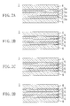
- a photonic crystal fiber thus fabricated has, as illustrated in Fig. 2A, an uneven end face.
- the microscopic holes 3a in the cladding 3 are first closed with blocking element 5 having a refractive index lower than the core 2 and a lower hardness than the fiber body.
- blocking element 5 having a refractive index lower than the core 2 and a lower hardness than the fiber body.
- the refractive index of pure silica is 1.452
- a substance to be used as the blocking element 5 has a lower refractive index than this value.
- the substance to be used as the blocking element 5 also has a lower hardness than this value.
- a portion of the outermost layer 4 located at the fiber end is polished into a tapered shape by the polishing machine.
- the photonic crystal fiber 1 fabricated in accordance with the aforementioned method is connected, as illustrated in Figs. 5 and 6, to an optical fiber 7 to be connected by butting the end face of the photonic crystal fiber 1 to the end face of the optical fiber within connectors 6 so as not to interpose any obstacles or an air layer therebetween.
- the openings of the microscopic holes 3a are closed with the blocking element 5 in advance before the fiber end face is polished.
- the polishing agent, the polishing dust or the like in the microscopic holes 3a deteriorates optical characteristics, and that the polishing agent, the polishing dust or the like coming out from the microscopic holes 3a interferes with light transmission by attaching to the core 2.
- the blocking element 5 closing the openings of the microscopic holes 3a has a lower refractive index than the core 2, it allows light to be transmitted in confinement within the core 2, and does not affect the optical characteristics of the photonic crystal fiber 1 in actually using it.
- the fiber end face is more easily ground away than the blocking element 5 during the polishing.
- the blocking element 5 may protrude beyond the fiber end face in connecting the photonic crystal fiber 1 and the optical fiber 7 to be connected, and the protruded blocking element 5 may prevent the end face of the photonic crystal fiber 1 and the end face of the optical fiber 7 to be connected from contacting each other.
- the blocking element 5 having a lower hardness than the fiber body, since, as illustrated in Fig. 3, the blocking element 5 is scraped into the microscopic holes 3a, the fiber end face can be perpendicular to the axial direction. Therefore, it is possible to contact and connect the end face of the photonic crystal fiber 1 and the end face of the optical fiber 7 to be connected so as not to interpose any obstacles or an air layer therebetween.
- the blocking element 5 relieves vibration and shock caused by the polishing, it is prevented that cracks and breakage occur in the cladding.
- the photonic crystal fiber in accordance with the present invention is suitably applicable to optical communication and the like.
Landscapes
- Physics & Mathematics (AREA)
- General Physics & Mathematics (AREA)
- Optics & Photonics (AREA)
- Engineering & Computer Science (AREA)
- Plasma & Fusion (AREA)
- Optical Fibers, Optical Fiber Cores, And Optical Fiber Bundles (AREA)
Applications Claiming Priority (3)
| Application Number | Priority Date | Filing Date | Title |
|---|---|---|---|
| JP2002160012A JP2004004320A (ja) | 2002-05-31 | 2002-05-31 | フォトニック結晶ファイバ及びその製造方法並びにフォトニック結晶ファイバの接続方法 |
| JP2002160012 | 2002-05-31 | ||
| PCT/JP2003/006904 WO2003102651A1 (fr) | 2002-05-31 | 2003-06-02 | Fibre de cristal photonique, son procede de fabrication et son procede de connexion |
Publications (2)
| Publication Number | Publication Date |
|---|---|
| EP1510841A1 true EP1510841A1 (fr) | 2005-03-02 |
| EP1510841A4 EP1510841A4 (fr) | 2005-06-15 |
Family
ID=29706531
Family Applications (1)
| Application Number | Title | Priority Date | Filing Date |
|---|---|---|---|
| EP03730745A Withdrawn EP1510841A4 (fr) | 2002-05-31 | 2003-06-02 | Fibre de cristal photonique, son procede de fabrication et son procede de connexion |
Country Status (6)
| Country | Link |
|---|---|
| US (1) | US20060062533A1 (fr) |
| EP (1) | EP1510841A4 (fr) |
| JP (1) | JP2004004320A (fr) |
| AU (1) | AU2003241718A1 (fr) |
| CA (1) | CA2487820A1 (fr) |
| WO (1) | WO2003102651A1 (fr) |
Cited By (1)
| Publication number | Priority date | Publication date | Assignee | Title |
|---|---|---|---|---|
| US7477821B2 (en) | 2004-10-25 | 2009-01-13 | Nagase Chemtex Corporation | Sealing composition and production method of optical fiber having air holes in the inside using the composition |
Families Citing this family (10)
| Publication number | Priority date | Publication date | Assignee | Title |
|---|---|---|---|---|
| JP3982515B2 (ja) | 2004-04-21 | 2007-09-26 | 住友電気工業株式会社 | 光結合構造 |
| JP2008287191A (ja) * | 2007-05-21 | 2008-11-27 | Hitachi Cable Ltd | 光ファイバ、光ファイバの端面封止方法、光ファイバの接続構造及び光コネクタ |
| JP4877067B2 (ja) * | 2007-05-22 | 2012-02-15 | 日立電線株式会社 | 光ファイバ、光ファイバの接続構造および光コネクタ |
| JP5117131B2 (ja) * | 2007-07-19 | 2013-01-09 | 古河電気工業株式会社 | ホーリーファイバおよびホーリーファイバの製造方法 |
| US7845860B2 (en) * | 2008-01-10 | 2010-12-07 | Hewlett-Packard Development Company, L.P. | Method for connecting multicore fibers to optical devices |
| JP5155987B2 (ja) | 2009-11-09 | 2013-03-06 | 日立電線株式会社 | 光ファイバの端部加工方法および光ファイバの端部加工装置 |
| JP5318834B2 (ja) | 2010-09-29 | 2013-10-16 | 日立電線株式会社 | 光ファイバ端部加工方法および光ファイバ端部加工装置 |
| JP5416721B2 (ja) | 2011-01-05 | 2014-02-12 | 日立金属株式会社 | 光ファイバ端部加工方法および光ファイバ端部加工装置 |
| US10101209B2 (en) | 2012-04-30 | 2018-10-16 | Finesse Solutions, Inc. | Method and apparatus for quantifying solutions comprised of multiple analytes |
| CN112362104B (zh) * | 2020-11-11 | 2022-07-22 | 重庆邮电大学 | 一种基于光子带隙的侧抛光纤-微结构光纤流体传感系统 |
Family Cites Families (6)
| Publication number | Priority date | Publication date | Assignee | Title |
|---|---|---|---|---|
| DE2542587A1 (de) * | 1975-09-24 | 1977-04-07 | Siemens Ag | Einmaterialfaser |
| US5802236A (en) * | 1997-02-14 | 1998-09-01 | Lucent Technologies Inc. | Article comprising a micro-structured optical fiber, and method of making such fiber |
| GB9929345D0 (en) * | 1999-12-10 | 2000-02-02 | Univ Bath | Improvements in and related to photonic-crystal fibres and photonic-crystal fibe devices |
| JP4329269B2 (ja) * | 2001-02-07 | 2009-09-09 | 住友電気工業株式会社 | 光ファイバの接続構造および光ファイバの接続方法 |
| JP3870713B2 (ja) * | 2001-04-25 | 2007-01-24 | 住友電気工業株式会社 | 光ファイバの端部構造および光ファイバ |
| US20030068150A1 (en) * | 2001-10-10 | 2003-04-10 | Rayteq Photonic Solutions Ltd. | Termination of end-faces of air-clad and photonic-crystal fibers |
-
2002
- 2002-05-31 JP JP2002160012A patent/JP2004004320A/ja active Pending
-
2003
- 2003-06-02 WO PCT/JP2003/006904 patent/WO2003102651A1/fr not_active Ceased
- 2003-06-02 AU AU2003241718A patent/AU2003241718A1/en not_active Abandoned
- 2003-06-02 US US10/512,641 patent/US20060062533A1/en not_active Abandoned
- 2003-06-02 CA CA002487820A patent/CA2487820A1/fr not_active Abandoned
- 2003-06-02 EP EP03730745A patent/EP1510841A4/fr not_active Withdrawn
Cited By (1)
| Publication number | Priority date | Publication date | Assignee | Title |
|---|---|---|---|---|
| US7477821B2 (en) | 2004-10-25 | 2009-01-13 | Nagase Chemtex Corporation | Sealing composition and production method of optical fiber having air holes in the inside using the composition |
Also Published As
| Publication number | Publication date |
|---|---|
| WO2003102651A1 (fr) | 2003-12-11 |
| EP1510841A4 (fr) | 2005-06-15 |
| CA2487820A1 (fr) | 2003-12-11 |
| AU2003241718A1 (en) | 2003-12-19 |
| JP2004004320A (ja) | 2004-01-08 |
| US20060062533A1 (en) | 2006-03-23 |
Similar Documents
| Publication | Publication Date | Title |
|---|---|---|
| US6652163B2 (en) | Splice joint and process for joining a microstructured optical fiber and a conventional optical fiber | |
| CN102257415B (zh) | 多芯光纤 | |
| EP2369376B1 (fr) | Fibre optique multinoyau | |
| CN103814312B (zh) | 通信用多芯光纤 | |
| CN106489087B (zh) | 多芯偏振保持光纤 | |
| EP1486804B1 (fr) | Fibre optique conservant la polarisation | |
| JP5409928B2 (ja) | 偏波保持光ファイバ | |
| JP5390741B2 (ja) | 光ファイバおよび光伝送媒体 | |
| EP1510841A1 (fr) | Fibre de cristal photonique, son procede de fabrication et son procede de connexion | |
| JP4974165B2 (ja) | 光ファイバの接続構造の製造方法 | |
| JP4329269B2 (ja) | 光ファイバの接続構造および光ファイバの接続方法 | |
| WO2010073822A1 (fr) | Fibre optique à coeur multiple | |
| CN103176246A (zh) | 包含连接器的多芯光纤 | |
| US7715674B2 (en) | Optical fiber and waveguide | |
| WO2005124409A1 (fr) | Procédé de connexion et structure de fibre de cristal photonique | |
| JP7529157B2 (ja) | 円筒多心フェルール及びその研磨方法 | |
| WO2006006604A1 (fr) | Fibre trouée de type assistance de trous et fibre trouee multimode a faible perte de torsion | |
| JP2006011328A (ja) | フォトニック結晶ファイバ | |
| US20240255709A1 (en) | Optical fiber bundle, optical connection structure, and method for manufacturing optical fiber bundle | |
| JP4823759B2 (ja) | 光ファイバ用コネクタ製造方法 | |
| JP3831315B2 (ja) | 光コネクタ | |
| JP4690249B2 (ja) | 高屈曲性光ファイバ | |
| JP4559458B2 (ja) | 光ファイバの製造方法 | |
| US12535642B2 (en) | Optical fiber bundle connector and method of manufacturing optical fiber bundle connector | |
| US20250155634A1 (en) | Optical fiber, optical device, and method for manufacturing optical device |
Legal Events
| Date | Code | Title | Description |
|---|---|---|---|
| PUAI | Public reference made under article 153(3) epc to a published international application that has entered the european phase |
Free format text: ORIGINAL CODE: 0009012 |
|
| 17P | Request for examination filed |
Effective date: 20041025 |
|
| AK | Designated contracting states |
Kind code of ref document: A1 Designated state(s): AT BE BG CH CY CZ DE DK EE ES FI FR GB GR HU IE IT LI LU MC NL PT RO SE SI SK TR |
|
| AX | Request for extension of the european patent |
Extension state: AL LT LV MK |
|
| A4 | Supplementary search report drawn up and despatched |
Effective date: 20050428 |
|
| RIC1 | Information provided on ipc code assigned before grant |
Ipc: 7G 02B 6/38 B Ipc: 7G 02B 6/255 B Ipc: 7G 02B 6/16 A |
|
| DAX | Request for extension of the european patent (deleted) | ||
| RBV | Designated contracting states (corrected) |
Designated state(s): DE FR GB |
|
| STAA | Information on the status of an ep patent application or granted ep patent |
Free format text: STATUS: THE APPLICATION IS DEEMED TO BE WITHDRAWN |
|
| 18D | Application deemed to be withdrawn |
Effective date: 20060412 |