EP1510867A1 - Appareil lithographique et méthode pour la fabrication d'un dispositif - Google Patents
Appareil lithographique et méthode pour la fabrication d'un dispositif Download PDFInfo
- Publication number
- EP1510867A1 EP1510867A1 EP03077701A EP03077701A EP1510867A1 EP 1510867 A1 EP1510867 A1 EP 1510867A1 EP 03077701 A EP03077701 A EP 03077701A EP 03077701 A EP03077701 A EP 03077701A EP 1510867 A1 EP1510867 A1 EP 1510867A1
- Authority
- EP
- European Patent Office
- Prior art keywords
- stage
- base
- projection apparatus
- gas
- lithographic projection
- Prior art date
- Legal status (The legal status is an assumption and is not a legal conclusion. Google has not performed a legal analysis and makes no representation as to the accuracy of the status listed.)
- Withdrawn
Links
Images

Classifications
-
- G—PHYSICS
- G03—PHOTOGRAPHY; CINEMATOGRAPHY; ANALOGOUS TECHNIQUES USING WAVES OTHER THAN OPTICAL WAVES; ELECTROGRAPHY; HOLOGRAPHY
- G03F—PHOTOMECHANICAL PRODUCTION OF TEXTURED OR PATTERNED SURFACES, e.g. FOR PRINTING, FOR PROCESSING OF SEMICONDUCTOR DEVICES; MATERIALS THEREFOR; ORIGINALS THEREFOR; APPARATUS SPECIALLY ADAPTED THEREFOR
- G03F7/00—Photomechanical, e.g. photolithographic, production of textured or patterned surfaces, e.g. printing surfaces; Materials therefor, e.g. comprising photoresists; Apparatus specially adapted therefor
- G03F7/70—Microphotolithographic exposure; Apparatus therefor
- G03F7/708—Construction of apparatus, e.g. environment aspects, hygiene aspects or materials
- G03F7/70908—Hygiene, e.g. preventing apparatus pollution, mitigating effect of pollution or removing pollutants from apparatus
- G03F7/70933—Purge, e.g. exchanging fluid or gas to remove pollutants
-
- G—PHYSICS
- G03—PHOTOGRAPHY; CINEMATOGRAPHY; ANALOGOUS TECHNIQUES USING WAVES OTHER THAN OPTICAL WAVES; ELECTROGRAPHY; HOLOGRAPHY
- G03F—PHOTOMECHANICAL PRODUCTION OF TEXTURED OR PATTERNED SURFACES, e.g. FOR PRINTING, FOR PROCESSING OF SEMICONDUCTOR DEVICES; MATERIALS THEREFOR; ORIGINALS THEREFOR; APPARATUS SPECIALLY ADAPTED THEREFOR
- G03F7/00—Photomechanical, e.g. photolithographic, production of textured or patterned surfaces, e.g. printing surfaces; Materials therefor, e.g. comprising photoresists; Apparatus specially adapted therefor
- G03F7/70—Microphotolithographic exposure; Apparatus therefor
- G03F7/70691—Handling of masks or workpieces
- G03F7/70716—Stages
-
- G—PHYSICS
- G03—PHOTOGRAPHY; CINEMATOGRAPHY; ANALOGOUS TECHNIQUES USING WAVES OTHER THAN OPTICAL WAVES; ELECTROGRAPHY; HOLOGRAPHY
- G03F—PHOTOMECHANICAL PRODUCTION OF TEXTURED OR PATTERNED SURFACES, e.g. FOR PRINTING, FOR PROCESSING OF SEMICONDUCTOR DEVICES; MATERIALS THEREFOR; ORIGINALS THEREFOR; APPARATUS SPECIALLY ADAPTED THEREFOR
- G03F7/00—Photomechanical, e.g. photolithographic, production of textured or patterned surfaces, e.g. printing surfaces; Materials therefor, e.g. comprising photoresists; Apparatus specially adapted therefor
- G03F7/70—Microphotolithographic exposure; Apparatus therefor
- G03F7/70691—Handling of masks or workpieces
- G03F7/70775—Position control, e.g. interferometers or encoders for determining the stage position
-
- G—PHYSICS
- G03—PHOTOGRAPHY; CINEMATOGRAPHY; ANALOGOUS TECHNIQUES USING WAVES OTHER THAN OPTICAL WAVES; ELECTROGRAPHY; HOLOGRAPHY
- G03F—PHOTOMECHANICAL PRODUCTION OF TEXTURED OR PATTERNED SURFACES, e.g. FOR PRINTING, FOR PROCESSING OF SEMICONDUCTOR DEVICES; MATERIALS THEREFOR; ORIGINALS THEREFOR; APPARATUS SPECIALLY ADAPTED THEREFOR
- G03F7/00—Photomechanical, e.g. photolithographic, production of textured or patterned surfaces, e.g. printing surfaces; Materials therefor, e.g. comprising photoresists; Apparatus specially adapted therefor
- G03F7/70—Microphotolithographic exposure; Apparatus therefor
- G03F7/708—Construction of apparatus, e.g. environment aspects, hygiene aspects or materials
- G03F7/7095—Materials, e.g. materials for housing, stage or other support having particular properties, e.g. weight, strength, conductivity, thermal expansion coefficient
Definitions
- the present invention relates to a lithographic projection apparatus comprising: a radiation system for providing a projection beam of radiation; a first support structure for supporting patterning means, the patterning means serving to pattern the projection beam according to a desired pattern; a second support structure for supporting a substrate; and a projection system for projecting the patterned beam onto a target portion of the substrate; at least one of said first and second support structures comprising a planar base; a movable stage for supporting said patterning means or said substrate, that can be moved over said planar base; and an actuator for providing said movement of said stage; a contactless position measuring device for performing a position measurement of said stage, and a first pump for generating a conditioned gas flow in a volume between said measuring device and said stage for improving said position measurement.
- a lithographic apparatus is a machine that applies a desired pattern onto a target portion of a substrate.
- Lithographic apparatus can be used, for example, in the manufacture of integrated circuits (ICs).
- a patterning means such as a mask, may be used to generate a circuit pattern corresponding to an individual layer of the IC, and this pattern can be imaged onto a target portion (e.g. comprising part of, one or several dies) on a substrate (e.g. a silicon wafer) that has a layer of radiation-sensitive material (resist).
- a single substrate will contain a network of adjacent target portions that are successively exposed.
- lithographic apparatus include so-called steppers, in which each target portion is irradiated by exposing an entire pattern onto the target portion in one go, and so-called scanners, in which each target portion is irradiated by scanning the pattern through the projection beam in a given direction (the "scanning"-direction) while synchronously scanning the substrate parallel or anti-parallel to this direction.
- the light source can be UV, DUV, EUV -light or an electron beam.
- a common problem is how to create a stable and conditioned environment for the position measuring devices that are used to locate and position the stage relative to the base.
- a contact-less measurement device is typically an interferometer, however, other devices such as optical or capacitive rulers (encoders) can also be applied.
- the stage is used for instance for holding a target substrate thereon; in order to illuminate the target substrate in synchronicity with a movable patterning means, the substrate is moved in a scan direction, and the precise positioning and alignment relative to the patterning means usually takes place in a closed loop control wherein the position of the stage is measured by interferometric measurement and adapted in response to said measurement.
- position measurement devices are used, that are very sensitive for variations of the media through which a position measurement is performed.
- a variation of the refractive index in said media is directly translated in a deviation of a measured position of the stage, therefore, it is very important that at all times the media, in particularly the media in the volume that is present between the measuring device and the movable stage, are kept stable.
- the media are kept at a stable and predictable variation of the refractive index, which is known to be sensitive to gas composition, pressure and temperature fluctuation. In general the variation is preferably kept at a near zero level.
- air shower In order to provide a stable media environment for letting a measurement beam pass through, a known concept is the so-called "air shower".
- This is a gas stream of a conditioned, in particular, thermo-conditioned, pressure regulated and/or purified gas (mixture), that is ejected in the path that a measurement beam travels in the measurement setup.
- air will be used to indicate gas media that are used in the environment of the base and stage.
- This gas media may be ambient air, possibly conditioned and purified.
- other gas media such as pure nitrogen may be included by this term and the invention is not restricted to air showers with ambient air.
- the invention has as one of its objects to provide a lithographic apparatus wherein these media environment conditions are further improved so that a more reliable positioning measurement can be performed.
- a lithographic apparatus is provided according to the features of claim 1.
- said gas channels are connected to a second pump for removing gas from said channels.
- Said stage may further be provided with a third pump, for removing gas from between said stage and said base.
- any of said pumps are arranged to provide a gas flow speed that between said stage and said base that is higher than the maximum speed of the stage on said base.
- said gas channels in said base are provided with valves arranged to close due to suction of said third pump.
- Such an arrangement is convenient for developing a vacuum pressure between the stage and the base, for instance, in a so called "air foot” configuration which will be described later.
- said gas channels are preferably provided in a regular pattern across substantially the whole planar base.
- Such a regular pattern preferably has a fine pitch. In this way, the flow path of the air shower is optimally independent of a relative position of the stage on said base.
- any of said pumps may be so connected as to provide a closed-loop air shower.
- This embodiment provides the benefit that the air is already preconditioned before use, so that the load for cooling and purification devices is reduced.
- said base and said stage are contained in a closed environment, and wherein cooling and/or purifying devices are coupled between any of said pumps.
- the gas flow is preferably oriented perpendicular to said base.
- Said measuring device is preferably an interferometer providing a measuring beam parallel to said base. In this way, the air shower is optimally unaffected by the movement of the stage.
- the invention is especially beneficial in an arrangement, wherein said actuator comprises a planar electro magnetic motor.
- said actuator comprises a planar electro magnetic motor.
- Such an arrangement offers an advantage of an improved position accuracy of the control of the planar movements of the stage, in particular, the possibility to provide a stage movement with up to six degrees of freedom.
- such actuator arrangements produce a significant amount of heat due to the energy generated in the electric wiring. This heat can affect the reliability of the measuring devices, that are used for providing position information of the stage, which may result in a loss of imaging resolution.
- said planar magnetic motor comprises a stator coupled to said base; and a translator movable relative to said stator and coupled to said stage in order to provide a movement of the stage by electromagnetic forces wherein at least one of said stator and said translator comprises a grid of magnets and/or electric wiring wherein said gas channels are provided on preselected corners of said grid.
- said stage may be provided with a further pump in order to provide an air bearing between said stage and said base.
- a further pump in order to provide an air bearing between said stage and said base.
- Such an arrangement is also known as an "air foot”, enabling an in plane bearing with 3 degrees of freedom (3DoF).
- Such a bearing can be with or without a planar magnet motor arrangement as here above described.
- lithographic apparatus in the manufacture of ICs, it should be understood that the lithographic apparatus described herein may have other applications, such as the manufacture of integrated optical systems, guidance and detection patterns for magnetic domain memories, liquid-crystal displays (LCDs), thin-film magnetic heads, etc.
- LCDs liquid-crystal displays
- any use of the terms “wafer” or “die” herein may be considered as synonymous with the more general terms “substrate” or "target portion”, respectively.
- the substrate referred to herein may be processed, before or after exposure, in for example a track (a tool that typically applies a layer of resist to a substrate and develops the exposed resist) or a metrology or inspection tool.
- the disclosure herein may be applied to such and other substrate processing tools.
- the substrate may be processed more than once, for example in order to create a multi-layer IC, so that the term substrate used herein may also refer to a substrate that already contains multiple processed layers.
- UV radiation e.g. having a wavelength of 365, 248, 193, 157 or 126 nm
- EUV extreme ultra-violet
- particle beams such as ion beams or electron beams.
- patterning means used herein should be broadly interpreted as referring to means that can be used to impart a projection beam with a pattern in its cross-section such as to create a pattern in a target portion of the substrate. It should be noted that the pattern imparted to the projection beam may not exactly correspond to the desired pattern in the target portion of the substrate. Generally, the pattern imparted to the projection beam will correspond to a particular functional layer in a device being created in the target portion, such as an integrated circuit.
- Patterning means may be transmissive or reflective.
- Examples of patterning means include masks, programmable mirror arrays, and programmable LCD panels.
- Masks are well known in lithography, and include mask types such as binary, alternating phase-shift, and attenuated phase-shift, as well as various hybrid mask types.
- An example of a programmable mirror array employs a matrix arrangement of small mirrors, each of which can be individually tilted so as to reflect an incoming radiation beam in different directions; in this manner, the reflected beam is patterned.
- the support structure may be a frame or table, for example, which may be fixed or movable as required and which may ensure that the patterning means is at a desired position, for example with respect to the projection system. Any use of the terms "reticle” or “mask” herein may be considered synonymous with the more general term "patterning means”.
- projection system used herein should be broadly interpreted as encompassing various types of projection system, including refractive optical systems, reflective optical systems, and catadioptric optical systems, as appropriate for example for the exposure radiation being used, or for other factors such as the use of an immersion fluid or the use of a vacuum. Any use of the term “lens” herein may be considered as synonymous with the more general term “projection system”.
- the illumination system may also encompass various types of optical components, including refractive, reflective, and catadioptric optical components for directing, shaping, or controlling the projection beam of radiation, and such components may also be referred to below, collectively or singularly, as a "lens”.
- the lithographic apparatus may be of a type having two (dual stage) or more substrate tables (and/or two or more mask tables). In such "multiple stage” machines the additional tables may be used in parallel, or preparatory steps may be carried out on one or more tables while one or more other tables are being used for exposure.
- the lithographic apparatus may also be of a type wherein the substrate is immersed in a liquid having a relatively high refractive index, e.g. water, so as to fill a space between the final element of the projection system and the substrate.
- Immersion liquids may also be applied to other spaces in the lithographic apparatus, for example, between the mask and the first element of the projection system. Immersion techniques are well known in the art for increasing the numerical aperture of projection systems.
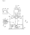
- Figure 1 schematically depicts a lithographic apparatus according to a particular embodiment of the invention.
- the apparatus comprises:
- the apparatus is of a transmissive type (e.g. employing a transmissive mask).
- the apparatus may be of a reflective type (e.g. employing a programmable mirror array of a type as referred to above).
- the illuminator IL receives a beam of radiation from a radiation source SO.
- the source and the lithographic apparatus may be separate entities, for example when the source is an excimer laser. In such cases, the source is not considered to form part of the lithographic apparatus and the radiation beam is passed from the source SO to the illuminator IL with the aid of a beam delivery system BD comprising for example suitable directing mirrors and/or a beam expander. In other cases the source may be integral part of the apparatus, for example when the source is a mercury lamp.
- the source SO and the illuminator IL, together with the beam delivery system BD if required, may be referred to as a radiation system.
- the illuminator IL may comprise adjusting means AM for adjusting the angular intensity distribution of the beam.
- adjusting means AM for adjusting the angular intensity distribution of the beam.
- the illuminator IL generally comprises various other components, such as an integrator IN and a condenser CO.
- the illuminator provides a conditioned beam of radiation, referred to as the projection beam PB, having a desired uniformity and intensity distribution in its cross-section.
- the projection beam PB is incident on the mask MA, which is held on the mask table MT. Having traversed the mask MA, the projection beam PB passes through the lens PL, which focuses the beam onto a target portion C of the substrate W.
- the substrate table WT can be moved accurately, e.g. so as to position different target portions C in the path of the beam PB.
- the first positioning means PM and another position sensor can be used to accurately position the mask MA with respect to the path of the beam PB, e.g. after mechanical retrieval from a mask library, or during a scan.
- the mask table MT may be connected to a short stroke actuator only, or may be fixed.
- Mask MA and substrate W may be aligned using mask alignment marks M1, M2 and substrate alignment marks P1, P2.
- a schematic face view is illustrated of a support structure 1, for supporting for instance a wafer (not illustrated).
- the structure 1 comprises a planar base 2 and a movable stage 3 that can be moved over said planar base 2 in at least three DoF.
- a the movable stage 3 comprises a lower part 5 and an upper part 6.
- These parts 5 and 6 are usually actuated by different actuators; in particular, the lower part 5 is actuated by a coarse positioning device (not shown) and the upper part 6 is actuated by a fine positioning device (not shown).
- the measurement device is a interferometer that projects an interferometric measurement beam 4 onto the upper part, so that precise positioning information of the upper part 6 of the stage 3 can be obtained of typically a (sub)nanometer resolution. Since a wafer has a fixed positional relationship to this upper part 6 of the stage 3, the lithographic imaging can be performed at a very high resolution.
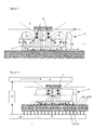
- Figure 2 and Figure 3 is illustrated a conventional air shower setup and an air shower setup according to the invention, respectively.
- a schematic gas flow 7 is illustrated of gas that is ejected from a pump 8, seen along the direction of the measurement beam 4.
- the pump 8 projects the gas flow into the path of the measurement beam 4.
- the gas flow 7 (generally referenced as "air shower") crosses the measurement beam 4 perpendicular and thereby creates a stable media environment for the measurement to travel through.
- the media is kept at a relative constant composition, pressure and temperature; resulting a substantially constant refractive index. Since the refractive index of the media is substantially constant, a reliable position indication can be obtained; whereas a variation of the refractive index would have a direct consequence of the measured position.
- the air shower 7 generated by the pump 8 is not able to create a stable media environment for the measurement beam 4, since the presence of the base 2, in addition to a movement of the stage 3 creates turbulence (indicated in the vicinity of arrow 9) of the gas flow of the air shower 7.
- This turbulence 9 is detrimental for the requirement of a stable media environment for the measurement beam 4 to travel through, which may result in an inferior image resolution of the lithographic process.
- Figure 3 shows an improved air shower 7 setup according to the invention.
- the base 2 is provided with gas channels 10 (for clarity reasons, only a few of which are referenced in the figure), in order to provide a flow path for said air shower 7 through said base 2.
- the gas channels 10 are in connection with an air pump 11, for creating a suction force to guide the flow path of air shower 7 through the gas channels 10.
- the gas channels 10 provide a flow path for the air shower 7 through the base 2, thus minimizing turbulence through bouncing back of air streams that "bounce" on the base 2.
- a closed-loop air shower arrangement is illustrated, where the air pump 11 is connected via a cooling/and or purifying device 12 between said pump 11 and said pump 8. In this way, the air is already preconditioned before use, so that the load for cooling and purification device 12 is reduced.
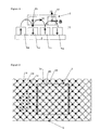
- FIG. 1 shows a schematic view of a magnetic planar motor 13.
- a motor 13 is able to actuate (in 3 DoF or 6 DoF) the stage 3 in a plane generally parallel to the planar base 2 over which the stage 3 moves.
- the base 2 is covered by a matrix of magnet elements 14.
- These can be electromagnetic coils, or, such as is depicted in Figure 4, permanent magnets having an alternating pole orientation, thus providing a checkerboard pattern.
- the magnetic flux lines (indicated by arrows reference by letter B and curved arrows) of the magnets 14 provide a magnetic field wherein a current conductor senses an electromagnetic force.
- two current conducting wires 15 (wherein the shown current flows towards the viewer in a direction perpendicular to the plane of view) spaced apart having a spacing equal to the core-core distance of the magnets 14, can provide an inplane force in a first direction (referenced by arrow P) and a lifting force (referenced by arrow Q) for lifting the stage 3 from said base 2.
- the shown wires 15 have (not shown) cross-oriented counterparts for providing an additional force in a direction orthogonal to the said first direction, as well as an additional lifting force.
- a wiring arrangement is provided in said stage 3 to provide a (3 DoF up to 6 DoF) movement of said stage 3 by electromagnetic forces.
- Figure 5 shows a partial plane view of the base 2 for the magnetic planar motor as described with reference to Figure 4.
- the base 2 is covered with a diagonally oriented checkerboard pattern of magnets 14 having alternating poles (schematically indicated by "N" for North pole and "S" for South pole on selected positions).
- magnets 14 having alternating poles (schematically indicated by "N" for North pole and "S" for South pole on selected positions).
- gas channels 10 are provided of about 2 - 5 mm diameter.
- base 2 about 100 - 1000 gas channels are present, where in Figure 5, the stage 3 is schematically illustrated.
- the gas channels 10 that are covered by the stage 3 are greyed.
- the flow resistance of the gas channels 10 an the suction pressure of the pump 11 are so arranged that the gas flow speed between the stage 3 and the base 2 is higher than the maximum speed of the stage on said base, the scan speed being normally in the order of 0.1 up to 2 m/s.
- the maximum speed is preferably not higher than 20 m/s in order to prevent turbulence due to the high flow velocity (whistle).
- a low vacuum (100-5000 [Pa]) pressure can be applied.
- approx. 90 % of all supplied air may be removed via gas channels in the base 2 at an extraction flow of 1000 [m3/hr].
- the inventive air shower is much less sensitive for collisions, turbulence and shear off of heated air.
- the top down air-flow will better maintain its laminar character, because there is no collision and bouncing back with floor.
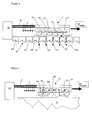
- FIG. 6 shows a first schematic embodiment according to the invention for a lithographic apparatus comprising a planar magnetic motor.
- a movable stage 3 is actuated via coils 16 that are provided in the stage 3.
- the coils 16 comprise a wiring arrangement as discussed with reference to Figure 4, so as to provide a stage that is movable in a plane parallel to the base 2. Since a plurality of coils 16 can be controlled independent of each other, apart from a movement in plane and a movement out of the plane, also tilting movements of the stage 3 can be provided, thus offering six degrees of freedom.
- These coils 16 produce a heat load in the order of several kW, which results in a temperature of several tens of degrees higher than the target temperature of the media environment of the measurement beam, even after cooling by a channel system of water cooling ducts 17 that are provided in the stage 3.
- a heat production may be in the order of 1-4 kW, which gives rise to a stage temperature of 50 °C near the surface 18 of the stage 3 facing the base 2. Consequently, the air may heat up significantly above a target temperature of 22 °C.
- the heated air is trapped between the surface 18 and the base 2 and does not contaminate the stable media environment for the interferometric measurement beam 4 originating from and reflecting towards the interferometer 19 that is part of a projection optics frame (not shown).
- Figure 7 shows an alternative embodiment for a planar magnetic motor configuration having a planar base 2 provided with a matrix arrangement of magnets (not shown); a stage 3 movable with respect to said base 2 and being provided with an electric coil 16 arrangement in order to provide a movement of said stage 3 by electromagnetic forces.
- the stage 3 is provided with a pump 20, for removing heated air from between said stage and said base.
- the pump 20 may comprise a pump that is located on stage 3, or a pump that is located at place remote from the stage and connect through flexible hosing (not shown).
- Figure 7 is illustrated without gas channels present in the magnetic plate, the skilled person will understand that an embodiment where these gas channels are present in addition to the shown exhaust of the stage equally falls within the scope of the invention.
- the flow speed of the exhaust is chosen so as to confine the heated air under between the stage 3 and base 2, so that the media environment for the interferometric measurement beam 4 is kept at a stable temperature.
- Figure 8 shows an embodiment of the invention for a different type of actuator than the previously illustrated magnetic planar motor embodiments.
- the actuator illustrated in the embodiment of Figure 8 uses a "conventional" air foot construction with 3 DoF in plane (Z-Rx,Ry)direction bearing and 3 DoF (X,Y,Rz direction) actuation, provided with the advantageous gas channels 10 provided in the base 2 as explained hereabove.
- an "air foot” in order to provide a stable support structure for the stage 3 uses a second pump 21 for removing gas from between said stage and said base. In the embodiment of Figure 8 this creates a local vacuum pressure that clamps the stage to the base and thus keeps it substantially in a plane parallel to said base.
- valves 22 e.g. ball valves, that only permit one-way circulation of gas flow.
- the valves are connected to a flow path that flows to a pump such as a suction pump 11 or the like.
- the air foot configuration comprises a pump 23 in order to provide an air bearing between said stage 3 and said base 2.
- the suction pressure of the second pump 21, the suction pressure of the pump 11, the air pressure generated by the pump 23 and the flow resistance of the opening gas channels and the space between the stage 3 and base 2 are balanced in a way that the air foot is born by the air bearing provided by pump 23 and clamped by suction pump 21, while the valves are shut closed when the stage 3 is above the gas channels 10.
- block in Figure 8.
- the flow path of the air is guided through the gas channels 10 provided in the base, which is schematically indicated by the term "open" in Figure 8.
- the movable stage is a stage for holding a substrate in the photolithographic apparatus
- the contactless measuring devices are illustrated in the form of interferometric measurement devices.
- other type of contactless measurement devices such as capacitive sensors, optical level sensors, stage and wafer alignment sensors and optical image sensors could benefit from the invention and as such fall within the scope of the appended claims.
- the term "pump" is used for any air stream generating structure that is able to create a gas flow. In this context, the any pump may used to either propel or suck said gas flow, depending on a particular flow path desired. In particular, the flow paths illustrated may be reversed equally without falling out the scope of the claims.
Landscapes
- Physics & Mathematics (AREA)
- General Physics & Mathematics (AREA)
- Health & Medical Sciences (AREA)
- Epidemiology (AREA)
- Public Health (AREA)
- Engineering & Computer Science (AREA)
- Environmental & Geological Engineering (AREA)
- Life Sciences & Earth Sciences (AREA)
- Atmospheric Sciences (AREA)
- Exposure And Positioning Against Photoresist Photosensitive Materials (AREA)
- Exposure Of Semiconductors, Excluding Electron Or Ion Beam Exposure (AREA)
Priority Applications (4)
| Application Number | Priority Date | Filing Date | Title |
|---|---|---|---|
| EP03077701A EP1510867A1 (fr) | 2003-08-29 | 2003-08-29 | Appareil lithographique et méthode pour la fabrication d'un dispositif |
| US10/925,148 US7359032B2 (en) | 2003-08-29 | 2004-08-25 | Lithographic apparatus and device manufacturing method |
| JP2004247637A JP4157511B2 (ja) | 2003-08-29 | 2004-08-27 | リソグラフィ機器及びデバイスの製造方法 |
| US12/068,071 US7679720B2 (en) | 2003-08-29 | 2008-02-01 | Apparatus configured to position a workpiece |
Applications Claiming Priority (1)
| Application Number | Priority Date | Filing Date | Title |
|---|---|---|---|
| EP03077701A EP1510867A1 (fr) | 2003-08-29 | 2003-08-29 | Appareil lithographique et méthode pour la fabrication d'un dispositif |
Publications (1)
| Publication Number | Publication Date |
|---|---|
| EP1510867A1 true EP1510867A1 (fr) | 2005-03-02 |
Family
ID=34089671
Family Applications (1)
| Application Number | Title | Priority Date | Filing Date |
|---|---|---|---|
| EP03077701A Withdrawn EP1510867A1 (fr) | 2003-08-29 | 2003-08-29 | Appareil lithographique et méthode pour la fabrication d'un dispositif |
Country Status (3)
| Country | Link |
|---|---|
| US (2) | US7359032B2 (fr) |
| EP (1) | EP1510867A1 (fr) |
| JP (1) | JP4157511B2 (fr) |
Cited By (2)
| Publication number | Priority date | Publication date | Assignee | Title |
|---|---|---|---|---|
| CN103904804A (zh) * | 2012-12-28 | 2014-07-02 | 上海微电子装备有限公司 | 用于电机绕组的线圈单元及应用该线圈单元的平面电机 |
| CN118808925A (zh) * | 2024-08-27 | 2024-10-22 | 惠州市美森源红木业科技有限公司 | 一种装饰板表面加工用激光刻字装置 |
Families Citing this family (24)
| Publication number | Priority date | Publication date | Assignee | Title |
|---|---|---|---|---|
| EP1510867A1 (fr) * | 2003-08-29 | 2005-03-02 | ASML Netherlands B.V. | Appareil lithographique et méthode pour la fabrication d'un dispositif |
| JP4614386B2 (ja) * | 2005-02-04 | 2011-01-19 | キヤノン株式会社 | 位置決め装置、露光装置およびそれを用いたデバイス製造方法 |
| JP2006287160A (ja) * | 2005-04-05 | 2006-10-19 | Nikon Corp | 露光装置及びデバイスの製造方法 |
| US7432513B2 (en) * | 2005-10-21 | 2008-10-07 | Asml Netherlands B.V. | Gas shower, lithographic apparatus and use of a gas shower |
| US7542127B2 (en) * | 2005-12-21 | 2009-06-02 | Asml Netherlands B.V. | Lithographic apparatus and method for manufacturing a device |
| JP4702083B2 (ja) * | 2006-02-10 | 2011-06-15 | ウシオ電機株式会社 | XYθ移動ステージ |
| US7253875B1 (en) * | 2006-03-03 | 2007-08-07 | Asml Netherlands B.V. | Lithographic apparatus and device manufacturing method |
| CN100552877C (zh) * | 2006-05-04 | 2009-10-21 | 台湾积体电路制造股份有限公司 | 蚀刻装置、浸润槽及蚀刻方法 |
| US7675604B2 (en) * | 2006-05-04 | 2010-03-09 | Taiwan Semiconductor Manufacturing Company, Ltd. | Hood for immersion lithography |
| US7567339B2 (en) * | 2006-09-08 | 2009-07-28 | Asml Netherlands B.V. | Lithographic apparatus with gas bearing supply mechanism and device manufacturing method |
| US8264662B2 (en) | 2007-06-18 | 2012-09-11 | Taiwan Semiconductor Manufacturing Company, Ltd. | In-line particle detection for immersion lithography |
| US8283813B2 (en) | 2007-06-27 | 2012-10-09 | Brooks Automation, Inc. | Robot drive with magnetic spindle bearings |
| US8823294B2 (en) | 2007-06-27 | 2014-09-02 | Brooks Automation, Inc. | Commutation of an electromagnetic propulsion and guidance system |
| CN101855811B (zh) | 2007-06-27 | 2013-11-20 | 布鲁克斯自动化公司 | 具有提升能力和减少的齿槽特性的电机定子 |
| CN101790673B (zh) * | 2007-06-27 | 2013-08-28 | 布鲁克斯自动化公司 | 用于自轴承电机的位置反馈 |
| US9752615B2 (en) * | 2007-06-27 | 2017-09-05 | Brooks Automation, Inc. | Reduced-complexity self-bearing brushless DC motor |
| KR101659931B1 (ko) | 2007-06-27 | 2016-09-26 | 브룩스 오토메이션 인코퍼레이티드 | 다차원 위치 센서 |
| KR20100056468A (ko) | 2007-07-17 | 2010-05-27 | 브룩스 오토메이션 인코퍼레이티드 | 챔버 벽들에 일체화된 모터들을 갖는 기판 처리 장치 |
| US7667355B2 (en) * | 2008-01-04 | 2010-02-23 | Asm Assembly Automation Ltd. | Apparatus for generating amplified cooling air flows |
| JP2010238986A (ja) * | 2009-03-31 | 2010-10-21 | Nikon Corp | 露光装置及びデバイスの製造方法 |
| US9864279B2 (en) | 2010-08-05 | 2018-01-09 | Asml Netherlands B.V. | Imprint lithography |
| TWI511230B (zh) * | 2012-01-04 | 2015-12-01 | Chroma Ate Inc | A detection machine with a mask |
| WO2016074876A1 (fr) * | 2014-11-13 | 2016-05-19 | Asml Netherlands B.V. | Appareil lithographique et procédé de fabrication de dispositif |
| US10670959B2 (en) * | 2017-05-10 | 2020-06-02 | Taiwan Semiconductor Manufacturing Company, Ltd. | Pellicle and method of using the same |
Citations (6)
| Publication number | Priority date | Publication date | Assignee | Title |
|---|---|---|---|---|
| EP0242178A2 (fr) * | 1986-04-15 | 1987-10-21 | Hampshire Instruments, Inc | Générateur de faisceau laser pour utilisation avec un dispositif de lithographie à rayons-X |
| WO2001084241A1 (fr) * | 2000-05-03 | 2001-11-08 | Silicon Valley Group, Inc. | Joint sans contact a purge gazeuse |
| US20020045113A1 (en) * | 2000-07-14 | 2002-04-18 | Pril Wouter Onno | Lithographic projection apparatus, device manufacturing method, device manufactured thereby and gas composition |
| US6445093B1 (en) * | 2000-06-26 | 2002-09-03 | Nikon Corporation | Planar motor with linear coil arrays |
| EP1243972A1 (fr) * | 2001-03-20 | 2002-09-25 | ASML Netherlands B.V. | Système de positionnement et appareil de projection lithographique |
| US6542220B1 (en) * | 1999-11-05 | 2003-04-01 | Asml Netherlands, B.V. | Purge gas systems for use in lithographic projection apparatus |
Family Cites Families (11)
| Publication number | Priority date | Publication date | Assignee | Title |
|---|---|---|---|---|
| US5528118A (en) * | 1994-04-01 | 1996-06-18 | Nikon Precision, Inc. | Guideless stage with isolated reaction stage |
| JP3695000B2 (ja) * | 1996-08-08 | 2005-09-14 | 株式会社ニコン | 露光方法及び露光装置 |
| JP3372782B2 (ja) * | 1996-10-04 | 2003-02-04 | キヤノン株式会社 | 走査ステージ装置および走査型露光装置 |
| JPH10209040A (ja) | 1996-11-25 | 1998-08-07 | Nikon Corp | 露光装置 |
| JPH10256356A (ja) | 1997-03-17 | 1998-09-25 | Nikon Corp | 位置決め装置及び該装置を備えた露光装置 |
| JP3013837B2 (ja) | 1998-04-27 | 2000-02-28 | 日本電気株式会社 | ステージ位置計測装置およびその計測方法 |
| US5997963A (en) * | 1998-05-05 | 1999-12-07 | Ultratech Stepper, Inc. | Microchamber |
| US6114781A (en) * | 1999-02-26 | 2000-09-05 | Nikon Corporation | Cooling system for a linear or planar motor |
| US6528907B2 (en) * | 2000-04-07 | 2003-03-04 | Mirae Corporation | Linear motor |
| JP4236252B2 (ja) * | 2003-05-06 | 2009-03-11 | キヤノン株式会社 | ステージ装置及び露光装置 |
| EP1510867A1 (fr) * | 2003-08-29 | 2005-03-02 | ASML Netherlands B.V. | Appareil lithographique et méthode pour la fabrication d'un dispositif |
-
2003
- 2003-08-29 EP EP03077701A patent/EP1510867A1/fr not_active Withdrawn
-
2004
- 2004-08-25 US US10/925,148 patent/US7359032B2/en not_active Expired - Lifetime
- 2004-08-27 JP JP2004247637A patent/JP4157511B2/ja not_active Expired - Fee Related
-
2008
- 2008-02-01 US US12/068,071 patent/US7679720B2/en not_active Expired - Lifetime
Patent Citations (6)
| Publication number | Priority date | Publication date | Assignee | Title |
|---|---|---|---|---|
| EP0242178A2 (fr) * | 1986-04-15 | 1987-10-21 | Hampshire Instruments, Inc | Générateur de faisceau laser pour utilisation avec un dispositif de lithographie à rayons-X |
| US6542220B1 (en) * | 1999-11-05 | 2003-04-01 | Asml Netherlands, B.V. | Purge gas systems for use in lithographic projection apparatus |
| WO2001084241A1 (fr) * | 2000-05-03 | 2001-11-08 | Silicon Valley Group, Inc. | Joint sans contact a purge gazeuse |
| US6445093B1 (en) * | 2000-06-26 | 2002-09-03 | Nikon Corporation | Planar motor with linear coil arrays |
| US20020045113A1 (en) * | 2000-07-14 | 2002-04-18 | Pril Wouter Onno | Lithographic projection apparatus, device manufacturing method, device manufactured thereby and gas composition |
| EP1243972A1 (fr) * | 2001-03-20 | 2002-09-25 | ASML Netherlands B.V. | Système de positionnement et appareil de projection lithographique |
Cited By (2)
| Publication number | Priority date | Publication date | Assignee | Title |
|---|---|---|---|---|
| CN103904804A (zh) * | 2012-12-28 | 2014-07-02 | 上海微电子装备有限公司 | 用于电机绕组的线圈单元及应用该线圈单元的平面电机 |
| CN118808925A (zh) * | 2024-08-27 | 2024-10-22 | 惠州市美森源红木业科技有限公司 | 一种装饰板表面加工用激光刻字装置 |
Also Published As
| Publication number | Publication date |
|---|---|
| JP4157511B2 (ja) | 2008-10-01 |
| JP2005079585A (ja) | 2005-03-24 |
| US7359032B2 (en) | 2008-04-15 |
| US20050083496A1 (en) | 2005-04-21 |
| US20080174750A1 (en) | 2008-07-24 |
| US7679720B2 (en) | 2010-03-16 |
Similar Documents
| Publication | Publication Date | Title |
|---|---|---|
| US7679720B2 (en) | Apparatus configured to position a workpiece | |
| US7379159B2 (en) | Lithographic apparatus and device manufacturing method | |
| US7253875B1 (en) | Lithographic apparatus and device manufacturing method | |
| JP4410216B2 (ja) | 2ステージ・リソグラフィ装置及びデバイス製造方法 | |
| KR100902644B1 (ko) | 평면 모터 구동 지지체를 갖는 리소그래피 장치 | |
| US20050132914A1 (en) | Lithographic apparatus, alignment apparatus, device manufacturing method, and a method of converting an apparatus | |
| US7205741B2 (en) | Planar motor initialization method, planar motor, lithographic apparatus and device manufacturing method | |
| US7541699B2 (en) | Magnet assembly, linear actuator, planar motor and lithographic apparatus | |
| KR20010082053A (ko) | 온도 제어된 열 차폐부를 구비한 전사투영장치 | |
| US7167234B2 (en) | Actuator assembly and lithographic apparatus comprising such an actuator assembly | |
| US7259832B2 (en) | Lithographic apparatus and device manufacturing method | |
| US20080067967A1 (en) | Stage apparatus and lithographic apparatus | |
| JP5456848B2 (ja) | リソグラフィ装置及びデバイス製造方法 | |
| US7420299B2 (en) | Lithographic apparatus and device manufacturing method | |
| US7456527B2 (en) | Moveable object carrier, lithographic apparatus comprising the moveable object carrier and device manufacturing method | |
| US8264664B2 (en) | Method for producing a marker on a substrate, lithographic apparatus and device manufacturing method | |
| US9852937B2 (en) | Object table, lithographic apparatus and device manufacturing method | |
| US7978307B2 (en) | Gas bearing, and lithographic apparatus provided with such a bearing | |
| US7592760B2 (en) | Lithographic apparatus and device manufacturing method | |
| US20190074756A1 (en) | Magnet array, electric coil device, displacement system, lithographic apparatus and device manufacturing method |
Legal Events
| Date | Code | Title | Description |
|---|---|---|---|
| PUAI | Public reference made under article 153(3) epc to a published international application that has entered the european phase |
Free format text: ORIGINAL CODE: 0009012 |
|
| AK | Designated contracting states |
Kind code of ref document: A1 Designated state(s): AT BE BG CH CY CZ DE DK EE ES FI FR GB GR HU IE IT LI LU MC NL PT RO SE SI SK TR |
|
| AX | Request for extension of the european patent |
Extension state: AL LT LV MK |
|
| AKX | Designation fees paid | ||
| REG | Reference to a national code |
Ref country code: DE Ref legal event code: 8566 |
|
| STAA | Information on the status of an ep patent application or granted ep patent |
Free format text: STATUS: THE APPLICATION IS DEEMED TO BE WITHDRAWN |
|
| 18D | Application deemed to be withdrawn |
Effective date: 20050902 |