EP1511024A2 - Korrekturplatte der sphärischen Aberration - Google Patents
Korrekturplatte der sphärischen Aberration Download PDFInfo
- Publication number
- EP1511024A2 EP1511024A2 EP04253763A EP04253763A EP1511024A2 EP 1511024 A2 EP1511024 A2 EP 1511024A2 EP 04253763 A EP04253763 A EP 04253763A EP 04253763 A EP04253763 A EP 04253763A EP 1511024 A2 EP1511024 A2 EP 1511024A2
- Authority
- EP
- European Patent Office
- Prior art keywords
- spherical aberration
- wedge
- disc
- aberration corrector
- thickness
- Prior art date
- Legal status (The legal status is an assumption and is not a legal conclusion. Google has not performed a legal analysis and makes no representation as to the accuracy of the status listed.)
- Withdrawn
Links
Images



Classifications
-
- G—PHYSICS
- G11—INFORMATION STORAGE
- G11B—INFORMATION STORAGE BASED ON RELATIVE MOVEMENT BETWEEN RECORD CARRIER AND TRANSDUCER
- G11B7/00—Recording or reproducing by optical means, e.g. recording using a thermal beam of optical radiation by modifying optical properties or the physical structure, reproducing using an optical beam at lower power by sensing optical properties; Record carriers therefor
- G11B7/12—Heads, e.g. forming of the optical beam spot or modulation of the optical beam
- G11B7/135—Means for guiding the beam from the source to the record carrier or from the record carrier to the detector
- G11B7/1365—Separate or integrated refractive elements, e.g. wave plates
- G11B7/1369—Active plates, e.g. liquid crystal panels or electrostrictive elements
-
- G—PHYSICS
- G11—INFORMATION STORAGE
- G11B—INFORMATION STORAGE BASED ON RELATIVE MOVEMENT BETWEEN RECORD CARRIER AND TRANSDUCER
- G11B7/00—Recording or reproducing by optical means, e.g. recording using a thermal beam of optical radiation by modifying optical properties or the physical structure, reproducing using an optical beam at lower power by sensing optical properties; Record carriers therefor
- G11B7/12—Heads, e.g. forming of the optical beam spot or modulation of the optical beam
- G11B7/135—Means for guiding the beam from the source to the record carrier or from the record carrier to the detector
- G11B7/1365—Separate or integrated refractive elements, e.g. wave plates
-
- G—PHYSICS
- G11—INFORMATION STORAGE
- G11B—INFORMATION STORAGE BASED ON RELATIVE MOVEMENT BETWEEN RECORD CARRIER AND TRANSDUCER
- G11B7/00—Recording or reproducing by optical means, e.g. recording using a thermal beam of optical radiation by modifying optical properties or the physical structure, reproducing using an optical beam at lower power by sensing optical properties; Record carriers therefor
- G11B7/12—Heads, e.g. forming of the optical beam spot or modulation of the optical beam
- G11B7/135—Means for guiding the beam from the source to the record carrier or from the record carrier to the detector
- G11B7/1392—Means for controlling the beam wavefront, e.g. for correction of aberration
- G11B7/13925—Means for controlling the beam wavefront, e.g. for correction of aberration active, e.g. controlled by electrical or mechanical means
-
- G—PHYSICS
- G11—INFORMATION STORAGE
- G11B—INFORMATION STORAGE BASED ON RELATIVE MOVEMENT BETWEEN RECORD CARRIER AND TRANSDUCER
- G11B7/00—Recording or reproducing by optical means, e.g. recording using a thermal beam of optical radiation by modifying optical properties or the physical structure, reproducing using an optical beam at lower power by sensing optical properties; Record carriers therefor
- G11B7/12—Heads, e.g. forming of the optical beam spot or modulation of the optical beam
- G11B7/135—Means for guiding the beam from the source to the record carrier or from the record carrier to the detector
- G11B7/1392—Means for controlling the beam wavefront, e.g. for correction of aberration
- G11B7/13925—Means for controlling the beam wavefront, e.g. for correction of aberration active, e.g. controlled by electrical or mechanical means
- G11B7/13927—Means for controlling the beam wavefront, e.g. for correction of aberration active, e.g. controlled by electrical or mechanical means during transducing, e.g. to correct for variation of the spherical aberration due to disc tilt or irregularities in the cover layer thickness
-
- G—PHYSICS
- G11—INFORMATION STORAGE
- G11B—INFORMATION STORAGE BASED ON RELATIVE MOVEMENT BETWEEN RECORD CARRIER AND TRANSDUCER
- G11B7/00—Recording or reproducing by optical means, e.g. recording using a thermal beam of optical radiation by modifying optical properties or the physical structure, reproducing using an optical beam at lower power by sensing optical properties; Record carriers therefor
- G11B7/08—Disposition or mounting of heads or light sources relatively to record carriers
- G11B7/09—Disposition or mounting of heads or light sources relatively to record carriers with provision for moving the light beam or focus plane for the purpose of maintaining alignment of the light beam relative to the record carrier during transducing operation, e.g. to compensate for surface irregularities of the latter or for track following
- G11B7/0948—Disposition or mounting of heads or light sources relatively to record carriers with provision for moving the light beam or focus plane for the purpose of maintaining alignment of the light beam relative to the record carrier during transducing operation, e.g. to compensate for surface irregularities of the latter or for track following specially adapted for detection and avoidance or compensation of imperfections on the carrier, e.g. dust, scratches, dropouts
Definitions
- This invention relates to a spherical aberration corrector element and, more particularly, to a spherical aberration corrector plate for use in an optical pickup unit contained in an optical disc drive.
- an optical pickup unit is a unit for converging a laser beam produced by a semiconductor laser serving as an optical source on a signal recording surface of an optical disc through an objective lens and for detecting a return beam from the signal recording surface by a photodetector serving as optical detecting means.
- an optical pickup unit comprises a semiconductor laser (laser diode), a diffraction grating, a polarization beam splitter, a collimator lens, a rising mirror (holding mirror), a quarter wavelength plate, an objective lens, a sensor lens, a photodetector (photodiode).
- the semiconductor laser radiates a laser beam as an outgoing laser beam.
- the outgoing laser beam is separated into three laser beams by the diffraction grating.
- the three laser beams transmit the polarization beam splitter as a transmitted laser beam.
- the transmitted laser beam is collimated into a collimated beam by the collimator lens and thereafter is reflected at a right angle by the rising mirror. Reflected by the rising mirror, the laser beam is converted into a circular polarized beam by the quarter wavelength plate and thereafter is converged (irradiated) on a signal recording surface of an optical disc through the objective lens.
- a reflected beam (return beam) passing through the objective lens a polarization direction of the laser beam is bent at a right angle from that of outward by the quarter wavelength plate, the laser beam passes through the collimator lens, is reflected at a right angle by the polarization beam splitter, and is detected by the photodetector.
- the optical disc is a high-density optical disc such as a Blue-ray disc.
- the wavelength of the laser diode acting as the light source is, for example, 405nm and the numerical aperture (NA) of the objective lens is, for example, 0.85.
- the spot size on focusing becomes small so that a diameter ⁇ thereof is, for example, 0.35 ⁇ m.
- spherical aberration occurs caused by dispersion of a disc's thickness of the optical disc and the spot size of the laser beam becomes larger on the signal recording surface of the optical disc.
- the "disc's thickness" of the optical disc is a distance between an incident surface of the laser beam and the signal recording surface in the optical disc.
- the Blue-ray disk has the disc's thickness of 0.1 ⁇ 0.002 mm which is determined by standard.
- the "spherical aberration” means a phenomenon where rays produced by one point of an optical axis shift before and after without converging on one point on the axis after they pass through a lens. More specifically, the spherical aberration means that a ray near to the optical axis and a ray apart from the optical axis come to a focus at different distances along the axis when a collimated beam is incident to the lens. As a result, reproduced jitters and self-recorded re-jitters are degraded.
- the first method uses a liquid crystal device (liquid crystal element) as the spherical aberration corrector element (e.g. see JP-2000-353333 A, US-2002/0012312 A1, US-6,678,232 B2).
- the first method is a method of correcting the spherical aberration so as to minimize it by changing a reflective index of the liquid crystal device at a center or near to the optical axis and at a peripheral thereof by applying a voltage to the liquid crystal device if necessary.
- a liquid crystal element is mounted on an optical pickup unit (e.g. see US-2002/0105890 A1 ).
- Such an optical pickup unit, coma aberration or the like occurs if a center of the liquid crystal element and a center of the objective lens mismatch with each other.
- the "coma aberration” means aberration where an image of an object point outside an axis due to an optical system having a symmetrical axis does not converge, and the image has a symmetrical distribution for a meridional plane containing a main ray while the image has an asymmetrical distribution for a sagittal plane.
- the actuator comprises a movable portion including a lens holder for holding the objective lens and a damper base for supporting the movable portion through a plurality of suspension wires extending from both side thereof so as to enable to shift in a focusing direction and in a tracking direction. Therefore, it is necessary to put the liquid crystal element in the movable portion as a part of the movable portion with the liquid crystal element always maintained to a predetermined position relationship to the objective lens.
- the movable portion of the actuator has an increased weight and the movable portion into which not only the objective lens but also the liquid crystal element are integrated must be shifted in the focusing direction and in the tracking direction. Accordingly, it is impossible to access the optical disc drive at a high speed.
- the second method is a method for correcting the spherical aberration in total by making the objective lens incident a diverged ray or a converged ray in accordance with the disc's thickness of the optical disc.
- the second method there is a method of making the diverged ray of the converged ray by moving a collimator lens along the optical axis (e.g. see JP-09-017023 A).
- a collimator lens along the optical axis
- JP-09-017023 A there is some possibility to increasing the coma aberration by shifting a center of the collimator lens from a center of the optical axis when the collimator lens is moved along a direction of the optical axis.
- proposal is made a method of changing, by applying a voltage to a diffraction type optical element lens inserted between a laser diode and the collimator lens, a diffractive index of the diffraction type optical element lens (e.g. see JP-10-143903 A).
- a liquid crystal element may be used as a diffraction type optical element constituting the diffraction type optical element lens.
- this method is applicable to an optical pickup for sharing/reproducing a plurality of optical discs with different thickness and never corrects the spherical aberration by changing the diffractive index of the diffraction type optical element lens for a little variation of the disc's thickness of one optical disc.
- the first conventional method is disadvantageous in that it is impossible to access the optical disc drive because the movable portion of the actuator has an increased weight.
- the second conventional method is disadvantageous in that the coma aberration is increased and it is difficult to correct the spherical aberration due to the variation of the disc's thickness of one optical disc.
- a spherical aberration corrector plate is for use in an optical pickup unit consisting of an infinite optical system.
- the spherical aberration corrector plate comprises two wedge-shaped plates disposed in a diverged ray.
- the two wedge-shaped plates have inclined planes opposed to each other.
- the two wedge-shaped plates have a constant refractive index and are enabled to relatively shift in at least a direction perpendicular to an optical axis of the optical pickup unit.
- the two wedge-shaped plates may be shifted with the inclined planes in contact with each other.
- the two wedge-shaped plates may be put into a state where the inclined planes are in contact with each other when the two wedge-shaped plate extremely come close to each other. Otherwise, the two wedge-shaped plates may be put into a state where the inclined planes are apart from each other.
- Each of the two wedge-shaped plates preferably may have both faces with antireflection coatings.
- an optical pickup unit comprises at least a semiconductor laser, a beam splitter, a collimator lens, an objective lens, and a photodetector.
- the optical pickup unit comprise a spherical aberration corrector plate inserted in a diverged ray between the semiconductor laser and the collimator lens.
- the spherical aberration corrector plate is for correcting spherical aberration caused by variations of a disc's thickness of an optical disc.
- the spherical aberration corrector plate has a constant refractive index and an adjustable effective plate thickness.
- the spherical aberration corrector plate may preferably comprise two wedge-shaped plates having inclined planes opposed to each other.
- the two wedge-shaped plates have a constant refractive index and are enabled to relatively shift in at least a direction perpendicular to an optical axis of the optical pickup unit.
- Each of the two wedge-shaped plates may preferably have both faces with antireflection coatings.
- the optical disc comprises, for example, a Blue-ray disc.
- the spherical aberration corrector plate may be inserted between the beam splitter and the collimator lens.
- a method is of correcting spherical aberration caused by dispersion of a disc's thickness of an optical disc in an optical pickup unit comprising at least a semiconductor laser, a beam splitter, a spherical aberration corrector plate, a collimator lens, an objective lens, and a photodetector.
- the method comprises the steps of detecting the disc's thickness, and of changing, in response to the detected disc's thickness, an effective plate thickness of the spherical aberration corrector plate inserted in a diverged ray so as to minimize the spherical aberration.
- the spherical aberration corrector plate may comprise two wedge-shaped plates having inclined planes opposed to each other.
- the step of changing the effective plate thickness of the spherical aberration corrector plate may comprise the step of relatively shifting the two wedge-shaped plates in at least a direction perpendicular to an optical axis of the optical pickup unit.
- FIG. 1 is a view showing an optical system of the optical pickup unit.
- the illustrated optical pickup unit is a unit for carrying out reproduction of information in an optical disc (optical recording medium).
- the illustrated optical disc is a Blue-ray disc having a disc's thickness of 0.1 ⁇ 0.002 mm which is determined by standard.
- the optical pickup unit is an optical pickup unit consisting of an infinite optical system.
- the optical pickup unit comprises a semiconductor laser (laser diode) 13, a diffraction grating 15, a polarization beam splitter 17, a spherical aberration corrector plate 19 according to this invention, a collimator lens 21, a rising mirror (holding mirror) 23, a quarter wavelength plate 25, an objective lens 27, a sensor lens 29, and a photodetector (photodiode) 31.
- the semiconductor laser 13 radiates a laser ray having an oscillation wavelength of 405nm.
- the objective lens 27 has a numerical aperture (NA) of 0.85. Structure and operation of the spherical aberration corrector plate 19 will later be described.
- the semiconductor laser 13 radiates the laser ray as an outgoing laser ray.
- the outgoing laser ray is separated into three laser rays by the diffraction grating 15.
- the three laser rays transmit the polarization beam splitter 17 as a transmitted laser ray.
- the transmitted laser ray transmits the spherical aberration corrector plate 19 and is collimated into a collimated ray by the collimator lens 21.
- the ray transmitted from the collimator lens 21 is strictly not the collimated ray but is a diverged ray or a converged ray in accordance with an effective plate thickness of the spherical aberration corrector plate 19.
- the collimated ray is reflected at a right angle by a reflection surface of the rising mirror 23.
- the laser ray is converted into a circular polarized ray from a linear polarized ray by the quarter wavelength plate 25 and thereafter is converged (irradiated) on a signal recording surface of the optical disc 11 through the objective lens 27.
- a reflected ray passes through the objective lens 27, a polarization direction of the laser ray is bent at a right angle from that of outward by the quarter wavelength plate 25, the laser ray is reflected at a right angle by the reflection surface of the rising mirror 23, passes through the collimator lens 21 and the spherical aberration corrector plate 19, is reflected at a right angle by the polarization beam splitter 17, and is detected by the photodetector 31 through the sensor lens 29.
- the spherical aberration corrector plate 19 is inserted between the polarization beam splitter 17 and the collimator lens 21 so that a focused position of the photodetector 31 does not change.
- the spherical aberration corrector plate 19 may be disposed in the diverged ray between the semiconductor laser 13 and the collimator lens 21.
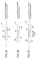
- Fig. 2A shows a state (mode) of the spherical aberration corrector plate 19 in a case where the disc's thickness of the optical disc 11 is thicker than the standard of 0.1 mm.
- Fig. 2B shows a state (mode) of the spherical aberration corrector plate 19 in a case where the disc's thickness of the optical disc 11 is equal to the standard of 0.1 mm.
- Fig. 2C shows a state (mode) of the spherical aberration corrector plate 19 in a case where the disc's thickness of the optical disc 11 is thinner than the standard of 0.1 mm.
- the spherical aberration corrector plate 19 comprises two wedge-shaped plates 33 and 35 having inclined planes 33a and 35a which are opposed to each other.
- the two wedge-shaped plates 33 and 35 have a constant refractive index.
- the two wedge-shaped plates 33 and 35 may be, for example, made of glass. However, they are not restricted to the glass, the two wedge-shaped plates 33 and 35 may be made of ones having the constant refractive index that are transparent to the laser ray.
- the two wedge-shaped plates 33 and 35 are enabled to relatively shift in at least a direction perpendicular to an optical axis of the optical pickup unit by a driving arrangement (not shown).
- Each of the two wedge-shaped plates 33 and 35 has both faces with antireflection coatings.
- the spherical aberration corrector plate 19 illustrated in Figs. 2A through 2C. It will be now assumed that the disc's thickness of the optical disc 11 is equal to the standard of 0.1 mm. In this event, the spherical aberration corrector plate 19 is not driven by the driving arrangement, as shown in Fig. 2B. Accordingly, the spherical aberration corrector plate 19 has an effective plate thickness of standard. Under the circumstances, inasmuch as the ray transmitted from the collimator lens 21 is the collimated ray, the collimated ray is supplied to the objective lens 27. It is therefore possible to make the ray from the objective lens 27 converge (irradiate) on the signal recording surface of the optical disc 11.
- the spherical aberration corrector plate 19 is shifted, by the driving arrangement, in a direction where the two wedge-shaped plates 33 and 35 approach to each other, as shown in an arrow of Fig. 2A. Accordingly, the spherical aberration corrector plate 19 has the effective plate thickness which is thicker than the standard (Fig. 2B). Under the circumstances, inasmuch as the ray transmitted from the collimator lens 21 is the diverged ray, the diverged ray is supplied to the objective lens 27. It is therefore possible to make the ray from the objective lens 27 converge (irradiate) on the signal recording surface of the optical disc 11.
- the spherical aberration corrector plate 19 is shifted, by the driving arrangement, in a direction where the two wedge-shaped plates 33 and 35 are apart from each other, as shown in an arrow of Fig. 2C. Accordingly, the spherical aberration corrector plate 19 has the effective plate thickness which is thinner than the standard (Fig. 2B). Under the circumstances, inasmuch as the ray transmitted from the collimator lens 21 is the converged ray, the converged ray is supplied to the objective lens 27. It is therefore possible to make the ray from the objective lens 27 converge (irradiate) on the signal recording surface of the optical disc 11.
- the spherical aberration is cancelled by changing parallelism (in a case of the infinite optical system) of a ray transmitted from the objective lens 27 to form spherical aberration reversing the spherical aberration occurring due to different disc's thicknesses of the optical disc 11.
- the method according to this invention belongs to the second method described in the prior art.
- the two wedge-shaped plates 33 and 35 are shifted with the inclined planes 33a and 35a in contact with each other by the driving arrangement. Accordingly, in the example being illustrated, the effective plate thickness of the spherical aberration corrector plate 19 is equal to a physical plate thickness thereof. However, it may be actually difficult to shift the two wedge-shaped plates 33 and 35 with the inclined planes 33a and 35a in contact with each other by the driving arrangement.
- Fig. 3A shows a state (mode) of the spherical aberration corrector plate 19A in a case where the disc's thickness of the optical disc 11 is thicker than the standard of 0.1 mm.
- Fig. 3B shows a state (mode) of the spherical aberration corrector plate 19A in a case where the disc's thickness of the optical disc 11 is equal to the standard of 0.1 mm.
- Fig. 3C shows a state (mode) of the spherical aberration corrector plate 19A in a case where the disc's thickness of the optical disc 11 is thinner than the standard of 0.1 mm.
- the spherical aberration corrector plate 19A comprises the two wedge-shaped plates 33 and 35.
- the two wedge-shaped plates 33 and 35 are relatively shifted in only the direction perpendicular to the optical axis of the optical pickup unit.
- the illustrated spherical aberration corrector plate 19A is similar to the spherical aberration corrector plate 19 illustrated in Figs. 2A through 2C except that a driving method (the driving arrangement) is different from each other.
- the two wedge-shaped plates 33 and 35 are put into a state where the inclined planes 33a and 35a are in contact with each other when the two wedge-shaped plates 33 and 35 extremely come close to each other (see Fig. 3A). Otherwise (see Figs. 3B and 3C), the two wedge-shaped plates 33 and 35 are put into a state where the inclined planes 33a and 35a are apart from each other.
- the spherical aberration corrector plate 19A having such structure it is possible to easily construct the driving arrangement as compared with that shown in Figs. 2A through 2C. Inasmuch as operation of the spherical aberration corrector plate 19A is similar to that of the spherical aberration corrector plate 19 illustrated in Figs. 2A through 2C, description thereof is omitted.
- the effective plate thickness thereof is changed in accordance with the disc's thickness of the optical disc 11 without the physical plate thickness thereof.
- the spherical aberration corrector plate 19A illustrated in Figs. 3A through 3C have plate thicknesses, which effectively act as the refractive index, equal to those of the spherical aberration corrector plate 19 illustrated in Figs. 2A through 2C, respectively.
- both of the two wedge-shaped plates 33 and 35 are shifted in the opposite direction to each other in the spherical aberration corrector plates 19 and 19A illustrated in Figs. 2A through 2C and Figs. 3A through 3C, one of the two wedge-shaped plates 33 and 35 may be fixed while the other may be shifted.
- Fig. 4 shows a relationship between the disc's thickness of the optical disc 11 and the effective plate thickness of the spherical aberration corrector plate 19 (19A) where the spherical aberration is kept to a minimum.
- Fig. 4 shows an example of the optimal effective plate thickness of the spherical aberration corrector plate 19 (19A) every the disc's thickness of the optical disc 11.
- the abscissa represents the disc's thickness [mm] of the optical disc 11 and the ordinate represents the effective plate thickness [mm] of the spherical aberration corrector plate 19 (19A).
- the description will be made as regards operation in a case of recording a signal (data) in the optical disc 11 using the optical pickup unit illustrated in Fig. 1.
- the spherical aberration corrector plate 19 (19A) is shifted, a part where the self-recording re-jitter of a cross-talk becomes minimum, and the effective plate thickness of the spherical aberration corrector plate 19 (19A) is made to the optimal thickness.
- the spherical aberration corrector plate 19 (19A) is preliminarily shifted to carry out test recording to the optical disc 11, and the optimal thickness is determined by reproducing test recorded data from the optical disc 11.
- Another method which will presently be described, may be adapted. That is, when the spherical aberration is increased, there is generally a tendency for a primary ring of a spot of the laser beam to increase in the signal recording surface of the optical disc 11. Accordingly, an increased amount of the primary ring is detected by a sensor (not shown), a circuit (not shown) for correcting the increased amount of the primary ring is provided, and the effective plate thickness of the spherical aberration corrector plate 19 (19A) is made to the optimal thickness.
- a method of driving the spherical aberration corrector plate 19 (19A) using a motor or the like may be adopted.
- Fig. 5 shows an example of a relationship between the disc's thickness of the optical disc 11 and wave aberration.
- the abscissa represents the disc's thickness [mm] of the optical disc 11 and the ordinate represents the wave aberration [m ⁇ (rms)].
- black diamonds represent simulation results in a case where there is no spherical aberration correction and black squares represent simulation results in a case where there is spherical aberration correction.
- one called aberration in an optical system indicates the wave aberration.
- the wave aberration has a component of a root mean square value of Seidel's five aberrations which will presently be described.
- the aberrations in a lens are classified into five items which are called the "Seidel's five aberrations" because L. von Seidel had put forward in the 1850s.
- the five items are (1) spherical, (2) astigmatism, (3) curvature of field, (4) coma, and (5) distortion.
- the Seidel's five aberrations if the spherical aberration becomes large, the wave aberration becomes large naturally.
- the object of this invention is to correct the aberration occurring caused by the disc's thickness and the aberration occurring caused by the disc's thickness is only the spherical aberration.
- the wave aberration is denoted in Fig. 5.
- assumption can be made in a case of differing from every optical disc and in another case of differing from every location (e.g. radial location) of one optical disc.
- a first correction method comprises the steps of preliminarily scanning the optical disc 11 in a radial direction by the optical pickup unit before recording/reproducing to detect the disc's thickness every radial location of the optical disc 11, and of memorizing its detected results in a memory (not shown) with the radial locations of the optical disc made as addresses of the memory.
- the first correction method further comprises the steps of accessing the memory with an actual radial location of the optical disc 11 made an address thereof to obtain a disc's thickness at that time, and of making the effective plate thickness of the spherical aberration corrector plate 19 (19A) change on the basis of the obtained disc's thickness.
- a second correction method comprises the steps of detecting a disc's thickness of the optical disc at a seeking location of the optical pickup unit at a real time, of making the effective plate thickness of the spherical aberration corrector plate 19 (19A) change at the real time on the basis of its detected result.
- the effective plate thickness of the spherical aberration corrector plate 19 (19A) change on the detected disc's thickness of the optical disc 11 it is possible, for example to adopt a method as follows.
- the method comprises the steps of preliminarily storing data indicative of the relationship between the disc's thickness of the optical disc and the effective plate thickness of the spherical aberration corrector plate having the minimum spherical aberration illustrated in Fig.
- ROM random access memory
- various methods can be adopted as a method (means) for detecting the disc's thickness of the optical disc 11.
- a detecting method (means) is disclosed in JP-2003-16660 A, JP-2003-22545 A, JP-2003-109239, and so on.
- the optical pickup consisting of the infinite optical system is described. Not being limited thereto, this invention is also applicable to an optical pickup having a finite optical system.
Landscapes
- Physics & Mathematics (AREA)
- Optics & Photonics (AREA)
- Chemical & Material Sciences (AREA)
- Crystallography & Structural Chemistry (AREA)
- Optical Head (AREA)
- Lenses (AREA)
- Investigating Or Analysing Materials By Optical Means (AREA)
Applications Claiming Priority (2)
| Application Number | Priority Date | Filing Date | Title |
|---|---|---|---|
| JP2003303387A JP2005071544A (ja) | 2003-08-27 | 2003-08-27 | 球面収差補正板、それを用いた光ピックアップ装置、および球面収差補正方法 |
| JP2003303387 | 2003-08-27 |
Publications (2)
| Publication Number | Publication Date |
|---|---|
| EP1511024A2 true EP1511024A2 (de) | 2005-03-02 |
| EP1511024A3 EP1511024A3 (de) | 2006-08-02 |
Family
ID=34101204
Family Applications (1)
| Application Number | Title | Priority Date | Filing Date |
|---|---|---|---|
| EP04253763A Withdrawn EP1511024A3 (de) | 2003-08-27 | 2004-06-23 | Korrekturplatte der sphärischen Aberration |
Country Status (4)
| Country | Link |
|---|---|
| US (1) | US20050047310A1 (de) |
| EP (1) | EP1511024A3 (de) |
| JP (1) | JP2005071544A (de) |
| CN (1) | CN1591624A (de) |
Families Citing this family (5)
| Publication number | Priority date | Publication date | Assignee | Title |
|---|---|---|---|---|
| JP2004152446A (ja) * | 2002-10-31 | 2004-05-27 | Samsung Electro Mech Co Ltd | 光ピックアップ装置及び液晶素子 |
| CN100466075C (zh) * | 2006-03-02 | 2009-03-04 | 精碟科技股份有限公司 | 光学读写头 |
| JP4825579B2 (ja) * | 2006-05-23 | 2011-11-30 | 株式会社日立製作所 | 光ディスク装置 |
| JP5161874B2 (ja) * | 2007-04-24 | 2013-03-13 | パナソニック株式会社 | 近接場光を用いて情報記録媒体に対するデータの記録および/または再生を行う装置および方法、および情報記録媒体 |
| JP2023142214A (ja) * | 2022-03-24 | 2023-10-05 | 株式会社Screenホールディングス | 光学装置、露光装置および露光方法 |
Family Cites Families (13)
| Publication number | Priority date | Publication date | Assignee | Title |
|---|---|---|---|---|
| US3960441A (en) * | 1972-10-06 | 1976-06-01 | Canon Kabushiki Kaisha | Anti-reflection coating having pseudo-inhomogeneous layers |
| JP2531626B2 (ja) * | 1986-04-10 | 1996-09-04 | オリンパス光学工業株式会社 | 光学的記録媒体用基盤の光学的特性測定装置 |
| US5255262A (en) * | 1991-06-04 | 1993-10-19 | International Business Machines Corporation | Multiple data surface optical data storage system with transmissive data surfaces |
| JPH05241095A (ja) * | 1992-03-02 | 1993-09-21 | Matsushita Electric Ind Co Ltd | 光ディスクの球面収差の補正方法とそれを用いた光ヘッド |
| JPH07105566A (ja) * | 1993-09-30 | 1995-04-21 | Nippon Columbia Co Ltd | 光ピックアップ装置 |
| JPH07121923A (ja) * | 1993-10-27 | 1995-05-12 | Olympus Optical Co Ltd | 光学式ピックアップヘッド装置 |
| JPH11110808A (ja) * | 1997-10-06 | 1999-04-23 | Fujitsu Ltd | 光学的情報記憶装置 |
| JP3545221B2 (ja) * | 1998-09-30 | 2004-07-21 | パイオニア株式会社 | 収差発生装置 |
| JP3640059B2 (ja) * | 1999-02-12 | 2005-04-20 | パイオニア株式会社 | 収差補正装置及びこれを用いた光学装置 |
| JP4136273B2 (ja) * | 2000-05-24 | 2008-08-20 | パイオニア株式会社 | 収差補正ユニット、光ピックアップ装置及び記録再生装置 |
| JP2002237076A (ja) * | 2001-02-06 | 2002-08-23 | Pioneer Electronic Corp | 収差補正装置 |
| JP3781273B2 (ja) * | 2001-02-07 | 2006-05-31 | パイオニア株式会社 | 収差補正素子及び収差補正ユニット |
| US7342869B2 (en) * | 2002-07-08 | 2008-03-11 | Sony Corporation | Optical-recording medium playback apparatus and optical-recording medium, including flying optical head features |
-
2003
- 2003-08-27 JP JP2003303387A patent/JP2005071544A/ja not_active Withdrawn
-
2004
- 2004-06-23 EP EP04253763A patent/EP1511024A3/de not_active Withdrawn
- 2004-06-29 US US10/881,831 patent/US20050047310A1/en not_active Abandoned
- 2004-07-09 CN CNA2004100697271A patent/CN1591624A/zh active Pending
Also Published As
| Publication number | Publication date |
|---|---|
| CN1591624A (zh) | 2005-03-09 |
| US20050047310A1 (en) | 2005-03-03 |
| JP2005071544A (ja) | 2005-03-17 |
| EP1511024A3 (de) | 2006-08-02 |
Similar Documents
| Publication | Publication Date | Title |
|---|---|---|
| KR100653289B1 (ko) | 광학 헤드 및 기록 재생 장치 | |
| TWI297491B (en) | Optical pickup using lens correcting wavefront error caused by tilt | |
| KR100388515B1 (ko) | 광학픽업장치 | |
| EP1117096B1 (de) | Optische Abtastvorrichtung | |
| US20080008078A1 (en) | Object lens for optical pickup, optical pickup and optical information processing device | |
| JP2002245656A (ja) | 光ピックアップ用2位置結像対物レンズ | |
| EP0807928B1 (de) | Vorrichtung zur optischen Abtastung und Objektivlinse dafür | |
| JP4144763B2 (ja) | 情報ピックアップ装置及び光ディスク装置 | |
| US7233562B2 (en) | Optical pickup device | |
| JPH0917011A (ja) | 二重焦点の光ピックアップ | |
| EP1511024A2 (de) | Korrekturplatte der sphärischen Aberration | |
| US6434104B2 (en) | Objective lens, optical pickup device and optical disk device | |
| JP2003077171A (ja) | 光ピックアップ装置及びこれに適用される記録媒体 | |
| JP2000339713A (ja) | 光ピックアップ装置 | |
| JP2003140036A (ja) | 光記録媒体用対物レンズおよびこれを用いた光ピックアップ装置 | |
| JPH11259891A (ja) | 光ヘッド装置 | |
| JP2000030290A (ja) | 光学ヘッド装置及び光ディスクの記録再生装置 | |
| JPH1164724A (ja) | 光ディスク用対物レンズ及びそれを用いた光ヘッド装置 | |
| KR100551777B1 (ko) | 색수차가 보정된 광 기록 및 재생장치 | |
| JPH11273123A (ja) | 光ヘッド装置 | |
| JPH09306014A (ja) | 光情報記録媒体の記録及び/又は再生用集光光学系、および対物レンズ | |
| JP4333807B2 (ja) | 情報ピックアップ装置及び光ディスク装置 | |
| JPH103686A (ja) | 情報ピックアップ装置及びその対物レンズ | |
| JPH10255306A (ja) | 光学ピックアップ装置 | |
| JP3986521B2 (ja) | 光ディスク装置 |
Legal Events
| Date | Code | Title | Description |
|---|---|---|---|
| PUAI | Public reference made under article 153(3) epc to a published international application that has entered the european phase |
Free format text: ORIGINAL CODE: 0009012 |
|
| AK | Designated contracting states |
Kind code of ref document: A2 Designated state(s): AT BE BG CH CY CZ DE DK EE ES FI FR GB GR HU IE IT LI LU MC NL PL PT RO SE SI SK TR |
|
| AX | Request for extension of the european patent |
Extension state: AL HR LT LV MK |
|
| PUAL | Search report despatched |
Free format text: ORIGINAL CODE: 0009013 |
|
| AK | Designated contracting states |
Kind code of ref document: A3 Designated state(s): AT BE BG CH CY CZ DE DK EE ES FI FR GB GR HU IE IT LI LU MC NL PL PT RO SE SI SK TR |
|
| AX | Request for extension of the european patent |
Extension state: AL HR LT LV MK |
|
| AKX | Designation fees paid | ||
| REG | Reference to a national code |
Ref country code: DE Ref legal event code: 8566 |
|
| STAA | Information on the status of an ep patent application or granted ep patent |
Free format text: STATUS: THE APPLICATION IS DEEMED TO BE WITHDRAWN |
|
| 18D | Application deemed to be withdrawn |
Effective date: 20060701 |