EP1511110A2 - Méthode de production d'énergie avec une pile à combustible à oxyde solide - Google Patents
Méthode de production d'énergie avec une pile à combustible à oxyde solide Download PDFInfo
- Publication number
- EP1511110A2 EP1511110A2 EP04015436A EP04015436A EP1511110A2 EP 1511110 A2 EP1511110 A2 EP 1511110A2 EP 04015436 A EP04015436 A EP 04015436A EP 04015436 A EP04015436 A EP 04015436A EP 1511110 A2 EP1511110 A2 EP 1511110A2
- Authority
- EP
- European Patent Office
- Prior art keywords
- sofc
- fuel cell
- afterburner
- liquefaction
- solid electrolyte
- Prior art date
- Legal status (The legal status is an assumption and is not a legal conclusion. Google has not performed a legal analysis and makes no representation as to the accuracy of the status listed.)
- Withdrawn
Links
Images


Classifications
-
- H—ELECTRICITY
- H01—ELECTRIC ELEMENTS
- H01M—PROCESSES OR MEANS, e.g. BATTERIES, FOR THE DIRECT CONVERSION OF CHEMICAL ENERGY INTO ELECTRICAL ENERGY
- H01M8/00—Fuel cells; Manufacture thereof
- H01M8/04—Auxiliary arrangements, e.g. for control of pressure or for circulation of fluids
- H01M8/04082—Arrangements for control of reactant parameters, e.g. pressure or concentration
- H01M8/04089—Arrangements for control of reactant parameters, e.g. pressure or concentration of gaseous reactants
- H01M8/04097—Arrangements for control of reactant parameters, e.g. pressure or concentration of gaseous reactants with recycling of the reactants
-
- H—ELECTRICITY
- H01—ELECTRIC ELEMENTS
- H01M—PROCESSES OR MEANS, e.g. BATTERIES, FOR THE DIRECT CONVERSION OF CHEMICAL ENERGY INTO ELECTRICAL ENERGY
- H01M8/00—Fuel cells; Manufacture thereof
- H01M8/06—Combination of fuel cells with means for production of reactants or for treatment of residues
- H01M8/0662—Treatment of gaseous reactants or gaseous residues, e.g. cleaning
- H01M8/0668—Removal of carbon monoxide or carbon dioxide
-
- H—ELECTRICITY
- H01—ELECTRIC ELEMENTS
- H01M—PROCESSES OR MEANS, e.g. BATTERIES, FOR THE DIRECT CONVERSION OF CHEMICAL ENERGY INTO ELECTRICAL ENERGY
- H01M8/00—Fuel cells; Manufacture thereof
- H01M8/10—Fuel cells with solid electrolytes
- H01M8/12—Fuel cells with solid electrolytes operating at high temperature, e.g. with stabilised ZrO2 electrolyte
- H01M2008/1293—Fuel cells with solid oxide electrolytes
-
- H—ELECTRICITY
- H01—ELECTRIC ELEMENTS
- H01M—PROCESSES OR MEANS, e.g. BATTERIES, FOR THE DIRECT CONVERSION OF CHEMICAL ENERGY INTO ELECTRICAL ENERGY
- H01M8/00—Fuel cells; Manufacture thereof
- H01M8/04—Auxiliary arrangements, e.g. for control of pressure or for circulation of fluids
- H01M8/04007—Auxiliary arrangements, e.g. for control of pressure or for circulation of fluids related to heat exchange
- H01M8/04014—Heat exchange using gaseous fluids; Heat exchange by combustion of reactants
- H01M8/04022—Heating by combustion
-
- H—ELECTRICITY
- H01—ELECTRIC ELEMENTS
- H01M—PROCESSES OR MEANS, e.g. BATTERIES, FOR THE DIRECT CONVERSION OF CHEMICAL ENERGY INTO ELECTRICAL ENERGY
- H01M8/00—Fuel cells; Manufacture thereof
- H01M8/24—Grouping of fuel cells, e.g. stacking of fuel cells
- H01M8/249—Grouping of fuel cells, e.g. stacking of fuel cells comprising two or more groupings of fuel cells, e.g. modular assemblies
-
- Y—GENERAL TAGGING OF NEW TECHNOLOGICAL DEVELOPMENTS; GENERAL TAGGING OF CROSS-SECTIONAL TECHNOLOGIES SPANNING OVER SEVERAL SECTIONS OF THE IPC; TECHNICAL SUBJECTS COVERED BY FORMER USPC CROSS-REFERENCE ART COLLECTIONS [XRACs] AND DIGESTS
- Y02—TECHNOLOGIES OR APPLICATIONS FOR MITIGATION OR ADAPTATION AGAINST CLIMATE CHANGE
- Y02E—REDUCTION OF GREENHOUSE GAS [GHG] EMISSIONS, RELATED TO ENERGY GENERATION, TRANSMISSION OR DISTRIBUTION
- Y02E60/00—Enabling technologies; Technologies with a potential or indirect contribution to GHG emissions mitigation
- Y02E60/30—Hydrogen technology
- Y02E60/50—Fuel cells
Definitions
- the invention relates to a method for the production of electrical energy with the help of a fuel cell, in particular a solid electrolyte fuel cell (SOFC). Furthermore, the invention relates to a device to carry out the aforementioned method.
- SOFC solid electrolyte fuel cell
- a fuel cell is an electrochemical cell the continuous chemical energy of a fuel and an oxidizing agent into electrical energy transforms.
- a fuel cell has a cathode, an electrolyte and an anode on.
- the cathode becomes an oxidant, z. Air and the anode becomes a fuel, z.
- the SOFC fuel cell is also called a high temperature fuel cell because its operating temperature is up to 1000 ° C.
- oxygen ions are formed in the presence of the oxidant.
- the oxygen ions pass through the electrolyte, which consists for example of yttrium and zirconium, and recombine on the anode side with the fuel (pure H 2 or hydrogen-containing fuel gas, such as CH 4 ) originating hydrogen to water. Recombination releases electrons, generating electrical energy.
- the reaction at the anode is:
- the fuel can be, inter alia, methane or methanol be provided.
- the mentioned fuels will be by reforming or oxidation u. a. in hydrogen or converted to hydrogen-rich gas.
- the reforming can be used both outside and inside (internal) Reforming take place.
- the following should be with the Term SOFC both a single solid electrolyte fuel cell as well as a fuel cell stack built therefrom be understood.
- the exhaust gas from the anode compartment generally comprises CO 2 and water in the form of water vapor.
- Concept studies show that SOFC technology can lead to a CO 2 -free power plant if there are some modifications in the process. This is desirable in particular in the context of a zero-emission process management.
- the electrolyte separates the oxygen from the air nitrogen in situ, so that the reaction products H 2 O and CO 2 are initially not mixed with N 2 .
- the electrochemical reaction is usually not complete. Typically, fuel efficiencies of about 85% are achieved.
- the N 2 problem can be solved by a basically simple modification of the process control.
- the SOFC is followed by an oxidation with pure oxygen.
- This oxidation can be carried out, for example, in an electrochemical post-combustion stage.
- different procedures are distinguished. In the first two variants listed below, the electrochemical oxidation with O 2 can in principle progress up to 100%. N 2 is then no longer introduced.
- the arrangement consists of a fuel cell bundle with electrodes and electrolyte.
- electrical energy is supplied from the outside to increase the O 2 flow.
- the negative voltage to be applied is in the range of a few hundred mV, thus comes close in magnitude to the typical SOFC cell voltage (about 800 mV). This causes a high energy intrinsic demand of the system. This leads disadvantageously to reduced net electrical efficiencies of the plant.
- the anode and the cathode exhaust gases are passed separately in a reactor on both sides of an oxygen-conducting membrane.
- the oxygen of the cathode gas selectively permeates the anode exhaust gas side, where it leads to the oxidation of H 2 and CO.
- the reactor with the oxygen-conducting membrane is electrically neutral to the outside (arrangement without electrodes), so it can not contribute to the production of electricity.
- Such an arrangement is known, for example, from US Pat. No. 6,432,565 B1.
- the active electrochemical afterburner it is known to connect another SOFC, which is operated at a lower current density than the main SOFC, since it operates in the range of low H 2 concentrations.
- the advantage here is that a very high electrical system efficiency can be achieved. Therefore, this process variant is extremely attractive.
- the object of the invention is to provide an improved method for generating electrical energy by means of a solid electrolyte fuel cell, in which a high efficiency is achieved and at the same time the CO 2 emissions are lowered. Furthermore, it is the object of the invention to provide a device suitable for carrying out the aforementioned method.
- the object of the invention can be achieved if the afterburning is carried out only after CO 2 compression.
- the amount of ballast gases, in particular N 2 which is very hindering for the CO 2 liquefaction on a regular basis, is then much lower.
- the process control according to the invention allows operation of the active electrochemical afterburner with lower fuel consumption, for. With 96% instead of 98%.
- the H 2 concentration at the end of the electrochemical process is then regularly at a value about twice as high compared to the previous concept (about 4 instead of 2 mol%).
- the residual gas produced after CO 2 compression which mainly consists of H 2 and CO, is recycled before the SOFC and can thus also be used to generate electricity. This then usually very high efficiencies can be achieved.
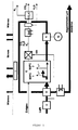
- FIG 1 the concept of a conventional power plant with a solid electrolyte fuel cell can be seen.
- SOFC is supplied with natural gas as the hydrogen-containing fuel gas and compressed air (K) as the oxidant.
- the air is preheated by a heat exchanger (W) through the cathode side exhaust stream.
- the non-fully reacted gases are fed to another SOFC as afterburner (SOFC 2).
- the cathode-side exhaust gas first drives a turbine (T) and serves to preheat the air.
- the anode-side exhaust gas is fed together with fresh air to a conventional afterburner (KN).
- KN conventional afterburner
- the now also containing N 2 hot exhaust gas is cooled.
- the water vapor is condensed out and the remaining exhaust gas then passes into a compressor / liquefaction unit (CO 2 -K), where the CO 2 is separated from the N 2 .
- CO 2 -K compressor / liquefaction unit
- FIG. 2 shows the concept of an embodiment according to the invention of the method for generating electrical energy by means of an SOFC.
- the flow chart differs from Figure 1 insofar as the afterburning of the anodic exhaust gas takes place only after the separation of the CO 2 (CO 2 -K) together with the cathodic exhaust gas. Without previously supplied N 2 , on the one hand the CO 2 separation from the anodic exhaust gas can be carried out much more effectively. On the other hand, an electrochemical afterburning can be tolerated with much less - and thus material less troublesome - implementation of the residual gases H 2 and CO.
- FIG. 3 shows a further embodiment of the invention.
- the CO 2 is first separated from the anodic exhaust gas (CO 2 -K).
- the remaining exhaust gas which now still has CO and H 2 , is now not post-combusted as in FIG. 2, but fed back to the main SOFC (SOFC 1) as fuel.
- SOFC 1 main SOFC
Landscapes
- Life Sciences & Earth Sciences (AREA)
- Sustainable Development (AREA)
- Engineering & Computer Science (AREA)
- Manufacturing & Machinery (AREA)
- Sustainable Energy (AREA)
- Chemical & Material Sciences (AREA)
- Chemical Kinetics & Catalysis (AREA)
- Electrochemistry (AREA)
- General Chemical & Material Sciences (AREA)
- Fuel Cell (AREA)
Applications Claiming Priority (2)
| Application Number | Priority Date | Filing Date | Title |
|---|---|---|---|
| DE10339079A DE10339079A1 (de) | 2003-08-26 | 2003-08-26 | Verfahren zur Erzeugung elektrischer Energie mit Hilfe einer Festelekrolyt-Brennstoffzelle |
| DE10339079 | 2003-08-26 |
Publications (2)
| Publication Number | Publication Date |
|---|---|
| EP1511110A2 true EP1511110A2 (fr) | 2005-03-02 |
| EP1511110A3 EP1511110A3 (fr) | 2007-04-04 |
Family
ID=34089189
Family Applications (1)
| Application Number | Title | Priority Date | Filing Date |
|---|---|---|---|
| EP04015436A Withdrawn EP1511110A3 (fr) | 2003-08-26 | 2004-07-01 | Méthode de production d'énergie avec une pile à combustible à oxyde solide |
Country Status (2)
| Country | Link |
|---|---|
| EP (1) | EP1511110A3 (fr) |
| DE (1) | DE10339079A1 (fr) |
Cited By (6)
| Publication number | Priority date | Publication date | Assignee | Title |
|---|---|---|---|---|
| WO2009059571A1 (fr) * | 2007-11-10 | 2009-05-14 | Horst-Eckart Vollmar | Système de cellule à combustible à haute température avec circuit partiel du gaz d'anode et évacuation de composants gazeux |
| WO2009085155A1 (fr) * | 2007-12-28 | 2009-07-09 | Saint-Gobain Ceramics & Plastics, Inc. | Système de pile à combustible |
| GB2486001A (en) * | 2010-12-01 | 2012-06-06 | Rolls Royce Fuel Cell Systems Ltd | A solid oxide fuel cell system and a method of operating a solid oxide fuel cell system |
| US8530101B2 (en) | 2007-08-08 | 2013-09-10 | Saint-Gobain Ceramics & Plastics, Inc. | Anode exhaust recycle system |
| US10256496B2 (en) | 2014-07-01 | 2019-04-09 | General Electric Company | Power generation systems and methods utilizing cascaded fuel cells |
| US10854899B2 (en) | 2016-11-04 | 2020-12-01 | Cummins Enterprise Llc | Power generation system using cascaded fuel cells and associated methods thereof |
Families Citing this family (1)
| Publication number | Priority date | Publication date | Assignee | Title |
|---|---|---|---|---|
| DE102008048376A1 (de) * | 2008-09-22 | 2010-04-01 | Köhne, Stephan, Dr. | Brennstoffzellensystem mit integrierter Gaserzeugung mit Anodenkreislauf und zugehöriges Verfahren zum Betrieb und zur Regelung und Steuerung des Betriebes |
Family Cites Families (3)
| Publication number | Priority date | Publication date | Assignee | Title |
|---|---|---|---|---|
| JPH05347161A (ja) * | 1992-06-12 | 1993-12-27 | Tokyo Electric Power Co Inc:The | 燃料電池発電システム |
| EP1025604B1 (fr) * | 1997-08-26 | 2001-11-07 | Shell Internationale Researchmaatschappij B.V. | Production d'energie electrique a partir de gaz naturel au moyen d'une pile a combustible oxyde solide |
| NL1014585C2 (nl) * | 2000-03-08 | 2001-09-21 | Kema Nv | Brandstofcel met een verbeterd rendement voor het opwekken van elektrische energie. |
-
2003
- 2003-08-26 DE DE10339079A patent/DE10339079A1/de not_active Withdrawn
-
2004
- 2004-07-01 EP EP04015436A patent/EP1511110A3/fr not_active Withdrawn
Cited By (13)
| Publication number | Priority date | Publication date | Assignee | Title |
|---|---|---|---|---|
| US8530101B2 (en) | 2007-08-08 | 2013-09-10 | Saint-Gobain Ceramics & Plastics, Inc. | Anode exhaust recycle system |
| WO2009059571A1 (fr) * | 2007-11-10 | 2009-05-14 | Horst-Eckart Vollmar | Système de cellule à combustible à haute température avec circuit partiel du gaz d'anode et évacuation de composants gazeux |
| US8343671B2 (en) | 2007-12-28 | 2013-01-01 | Saint-Gobain Ceramics & Plastics, Inc. | Fuel cell system having recycle fuel conduit in fluid communication with fuel cell assembly and carbon dioxide removal unit |
| WO2009085155A1 (fr) * | 2007-12-28 | 2009-07-09 | Saint-Gobain Ceramics & Plastics, Inc. | Système de pile à combustible |
| CN103238245A (zh) * | 2010-12-01 | 2013-08-07 | Lg燃料电池系统公司 | 固体氧化物燃料电池系统及其操作方法 |
| GB2486001B (en) * | 2010-12-01 | 2012-11-21 | Rolls Royce Fuel Cell Systems Ltd | A solid oxide fuel cell system and a method of operating a solid oxide fuel cell system |
| WO2012072400A1 (fr) | 2010-12-01 | 2012-06-07 | Rolls-Royce Fuel Cell Systems Limited | Système de pile à combustible à oxyde solide et procédé d'exploitation d'un système de pile à combustible à oxyde solide |
| GB2486001A (en) * | 2010-12-01 | 2012-06-06 | Rolls Royce Fuel Cell Systems Ltd | A solid oxide fuel cell system and a method of operating a solid oxide fuel cell system |
| CN103238245B (zh) * | 2010-12-01 | 2016-04-06 | Lg燃料电池系统公司 | 固体氧化物燃料电池系统及其操作方法 |
| AU2011335292B2 (en) * | 2010-12-01 | 2016-05-12 | Lg Fuel Cell Systems Inc. | A solid oxide fuel cell system and a method of operating a solid oxide fuel cell system |
| US9972855B2 (en) | 2010-12-01 | 2018-05-15 | Lg Fuel Cell Systems Inc. | Solid oxide fuel cell system and a method of operating a solid oxide fuel cell system |
| US10256496B2 (en) | 2014-07-01 | 2019-04-09 | General Electric Company | Power generation systems and methods utilizing cascaded fuel cells |
| US10854899B2 (en) | 2016-11-04 | 2020-12-01 | Cummins Enterprise Llc | Power generation system using cascaded fuel cells and associated methods thereof |
Also Published As
| Publication number | Publication date |
|---|---|
| DE10339079A1 (de) | 2005-03-24 |
| EP1511110A3 (fr) | 2007-04-04 |
Similar Documents
| Publication | Publication Date | Title |
|---|---|---|
| EP4097045B1 (fr) | Méthode et installation de production d'hydrogène | |
| EP0596366B1 (fr) | Procédé et dispositif pour évacuation de l'eau et des gaz inertes dans une batterie de piles à combustible | |
| DE19857398B4 (de) | Brennstoffzellensystem, insbesondere für elektromotorisch angetriebene Fahrzeuge | |
| DE69429332T2 (de) | Verfahren zur erzeugung elektrischer energie mittels feststoffpolymerzellen, gespeist mit kohlenwasserstoff | |
| DE19921816C1 (de) | Brennstoffzellen-System und Brennstoffzelle für derartiges System | |
| WO2000016423A2 (fr) | Cellule electrochimique fonctionnant avec un excedant de combustible | |
| DE19637207C2 (de) | Anlage und Verfahren zur Energieerzeugung | |
| EP4048827B1 (fr) | Méthode et dispositif de production d'un gaz de synthèse contenant du monoxyde de carbone et de l'hydrogène | |
| DE19941724A1 (de) | Brennstoffzelle betrieben mit Brennstoffüberschuß | |
| EP3714082A1 (fr) | Production électrochimique d'un gaz comprenant du co avec refroidissement intermédiaire du courant électrolytique | |
| EP1256142B1 (fr) | Pile a combustible alcaline a oxydation directe du methanol | |
| DE10339079A1 (de) | Verfahren zur Erzeugung elektrischer Energie mit Hilfe einer Festelekrolyt-Brennstoffzelle | |
| EP4127269B1 (fr) | Procédé et dispositif de synthèse d'ammoniac | |
| EP4283017A1 (fr) | Procédé et installation destinés à la mise en uvre d'un procédé de conversion de matière a l'aide d'une cellule à haute température | |
| WO2022058258A1 (fr) | Dispositif de pile à combustible à oxyde solide et véhicule à pile à combustible | |
| DE112021004409T5 (de) | Brennstoffzellen-stromerzeugungssystem und verfahren zur steuerung eines brennstoffzellen-stromerzeugungssystems | |
| EP1243046B1 (fr) | Optimisation des parametres de fonctionnement d'un systeme de pile a combustible directe a methanol | |
| DE102008034420A1 (de) | Verfahren und Vorrichtung zum Betreiben einer elektrochemischen Stromquelle | |
| DE102008038056A1 (de) | Verfahren und Vorrichtung zur Leistungssteigerung von Hochtemperatur-Brennstoffzellen | |
| EP1465276B1 (fr) | Pile à combustible basse température et procédé de fonctionnement associé | |
| EP4428266A1 (fr) | Procédé et installation pour obtenir un produit de synthèse à l'aide d'une électrolyse à haute température | |
| DE102021208146A1 (de) | Behandlung wasserstoffhaltiger und sauerstoffhaltiger Restgase von Brennstoffzellen | |
| DE102023205173A1 (de) | Kraftwerk und Verfahren zum Bereitstellen von elektrischem Strom | |
| DE68905186T2 (de) | Verfahren zur herstellung von ammoniak. | |
| DE102022120903A1 (de) | Strom- und Wärmeversorgung von Gebäuden und/oder industriellen Anlagen |
Legal Events
| Date | Code | Title | Description |
|---|---|---|---|
| PUAI | Public reference made under article 153(3) epc to a published international application that has entered the european phase |
Free format text: ORIGINAL CODE: 0009012 |
|
| AK | Designated contracting states |
Kind code of ref document: A2 Designated state(s): AT BE BG CH CY CZ DE DK EE ES FI FR GB GR HU IE IT LI LU MC NL PL PT RO SE SI SK TR |
|
| AX | Request for extension of the european patent |
Extension state: AL HR LT LV MK |
|
| PUAL | Search report despatched |
Free format text: ORIGINAL CODE: 0009013 |
|
| AK | Designated contracting states |
Kind code of ref document: A3 Designated state(s): AT BE BG CH CY CZ DE DK EE ES FI FR GB GR HU IE IT LI LU MC NL PL PT RO SE SI SK TR |
|
| AX | Request for extension of the european patent |
Extension state: AL HR LT LV MK |
|
| STAA | Information on the status of an ep patent application or granted ep patent |
Free format text: STATUS: THE APPLICATION HAS BEEN WITHDRAWN |
|
| 18W | Application withdrawn |
Effective date: 20070706 |