EP1511142A1 - Kabelkanal und Kabelrinnekupplung, Kabelrinne und Herstellungsverfahren dafür. - Google Patents
Kabelkanal und Kabelrinnekupplung, Kabelrinne und Herstellungsverfahren dafür. Download PDFInfo
- Publication number
- EP1511142A1 EP1511142A1 EP04356147A EP04356147A EP1511142A1 EP 1511142 A1 EP1511142 A1 EP 1511142A1 EP 04356147 A EP04356147 A EP 04356147A EP 04356147 A EP04356147 A EP 04356147A EP 1511142 A1 EP1511142 A1 EP 1511142A1
- Authority
- EP
- European Patent Office
- Prior art keywords
- chute
- longitudinal
- wire
- transverse
- lattice
- Prior art date
- Legal status (The legal status is an assumption and is not a legal conclusion. Google has not performed a legal analysis and makes no representation as to the accuracy of the status listed.)
- Withdrawn
Links
- 238000004519 manufacturing process Methods 0.000 title claims abstract description 6
- 238000000034 method Methods 0.000 title abstract 2
- 230000008878 coupling Effects 0.000 title description 2
- 238000010168 coupling process Methods 0.000 title description 2
- 238000005859 coupling reaction Methods 0.000 title description 2
- 239000002184 metal Substances 0.000 claims description 10
- 230000000630 rising effect Effects 0.000 claims description 6
- 238000005304 joining Methods 0.000 claims description 2
- 238000009434 installation Methods 0.000 description 6
- 238000003860 storage Methods 0.000 description 4
- 230000005489 elastic deformation Effects 0.000 description 2
- 238000003466 welding Methods 0.000 description 2
- FGRBYDKOBBBPOI-UHFFFAOYSA-N 10,10-dioxo-2-[4-(N-phenylanilino)phenyl]thioxanthen-9-one Chemical compound O=C1c2ccccc2S(=O)(=O)c2ccc(cc12)-c1ccc(cc1)N(c1ccccc1)c1ccccc1 FGRBYDKOBBBPOI-UHFFFAOYSA-N 0.000 description 1
- 241000251468 Actinopterygii Species 0.000 description 1
- 241001080024 Telles Species 0.000 description 1
- 230000005540 biological transmission Effects 0.000 description 1
- 239000000203 mixture Substances 0.000 description 1
- 230000037361 pathway Effects 0.000 description 1
- 239000011435 rock Substances 0.000 description 1
- 238000007493 shaping process Methods 0.000 description 1
- 239000007787 solid Substances 0.000 description 1
- 125000006850 spacer group Chemical group 0.000 description 1
Images





Classifications
-
- H—ELECTRICITY
- H02—GENERATION; CONVERSION OR DISTRIBUTION OF ELECTRIC POWER
- H02G—INSTALLATION OF ELECTRIC CABLES OR LINES, OR OF COMBINED OPTICAL AND ELECTRIC CABLES OR LINES
- H02G3/00—Installations of electric cables or lines or protective tubing therefor in or on buildings, equivalent structures or vehicles
- H02G3/02—Details
- H02G3/06—Joints for connecting lengths of protective tubing or channels, to each other or to casings, e.g. to distribution boxes; Ensuring electrical continuity in the joint
- H02G3/0608—Joints for connecting non cylindrical conduits, e.g. channels
Definitions
- the present invention relates to the field of cable trays or the like consisting of a succession trunking of the trellis type of welded wire together. More precisely, it concerns such chute, an assembly splint of two chutes of this type put end to end and a path for cables. She also relates to a method of manufacturing a chute wire mesh welded together.
- This splice starts with the hooking simultaneous of a curved rim to a longitudinal thread of a bottom of one of the chutes and the other recurved ledge to a longitudinal thread from one bottom of the other chute. Then, while keeping the edges hung, we rock the splice up until the clipping legs clip on longitudinal threads of sides that have the chutes.
- This splint can not be installed only after the two chutes, so that it does not can not be pre-mounted on one of these chutes.
- a cable tray is generally supported either by brackets, either by consoles that can be fixed directly on the wall or mounted on vertical bars, this which makes it possible to walk several paths one above others.
- the purpose of the invention is to simplify the storage and transport of these parts.
- the invention relates to a chute for pathways for cables or the like, this chute comprising longitudinal and transverse threads metal welded into a trellis that defines a bottom of the chute, as well as first and second sides rising to from this bottom, characterized in that it is provided at least one lattice assembly side lug of metal wires welded together, this bracket assembly protruding from one end of the chute to be able to secured to another chute.
- the subject of the invention is a splint side intended to equip a trough as defined above, characterized in that it comprises a trellis of metal wires welded together, at least two first. lower and upper fingers of the splice a first chute, as well as at least two second lower and upper fingers of the splice a second chute, the first and second fingers lower fasteners being set apart one of the other to a first longitudinal thread among the sons of the lattice of the splint, the first and second fingers upper fastening being set apart one of the other to a second longitudinal thread among the sons of the lattice of the splint, while some transverse wires among the threads of the lattice of the splint connect the first longitudinal wire to the second longitudinal wire and comprise at least one curved section between these first and second longitudinal son.
- the subject of the invention is also a path for cables or the like, including a first chute with longitudinal and transverse threads metal welded into a trellis that defines a bottom of this first chute, as well as two sides rising to from this bottom, a first and a second thread of the longitudinal threads of the first chute respectively forming part of the bottom of this first chute and one side of said first chute, characterized in that it comprises a second chute as defined above, the lower finger and the finger are respectively attached to the first and the second longitudinal wire of the first chute.
- the first longitudinal wire of the assembly tab and the first longitudinal wire of the first chute are on the same side of a first wire transverse among the transverse threads of the first chute, lower hooking finger and first wire cross section of the first chute being on the same side of the first longitudinal wire of the first chute, the second longitudinal thread of the assembly tab and the second longitudinal thread of the first chute being on the same side of the first transverse wire of the first chute, the upper hooking finger and the first wire cross section of the first chute being on the same side of the second longitudinal thread of the first chute.
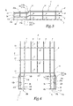
- This chute 1 which is shown alone in FIGS. 3 and 4, is symmetrical with respect to a longitudinal and vertical plane P. It consists of a lattice resulting from the welding of transverse metal wires 2 to longitudinal metal wires, which extend from one end of chute 1 to the other.
- This son welded mesh assembly defines a bottom of the chute 1, both sides of the chute 1, and two mounting lugs 3a and 3b which extend from one end of the duct 1 so as to face one from the other.
- Each side of chute 1 rises from the bottom and has three longitudinal threads, the lowest of which is referenced 4 and extends away from the other two. These last, referenced 6 and 7, are contiguous.
- Reference 7 designates the longitudinal wire of the bottom which is closest to one of the sides of chute 1, as well that the longitudinal wire of the bottom that is closest to the other side of chute 1. Other wires longitudinal of the bottom of the chute 1 are referenced 8.
- Each transverse wire 2 has the overall shape of a U and comprises two sections 9 forming amount, as well as a section 10 which forms crosses and connects these sections 9 one to the other.
- This section 10 is part of the bottom of the chute 1, while the sections 9 belong respectively to alongside this chute 1.
- Each section 9 ends upwards by an open loop 11 that surrounds close two longitudinal son 5 and 6 contiguous.
- the lateral mounting lugs 3a and 3b are symmetrical with respect to plane P, so that only the one referenced 3 is described in detail in the following.
- the references used hereafter to designate portions of the side lug assembly 3 b are constructed by substituting a b le through which ends the identifying reference like parts on the leg 3a.
- the lateral assembly lug 3a includes end portions 4a, 5a, 6a and 7a of the longitudinal son 4, 5, 6 and 7.
- the end portion 7a has a bent portion 14a and a straight section 15 a extending parallel to the longitudinal direction of the chute 1, from one of the son 13 a to the other wire 13 has .
- the bent portion 14a connects the straight section 15 has the rest of the longitudinal wire 7.
- 7 longitudinal wire extends along a rectilinear axis A 1, the straight section 15 is offset parallel to the bottom of the chute 1, that is to say horizontally, an amount equal to the diameter of the longitudinal son 7.
- the end portion 6a includes a bent portion 16a and a straight section 17a, which extends parallel to the longitudinal direction of the channel, from one of the son 13 a to the other wire 13 a.
- the bent portion 16a connects the straight section 17 has the rest of the longitudinal wire 6.
- 6 longitudinal wire extends along a rectilinear axis A 2, the straight portion 17a is offset parallel to the sides of the chute 1, that is to say vertically.
- Each son has 13 ends in a lower finger hook 18a, which extends from the end portion 17a toward the lateral tab assembly 3b.
- each of the son comprises a section 13 has a curve 22 between the end portions 6a and 7a. The end portion 7a and the hooking fingers 18 of a part of a lower edge 19 a of the assembly lug 3a.
- the wire 12 a is welded to the end portion 4a and the end portion 6a, beyond which it forms an upper finger hook 20 directed upwards.
- step which follows and illustrated in Figure 7 grip the lower fingers 18a to this thread 7 'by passing them from one side thereof to the other, using the screwdriver 21 that it is tilted for this purpose, so as to use it as a lever bearing on the longitudinal wire 7 '.
- the curved sections 22a are configured so as to facilitate elastic deformation of the son 13a during hooking fingers 18 a.
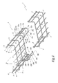
- Figure 5 illustrates how the lateral connecting tab 3a is attached to the chute 1 ', when the latter and the drop chute 1 are assembled.
- the contact between the snap finger 20 and a longitudinal wire 5 ', on the one hand, and contact between the end portion 6a and two transverse son 2', on the other hand, means that the lateral tab assembly 3a and the side of the chute 1 'on which it is mounted can not be separated from one another.
- Contacts between the end portion 7 a and both transverse son 2 'mentioned above, on the one hand, and the contact between a longitudinal thread 7' and the hooking fingers 18 has, on the other hand, make the bottom edge 19 a and the bottom of the chute 1 'can not be separated from one another.
- the transmission of force from one of the ducts 1 and 1 'to each other is further enhanced by the presence of a contact between a longitudinal thread 4' and the wire 12 a, as well as contacts between the longitudinal wire 5 'and loops 11 through which the son 13 has ends opposite the hooking fingers 18 a.
- One and the other side leg assembly 103 a and 103 b of a chute 101 are disposed respectively to one and the other end of the chute 101. Both can extend or not the same side of the chute 1.
- the insert wire 12 a is removed as many fingers hooking 120a are defined by the son 113. It is the same at the level of the bracket 103 b .
- chutes 101 No part other than chutes 1 and 1 'is necessary for the assembly of these chutes 1 and 1 '. it also applies to chutes 101 and results in a decrease in the number of parts needed to install a path for cables. It follows from a simplification of storage and transport of these parts in accordance with the purpose of the invention. This is of practical interest and leads in addition to a reduction in the overall cost of the path for cables.
- the lateral mounting lugs 3 a, 3 b, 103 a and 103b have the advantage of being very robust. They also have the advantage of being easy to manufacture, which results in a low cost.
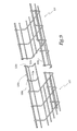
- FIG 10 is partially shown a cable path according to a third embodiment of the invention.
- This cable path has two identical trunking 201 and 201 'end-to-end, of which one is shown alone in Figure 11.
- Each of the two ends of a chute 201 is provided with one of the two lateral mounting tabs, which are identical and only one, referenced 203 a , is visible in Figure 11 and described below.
- This tab 203 is attached to the chute 201. More specifically, it is an end portion of a splice assembly 223 mounted on the chute 201.
- This splint 223, which is shown alone at FIG. 12, consists of a lattice resulting from the welding of transverse wires 224, 225 and 226 to a lower longitudinal wire 227 and a wire upper longitudinal metal 228.
- the transverse yarn 224 is a middle yarn extending substantially equidistant from both ends of 223.
- Each of the transverse wires 225 in number of two, is placed at one end of the splint 223, he defines an edge.
- each wire 226 protrudes to the top of the upper longitudinal wire 228 and forms a finger top hanging 220.
- Each of the wires 225 and 226 has a portion end protruding from the lower longitudinal wire 227 and forms a lower hooking finger 218.
- Each of the transverse wires 224, 225 and 226 comprises a curved section 222 between the longitudinal wires 227 and 228, which facilitates its elastic deformation during the attachment, described hereinafter, of the fingers 218 and 220.
- the installation of the splice 223 on the chute 201 comprises two steps, the first of which is to hook two lower fingers 218, located on the same side of the middle wire 224, to a longitudinal wire 207 of the bottom of the chute 201.
- the second step of the installation of the splint 223 on the trough 201 is illustrated in FIG. 13 and consists in hooking one of the upper fingers 220 to the wires 205 and 206 on one side of the trough 201.
- a lever is used as a screwdriver 21, which is tilted over the wire 205 above, in the direction indicated by the arrow F 2 , to press the wire 228 of the splint 223.
- the tab 203 has an upper finger equivalent hooking finger 20 a or 120 a and consists of a finger 220. It also has two lower fingers equivalent snap fingers 18 has and constituted by two fingers 218.
- the two troughs 201 are as illustrated in FIG. 10 and are held together by the two lateral splints 223.
- Each of these two splints 223 is hooked onto the two troughs 201 in such a way that its median wire 224 is located between these chutes 201.
- the middle son 224 thus fulfill the function of spacers maintaining a gap e between the chutes 201.
- the assembly of two chutes 201 using two 223 splints can take place only after one at less of these 223 splints was installed on one of 201. It follows that the fishplates 223 can be pre-assembled on the trunking 201. Where this is the case, the management of the transport and storage of fish 223 is superfluous since it results from the management of the transport and storage trunks 201 that these fishplates equip.
- the ribs 223 thus make it possible to reach the purpose mentioned in the introduction to this text.
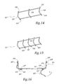
- FIG 14 is shown a splint 323 according to a fourth embodiment of the invention.
- This splint 323 is distinguished from splint 223 in that has not five transverse wires 224, 225 and 226, but only three transverse wires 324 and 325, of which each in the same shape as a wire 226.
- the wire 324 is a wire median as the wire 224.
- Each of the two wires 325 is placed at one end of the splint 323 and defines a finger lower hanging 318, similar to one of the fingers 218, and a top hooking finger 320, similar to one of the fingers 220.
- the splint 323 is identical to the splint 223.
- FIG 15 is shown a splint 423 according to a fifth embodiment of the invention.
- This splint 423 is identical to splint 223, except that two of his lower hooking fingers are bent and form hooks 429, and in that its middle thread, referenced 424, defines a lower finger 430 of longitudinal positioning of the splint 423 relative two chutes intended to be assembled by this splint.
- the two hooks 429 are arranged on both sides other of the middle thread 424 and partially surround the thread longitudinal lower, referenced 427, of the splint 423.
- FIG 16 In Figure 16 are shown a first chute 201 and two fishplates 423, one maintains assembled one side of the first chute 201 and one side of a second chute 201 masked by the first chute.
- One and the other hook 429 of the other splint 423 which is being installed, are respectively hooked to a longitudinal wire 207 of the bottom of the first chute 201 and to a longitudinal wire 207 of the bottom of the second chute 201.
- this other splint 423 can be tilted upward (arrow F 3 ), to complete its installation by hooking its upper gripping fingers, referenced 420, son 205 and 206 of the first and second chute 201.
- the lugs 3 a, 3 b, 103 a, and 103 b, and the sides 223, 323 and 423 have an appearance that blends with one of the ducts 1, 1 ' , 101, 101 'and 201, since all these elements are in wire mesh welded together.
Landscapes
- Engineering & Computer Science (AREA)
- Architecture (AREA)
- Civil Engineering (AREA)
- Structural Engineering (AREA)
- Wire Processing (AREA)
Applications Claiming Priority (2)
| Application Number | Priority Date | Filing Date | Title |
|---|---|---|---|
| FR0310139 | 2003-08-25 | ||
| FR0310139A FR2859318B1 (fr) | 2003-08-25 | 2003-08-25 | Goulotte et eclisse pour chemin pour cables, chemin pour cables et procede de fabrication d'une telle goulotte |
Publications (1)
| Publication Number | Publication Date |
|---|---|
| EP1511142A1 true EP1511142A1 (de) | 2005-03-02 |
Family
ID=34089852
Family Applications (1)
| Application Number | Title | Priority Date | Filing Date |
|---|---|---|---|
| EP04356147A Withdrawn EP1511142A1 (de) | 2003-08-25 | 2004-08-24 | Kabelkanal und Kabelrinnekupplung, Kabelrinne und Herstellungsverfahren dafür. |
Country Status (2)
| Country | Link |
|---|---|
| EP (1) | EP1511142A1 (de) |
| FR (1) | FR2859318B1 (de) |
Cited By (7)
| Publication number | Priority date | Publication date | Assignee | Title |
|---|---|---|---|---|
| WO2009121976A1 (es) * | 2008-03-31 | 2009-10-08 | Interflex, S. A. | Tramo acoplable para bandejas portacables |
| ES2363320A1 (es) * | 2011-05-20 | 2011-07-29 | Pemsa Pequeño Material Eléctrico, S.A. | Dispositivo de empalme de tramos de bandeja portacables del tipo escalera, tramo de bandeja y procedimiento de sustitución de dichos tramos. |
| FR2971100A1 (fr) * | 2011-01-31 | 2012-08-03 | Gewiss France Sas | Goulotte pour chemin de cables et chemin de cables comprenant une telle goulotte |
| EP2688167A1 (de) * | 2012-07-19 | 2014-01-22 | Gewiss France SA | Rinne für Kabelkanal, und Kabelkanal, der eine solche Rinne umfasst |
| DE102013224380A1 (de) | 2013-06-20 | 2014-12-24 | Niedax France | Transversales einrastendes Kabelkanalteilstück, Kabelkanal mit solchen Teilstücken und Herstellungsverfahren |
| FR3080227A1 (fr) * | 2018-04-11 | 2019-10-18 | Gewiss France Sas | Systeme de chemin de cables et methode de fixation d'une eclisse sur un troncon de chemin de cables en treillis |
| EP3872942A1 (de) | 2020-02-25 | 2021-09-01 | Niedax GmbH & Co. KG | Kabelkanal mit polygonalem querschnitt, und zusammenbauverfahren solcher kabelkanäle |
Citations (3)
| Publication number | Priority date | Publication date | Assignee | Title |
|---|---|---|---|---|
| FR2687207A1 (fr) * | 1992-02-11 | 1993-08-13 | Mavil | Eclisses pour treillis en fils soudes. |
| US6193434B1 (en) * | 1996-07-26 | 2001-02-27 | Metal Deploye S.A. | Connecting splice for cable trough sections, and resulting cable trough sections |
| US6239364B1 (en) * | 1998-07-11 | 2001-05-29 | Otto Bettermann Gmbh & Co. Kg | Wire-mesh cable trough |
-
2003
- 2003-08-25 FR FR0310139A patent/FR2859318B1/fr not_active Expired - Fee Related
-
2004
- 2004-08-24 EP EP04356147A patent/EP1511142A1/de not_active Withdrawn
Patent Citations (3)
| Publication number | Priority date | Publication date | Assignee | Title |
|---|---|---|---|---|
| FR2687207A1 (fr) * | 1992-02-11 | 1993-08-13 | Mavil | Eclisses pour treillis en fils soudes. |
| US6193434B1 (en) * | 1996-07-26 | 2001-02-27 | Metal Deploye S.A. | Connecting splice for cable trough sections, and resulting cable trough sections |
| US6239364B1 (en) * | 1998-07-11 | 2001-05-29 | Otto Bettermann Gmbh & Co. Kg | Wire-mesh cable trough |
Cited By (9)
| Publication number | Priority date | Publication date | Assignee | Title |
|---|---|---|---|---|
| WO2009121976A1 (es) * | 2008-03-31 | 2009-10-08 | Interflex, S. A. | Tramo acoplable para bandejas portacables |
| FR2971100A1 (fr) * | 2011-01-31 | 2012-08-03 | Gewiss France Sas | Goulotte pour chemin de cables et chemin de cables comprenant une telle goulotte |
| ES2363320A1 (es) * | 2011-05-20 | 2011-07-29 | Pemsa Pequeño Material Eléctrico, S.A. | Dispositivo de empalme de tramos de bandeja portacables del tipo escalera, tramo de bandeja y procedimiento de sustitución de dichos tramos. |
| EP2688167A1 (de) * | 2012-07-19 | 2014-01-22 | Gewiss France SA | Rinne für Kabelkanal, und Kabelkanal, der eine solche Rinne umfasst |
| DE102013224380A1 (de) | 2013-06-20 | 2014-12-24 | Niedax France | Transversales einrastendes Kabelkanalteilstück, Kabelkanal mit solchen Teilstücken und Herstellungsverfahren |
| EP2816687A1 (de) | 2013-06-20 | 2014-12-24 | Niedax France | Kabelpritschenabschnitt mit quer verlaufenden Einrastvorrichtungen, Kabelpritsche, die solche Abschnitte umfasst, und Herstellungsverfahren |
| EP2816687B1 (de) | 2013-06-20 | 2015-08-19 | Niedax France | Kabelpritschenabschnitt mit quer verlaufenden Einrastvorrichtungen, Kabelpritsche, die solche Abschnitte umfasst, und Herstellungsverfahren |
| FR3080227A1 (fr) * | 2018-04-11 | 2019-10-18 | Gewiss France Sas | Systeme de chemin de cables et methode de fixation d'une eclisse sur un troncon de chemin de cables en treillis |
| EP3872942A1 (de) | 2020-02-25 | 2021-09-01 | Niedax GmbH & Co. KG | Kabelkanal mit polygonalem querschnitt, und zusammenbauverfahren solcher kabelkanäle |
Also Published As
| Publication number | Publication date |
|---|---|
| FR2859318B1 (fr) | 2005-10-07 |
| FR2859318A1 (fr) | 2005-03-04 |
Similar Documents
| Publication | Publication Date | Title |
|---|---|---|
| EP0556137B1 (de) | Verbinder für geschweisste Gitter | |
| EP0479227B1 (de) | Vorrichtung zur Montage und Befestigung von einzelnen Modulen auf einem Halterahmen | |
| EP2838170B1 (de) | Kabelkanal, der eine Rinne aus geschweißtem Drahtgeflecht und ein Befestigungselement umfasst, und Befestigungselement für eine solche Rinne | |
| EP1000284A1 (de) | Kabelrinne aus metalldrahtgitter mit mindestens einer befestigungsvorrichtung und entsprechender befestigungsvorrichtung | |
| EP2221518B1 (de) | Verbindungselement eines Abschnitts eines Kabelkanals aus Drahtgitter auf einer armförmigen Konsole | |
| FR2751723A1 (fr) | Eclisse d'assemblage pour troncons de chemins de cables et troncons de chemins de cables obtenus | |
| EP1192693A1 (de) | Befestigungsvorrichtung für kabelrinne aus metalldrahtgitter und damit ausgerüstete kabelrinne | |
| EP1511142A1 (de) | Kabelkanal und Kabelrinnekupplung, Kabelrinne und Herstellungsverfahren dafür. | |
| EP0418167B1 (de) | Schnellverbinder für verlotete Kabelrinne aus Metalldrahtgitter | |
| EP2830173B1 (de) | Kabelkanalanordnung | |
| EP0986849B1 (de) | Kabelkanal und zubehör dafür | |
| EP0813012B1 (de) | Elektrischer Kabelträger und Kabelrinne mit solchen Trägern | |
| FR2711208A1 (fr) | Eclisse pour assemblage de tronçons de chemins de câbles. | |
| EP1542329B1 (de) | Montagekonsole für Kabelkanäle | |
| EP1505702B1 (de) | Verbindungselement für zwei Kabelrinnen aus Drahtgitter, Kabelrinne aus Drahtgitter und Kabelkanal dieses enthaltend | |
| EP0725467B1 (de) | Befestigungsvorrichtung zur Verbindung von Stahlblechkabelrinnen | |
| EP2768098B1 (de) | Verbinder für Kabelrinnenabschnitte aus Drahtgitter | |
| FR2857792A1 (fr) | Eclisse et support de conduits en treillis comportant au moins deux troncons relies par une telle eclisse | |
| FR2853463A1 (fr) | Console de support de chemin de cables | |
| FR2937399A1 (fr) | Piece d'assemblage de troncons de chemin de cables en treillis de fils coulissant et chemin de cables equipe d'une telle piece. | |
| EP0999627B1 (de) | Sockel für Kabelkanal mit vorgeformten Bohrungen und Verfahren ihrer Herstellung | |
| FR2937400A1 (fr) | Piece d'assemblage de troncons de chemin de cables en treillis de fils pouvant prendre deux positions et chemin de cables equipe d'une telle piece. | |
| EP4118721B1 (de) | Kabelführungslänge mit einem fischplattierten ende | |
| FR2757696A1 (fr) | Console pour conduits porteurs | |
| EP1241757A1 (de) | Kabelkanalelement |
Legal Events
| Date | Code | Title | Description |
|---|---|---|---|
| PUAI | Public reference made under article 153(3) epc to a published international application that has entered the european phase |
Free format text: ORIGINAL CODE: 0009012 |
|
| AK | Designated contracting states |
Kind code of ref document: A1 Designated state(s): AT BE BG CH CY CZ DE DK EE ES FI FR GB GR HU IE IT LI LU MC NL PL PT RO SE SI SK TR |
|
| AX | Request for extension of the european patent |
Extension state: AL HR LT LV MK |
|
| 17P | Request for examination filed |
Effective date: 20050509 |
|
| AKX | Designation fees paid |
Designated state(s): DE ES FR GB IT |
|
| 17Q | First examination report despatched |
Effective date: 20091223 |
|
| GRAP | Despatch of communication of intention to grant a patent |
Free format text: ORIGINAL CODE: EPIDOSNIGR1 |
|
| STAA | Information on the status of an ep patent application or granted ep patent |
Free format text: STATUS: THE APPLICATION IS DEEMED TO BE WITHDRAWN |
|
| 18D | Application deemed to be withdrawn |
Effective date: 20100824 |