EP1511432B1 - Instrument chirurgical presentant un blocage de collier et un systeme d'indexation - Google Patents
Instrument chirurgical presentant un blocage de collier et un systeme d'indexation Download PDFInfo
- Publication number
- EP1511432B1 EP1511432B1 EP03739050.7A EP03739050A EP1511432B1 EP 1511432 B1 EP1511432 B1 EP 1511432B1 EP 03739050 A EP03739050 A EP 03739050A EP 1511432 B1 EP1511432 B1 EP 1511432B1
- Authority
- EP
- European Patent Office
- Prior art keywords
- motor assembly
- housing
- collet
- engaging means
- surgical instrument
- Prior art date
- Legal status (The legal status is an assumption and is not a legal conclusion. Google has not performed a legal analysis and makes no representation as to the accuracy of the status listed.)
- Expired - Lifetime
Links
Images



Classifications
-
- A—HUMAN NECESSITIES
- A61—MEDICAL OR VETERINARY SCIENCE; HYGIENE
- A61B—DIAGNOSIS; SURGERY; IDENTIFICATION
- A61B17/00—Surgical instruments, devices or methods
- A61B17/16—Instruments for performing osteoclasis; Drills or chisels for bones; Trepans
- A61B17/1613—Component parts
- A61B17/162—Chucks or tool parts which are to be held in a chuck
-
- A—HUMAN NECESSITIES
- A61—MEDICAL OR VETERINARY SCIENCE; HYGIENE
- A61B—DIAGNOSIS; SURGERY; IDENTIFICATION
- A61B17/00—Surgical instruments, devices or methods
- A61B17/16—Instruments for performing osteoclasis; Drills or chisels for bones; Trepans
- A61B17/1613—Component parts
- A61B17/1633—Sleeves, i.e. non-rotating parts surrounding the bit shaft, e.g. the sleeve forming a single unit with the bit shaft
Definitions
- the present disclosure generally relates to surgical instruments and their use. More particularly, the present disclosure relates to a collet locking and indexing system for surgical instruments.
- Surgical instruments in general, should satisfy several requirements in order to fulfill their various roles during surgery.
- One requirement is that certain components of a multi-part instrument, such as an instrument used for dissecting bone or tissue, should be aligned properly when the instrument is assembled.
- alignment-sensitive components forming the instrument should be in certain positions relative to the other components when the instrument is originally assembled. Thereafter, each time the instrument is reassembled after being disassembled, each of the alignment-sensitive components should be returned to the same relative position.
- consistent alignment ensures that the instrument is correctly positioned to receive a surgeon's hand in an optimal manner.
- Such optimal alignment may take into account such factors as the location of any controls and the angle of a tool associated with the instrument, such as a cutting tool. If the alignment of the various components is not correct, a surgeon may be unable to access the controls when the cutting tool is properly positioned.
- marks are placed on the exterior of the instrument in the following manner.
- the instrument which often includes a locking device such as a collet, a motor and motor assembly, and an attachment, is fully assembled.
- the assembly process includes attaching the collet to the motor assembly, sliding the attachment over the collet, and securing the attachment to the collet. Marks may then be made on the exterior of the motor assembly and the attachment to indicate their relative positions ("locked” or “unlocked”) when the instrument is fully assembled.
- the attachment is loosened (moved to the "unlocked” position), the collet is opened and the tool is inserted into the collet.
- the collet is then closed to securely retain the tool and the attachment is tightened until the mark on the attachment is aligned with the corresponding mark on the motor assembly (the "locked" position). Accordingly, the alignment marks prevent the attachment from being over-tightened, which could damage the instrument, and from not being tightened enough, which could have disastrous consequences during surgery. As the alignment marks depend on the relative positions of the attachment, motor assembly, and collet, these components play an important role in the alignment process.
- a tool holder comprising a collet housing suitable for rotationally locking a surgical tool (16) to a motor, the collet housing including a first engaging means and a third engaging means , a motor assembly comprising the motor and operable to receive the collet housing in a cavity of the motor assembly, the cavity including a second engaging means operable to engage the first engaging means to align and prevent rotation of the collet housing relative to the motor assembly , and a locking element rotatable about an axis of the collet housing, the locking element operable to secure the collet housing to the motor assembly .
- a tool holder comprising a collet housing suitable for rotationally locking a surgical tool (16) to a motor, the collet housing including a first engaging means and a third engaging means , a motor assembly comprising the motor and operable to receive the collet housing in a cavity of the motor assembly, the cavity including a second engaging means operable to engage the first engaging means to align and prevent rotation of the collet housing relative to
- the surgical instrument of the invention is characterized by the features claimed in the characterizing part of claim 1 and the method of the invention is characterized by the features claimed in claim 14.
- the surgical instrument comprises an attachment housing for rotationally engaging and supporting the surgical tool during operation, the attachment housing having a fourth engaging means operable to engage the third engaging means ,wherein one of the third and fourth engaging means is a groove and the remaining third or fourth engaging means is a protuberance.
- the present disclosure provides many technological advances that can be used, either alone or in combination, to provide an improved powered surgical instrument and/or an improved system and method for using powered surgical instruments.
- the surgical instrument includes a collet Including a first engaging means and a motor assembly operable to receive the collet in a cavity.
- the cavity includes a second engaging means operable to engage the first engaging means to prevent rotation of the collet relative to the motor housing.
- the surgical instrument also includes a locking element operable to secure the collet to the motor assembly.
- the present disclosure relates to surgical tools, and more particularly, to a collet locking and indexing system for surgical instruments. It is understood, however, that the following disclosure provides many different embodiments, or examples, for implementing different features of the invention. Specific examples of components and arrangements are described below to simplify the present disclosure. These are, of course, merely examples and are not intended to be limiting. In addition, the present disclosure may repeat reference numerals and/or letters in the various examples. This repetition is for the purpose of simplicity and clarity and does not in itself dictate a relationship between the various embodiments and/or configurations discussed.
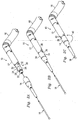
- a surgical instrument for the dissection of bone and other tissue constructed in accordance with the teachings of a first preferred embodiment is illustrated and generally identified at reference numeral 10.
- the surgical instrument 10 is shown operatively associated with a patient A for performing a craniotomy. It will become apparent to those skilled in the art that the described instrument is not limited to any particular surgical application but has utility for various applications in which it is desired to dissect bone or other tissue. Additional applications include:
- the surgical instrument 10 is illustrated to generally include a motor assembly 12, an attachment housing 14, and a surgical tool 16.
- the attachment housing 14 provides a gripping surface for use by a surgeon and also shields underlying portions of the instrument 10 during a surgical procedure.
- the surgical tool 16 is a cutting tool or dissection tool, although the type of tool is not essential to implementing the present disclosure.
- the surgical instrument 10 is shown connected to a hose assembly 18 for providing a source of pressurized fluid (e.g., air) to the motor assembly 12 and venting exhaust air away from the surgical site.
- a source of pressurized fluid e.g., air
- the surgical instrument 10 is pneumatically powered. It is further understood, however, that many of the teachings discussed herein will have equal application for an electrically powered surgical instrument.
- the motor assembly 12 includes a coupling assembly 20 with a tapered leading portion 22 and a Double D region comprising a pair of opposed and substantially parallel planar portions interrupting the cylindrical body to define two opposed substantially parallel cylindrical portions. These portions are separated by junction 24 into an axially translatable segment having cylindrical portion 26 and flat portion 28, and a rotatably translatable segment having cylindrical portion 30 and flat portion 32.
- attachment housing 14 includes an internal cavity (not shown) adapted and configured to engage coupling assembly 20 of motor assembly 12. In an initial position with first cylindrical portion 34 substantially abutting motor assembly 12, attachment indicator mark 36 is in substantial alignment with unlocked indicator mark 38 on the motor assembly.
- dissection tool 16 may be inserted into attachment housing 14 and be received in the coupling assembly 20 within motor assembly 12.
- attachment housing 14 may be rotated in the direction of arrow 40 with respect to motor assembly 12. Movement in this direction moves attachment indicator marking 36 into substantial alignment with the locked indicator marking 42 on motor assembly 12.
- Such movement also operates the coupling assembly 20 to lock dissection tool 16 into driving engagement with the internal motor.
- the motor assembly 12, attachment housing 14, and coupling assembly 20 are designed so that indicator marks 36, 38, 42 may be placed on attachment 14 and motor assembly 12 at the component level (e.g., before assembly) rather than the assembly level.
- the ability to add the indicator marks 36, 38, 42 at the component level provides a number of advantages.
- the indicator marks 36, 38, 42 (and other labeling or lettering) are typically either scratched or laser etched onto the surface of the motor assembly 12 and attachment 14. Both of these methods may produce a white or metallic marking on the anodized surface. Using scratching or laser etching, the marking can be applied at either the component level or the assembled level.
- the markings may be stamped onto a surface of a component using a force that may damage an assembled instrument.
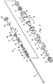
- the coupling assembly 20 includes a locking nut 66 positioned on a collet housing 44.
- the collet housing 44 has a helical slot 46 adapted to receive ball bearings 48, and a pair of apertures 50 adapted to receive alignment balls 52.
- Coupling assembly 20 further includes a housing spacer 54 and an O-ring 56 associated with posterior Double D-collet 58. Posterior Double D-collet 58 is spaced from anterior Double D-collet 62 by shim 60.
- the assembly further includes O-rings 64 and 68 and tapered nose 70.
- Coupling assembly 20 also includes hex closure sleeve 88, spring 90, rotor shaft 92, and ball bearings 94 retained in openings 96 in the rotor shaft by retaining ring 98. This internal assembly is completed by bearing 100 and lock ring 102.
- the coupling assembly 20 may be attached to the motor assembly 12 as follows. It is understood in the following example that the coupling assembly 20 is represented only by the collet housing 44 for purposes of clarity, but the coupling assembly 20 may include other components as illustrated in Fig. 3 .
- the coupling assembly 20 includes a base 104 sized for insertion into a cavity 106 of the motor assembly 12.
- the base 104 includes one or more apertures 108 that extend from the distal end of the base 104 (relative to the motor assembly 12) towards the proximal end of the base 104. However, the apertures 108 do not extend the entire length of the base 104.
- the cavity 106 in the motor assembly 12 includes one or more apertures 110 that correspond to the apertures 108 of the coupling assembly 20. Accordingly, a pin 112 may be placed in each aperture 108 of the coupling assembly 20 during before the coupling assembly 20 is inserted into the cavity 106. The pins 112 may then be aligned with the apertures 110 of the motor assembly 12 and the coupling assembly 20 may be inserted into the motor assembly 12. As the proximal end of the base 104 is not grooved, the pins 112 will not extend past the base 104. Once inserted, the pins 112 serve to align the coupling assembly 20 and the motor assembly 12 and also prevent the coupling assembly 20 from rotating within the motor assembly 12. In addition, the pin and groove arrangement provides sufficient structural strength to survive the loading created by the rotation of the tool 16 during surgery. Removal of the coupling assembly 20 will remove the pins 112.
- the coupling assembly 20 may be inserted into the motor assembly 12 and rotated to align the apertures 108, 110. When this is achieved, the matching grooves will be accessible via the origination points of the apertures 108, 110 in the distal portion of the base 104 and the motor assembly 12, respectively.
- the pins 112 may then be inserted into each pair of aligned apertures 108, 110.
- the locking nut 66 may be used to secure the coupling assembly 20 to the motor assembly 12 as follows.
- the locking nut 66 includes a plurality of threads 114 that mate with corresponding threads 116 on the motor assembly 12.
- the distal end of the base 104 has a larger diameter than the remainder of the coupling housing 44.
- the interior diameter of the locking nut 66 is sized so that the locking nut 66 may slide over the coupling assembly 20 until it reaches the base 104, which serves as a lip that prevents the locking nut 66 from further movement in the direction of the motor assembly 12.
- the threads 114 of the locking nut 66 may then engage the threads 116 of the motor assembly 12 and the locking nut 66 may be rotated until the coupling assembly 20 is secured to the motor assembly 12. Once in place, the locking nut 66 covers the exposed apertures 108 in the base 104. Accordingly, the locking nut 66 serves to both fasten the coupling assembly 20 to the motor assembly 12 and to retain the pins 112 in the apertures 108, 110.
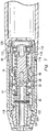
- the coupling assembly 20 of Fig. 4 is shown in cross-section and quarter-section in its assembled configuration while unlocked ( Fig. 5 ) and locked ( Figs. 6 and 7 ).
- coupling assembly 20 is shown in the unlocked position.
- Ball 48 is positioned in helical groove 46 in the proximal position.
- Ball 48 rides in ball carrier 74 and is moved by ball carrier 74 to the proximal position shown in Fig. 5 .
- ball carrier 74 urges closure sleeve 88 to compress spring 72 and permits spring 90 to expand to a relaxed position.
- closure sleeve 88 is moved away from locking ball 94 permitting it to move at least partially out of hole 96.
- o-ring 86 tends to urge locking ball 94 into hole 96.
- This arrangement provides positive positioning of locking ball 94 in hole 96 and into an aperture (not shown) in tool 16, providing tactile feedback to the user that tool 16 is properly positioned in coupling assembly 102.
- proximal Double D collet 58 may be rotated with respect to the other elements of the housing to urge ball 48 and ball carrier 74 to their distal, locking position.
- Figs. 6 and 7 shows coupling assembly 20 with proximal Double D collet 58 and balls 48 shown in the position of Fig. 5 and the remaining elements rotated approximately 90°. It will be understood that in operation of the illustrated preferred embodiment, proximal Double D collet 58 and balls 48 are moved while the other elements remain stationary. During the closure operation, as ball carrier 74 advances distally, spring 90 is compressed and spring 72 is allowed to expand.
- closure sleeve 88 As spring 72 expands, it urges closure sleeve 88 distally. Internal taper surface of closure sleeve 88 engages locking ball 94 and urges it into locking engagement with the aperture (not shown) located on the tool 16. Closure sleeve 88 continues to advance over locking ball 94 to securely hold locking ball 94 in the aperture, thereby inhibiting movement of dissection tool 16 along the longitudinal axis.
- attachment housing 14 is adapted to engage the coupling assembly 20 in an interference fit. Further, attachment housing 14 and coupling assembly 20 are configured to provide the user with tactical feedback indicating positive engagement. More specifically, attachment housing 14 includes an internal cavity 118 having a configuration substantially matching the external configuration of coupling assembly 20. The cavity 118 includes an internal annular groove 120 carrying an O-ring 122. Coupling assembly 20 defines an external annular groove 124 adapted to receive a portion of O-ring 122. Thus, it will be understood that as attachment housing 14 is advanced over coupling assembly 20, O-ring 122 will be slightly compressed into groove 120 as it engages tapered front end 22 to an expanded inner diameter.
- the compressed O-ring 122 When O-ring 122 is positioned over annular groove 124, the compressed O-ring 122 will quickly relax into a smaller inner diameter shape engaging annular groove 124 providing the user with a tactile sensation.
- a tactile sensation will include both a vibration and auditory signal, indicating that the attachment 14 is in the proper position on motor assembly 12.
- the apertures 108 of the coupling assembly 20 may be replaced by one or more protuberances.
- the protuberances may be aligned with the apertures 110 of the motor assembly 12. The protuberances may then engage the apertures 110 when the base 104 of the coupling assembly 20 is inserted into the motor assembly 12. Accordingly, the protuberances may align the coupling assembly 20 and the motor assembly 12 and may also prevent the coupling assembly 20 from rotating relative to the motor assembly 12. Furthermore, this arrangement may provide sufficient structural strength to survive the loading created by the rotation of the tool 16 during surgery.
- the relative positions that will be occupied by the motor assembly 12, attachment housing 14, and coupling assembly 20 with respect to one another may be determined before the instrument is assembled. Accordingly, alignment markings and other labeling/lettering may be applied at the component level and be in alignment when the instrument 10 is assembled.
- the locking and indexing system described above enables fabrication of housings while maintaining the alignment between any finger controls and the coupling assembly 20.
- the system securely attaches the coupling assembly 20 to the motor assembly 12 in a manner that may withstand with repeated loading caused by the rotation of the tool 16 during use.
Landscapes
- Health & Medical Sciences (AREA)
- Surgery (AREA)
- Life Sciences & Earth Sciences (AREA)
- Biomedical Technology (AREA)
- Medical Informatics (AREA)
- Orthopedic Medicine & Surgery (AREA)
- Oral & Maxillofacial Surgery (AREA)
- Engineering & Computer Science (AREA)
- Dentistry (AREA)
- Heart & Thoracic Surgery (AREA)
- Nuclear Medicine, Radiotherapy & Molecular Imaging (AREA)
- Molecular Biology (AREA)
- Animal Behavior & Ethology (AREA)
- General Health & Medical Sciences (AREA)
- Public Health (AREA)
- Veterinary Medicine (AREA)
- Surgical Instruments (AREA)
Claims (16)
- Instrument chirurgical comprenant :un ensemble de couplage (20) comprenant un logement de douille (44) pour recevoir un outil chirurgical (16), le logement de douille (44) comprenant un premier moyen de mise en prise (8) et un troisième moyen de mise en prise (124) ;un ensemble de moteur (12) comprenant un moteur interne et. pouvant fonctionner pour recevoir le logement de douille (44) dans une cavité (106) de l'ensemble de moteur (12), la cavité (106) comprenant un deuxième moyen de mise en prise (110) pouvant fonctionner pour mettre en prise le premier moyen de mise en prise (108) afin d'aligner et d'empêcher la rotation du logement de douille (44) par rapport à l'ensemble de moteur (12) ; etun élément de verrouillage rotatif (66) pouvant effectuer un mouvement de translation le long d'un axe du logement de douille (44), l'élément de verrouillage (66) pouvant fonctionner pour fixer le logement de douille (44) à l'ensemble de moteur (12),caractérisé en ce qu'il comprend en outre un logement de fixation (14) pour recevoir l'outil chirurgical (16), afin de tourner par rapport à l'ensemble de moteur (12) pour verrouiller l'outil chirurgical (16) dans l'ensemble de couplage (20) en mise en prise d'entraînement avec le moteur interne, et pour fournir une surface de préhension pouvant être saisie par un chirurgien de manière non rotative pendant une procédure chirurgicale et protéger des parties sous-jacentes de l'instrument pendant une procédure chirurgicale pendant l'opération, le logement de fixation (14) ayant un quatrième moyen de mise en prise (122) pouvant fonctionner pour mettre en prise le troisième moyen de mise en prise (124) ;dans lequel l'un parmi le troisième et le quatrième moyen de mise en prise (122, 124) est une rainure (124) et le troisième ou quatrième moyen de mise en prise résiduel est un protubérance (122).
- Instrument chirurgical selon la revendication 1, caractérisé en ce que les premier et deuxième moyens de mise en prise (108, 110) sont des première et deuxième ouvertures (108, 110) respectivement, et dans lequel l'instrument comprend en outre un élément rigide (112) pouvant fonctionner pour être monté dans une cavité formée par les première et deuxième ouvertures (108, 110).
- Instrument chirurgical selon la revendication 1, caractérisé en ce que l'un des premier et deuxième moyens de mise en prise (108, 110) est une ouverture et l'autre moyen de mise en prise est une protubérance.
- Instrument chirurgical selon la revendication 1, caractérisé en ce que le logement de fixation (14) comprend une cavité interne (118) formée sensiblement comme un extérieur du logement de douille (44).
- Instrument chirurgicale selon la revendication 1, caractérisé en ce que l'ensemble de moteur (12) et le logement de fixation (14) comprend des marques (36, 38, 42) pouvant fonctionner pour indiquer si le logement de douille (44) est verrouillé ou déverrouillé par rapport à l'outil chirurgical (16).
- Instrument chirurgical selon la revendication 1, caractérisé en ce que l'élément de verrouillage (66) comprend des filetages (114) pouvant fonctionner pour mettre en prise des filetages (116) correspondants sur l'ensemble de moteur (12).
- Instrument chirurgical selon la revendication 1, caractérisé en ce que le logement de douille (44) comprend en outre une partie de base (104) à proximité de l'ensemble de moteur (12), dans lequel la partie de base (104) peut fonctionner pour mettre en prise l'élément de verrouillage (66).
- Instrument chirurgical selon la revendication 7, caractérisé en ce qu'un diamètre externe de la partie de base (104) est supérieur à un diamètre interne de l'élément de verrouillage (66), de sorte que l'élément de verrouillage (66) ne peut pas coulisser au-delà de la partie de base (104).
- Instrument chirurgical selon la revendication 1, caractérisé en ce que le logement de fixation (14) comprend une cavité interne (118) configurée pour mettre en prise l'ensemble de couplage (20) comprenant le logement de douille (44).
- Instrument chirurgical selon la revendication 1, caractérisé en ce que la rainure (124) s'étend de manière annulaire autour d'une circonférence du logement de douille (44).
- Instrument chirurgical selon la revendication 1, caractérisé en ce que la rainure (124) est une rainure annulaire (124) s'étendant autour d'une circonférence d'une surface externe du logement de douille (44) et la protubérance (122) est un joint torique (122) positionné sur une surface interne du logement de fixation (14).
- Instrument chirurgical selon la revendication 1, caractérisé en ce que la protubérance (122) est un joint torique qui peut fonctionner pour mettre en prise la rainure (124) par la compression du joint torique.
- Procédé pour assembler un instrument chirurgical, le procédé comprenant les étapes consistant à :aligner un premier moyen de mise en prise (108, 112) d'un logement de douille (44) d'un ensemble de couplage (20) avec un deuxième moyen de mise en prise (110) correspondant sur un ensemble de moteur (12) ;insérer le logement de douille (44) dans une cavité (106) dans l'ensemble de moteur (12), moyennant quoi les premier et deuxième moyens de mise en prise (108, 110, 112) correspondants sont mis en prise pour aligner et empêcher la rotation du logement de douille par rapport à l'ensemble de moteur ; et fixer le logement de douille (44) sur l'ensemble de moteur (12) en utilisant un élément de verrouillage (66) ;fixer un logement de fixation (14) ayant une surface de préhension pouvant être saisie par un chirurgien de manière non rotative pendant une procédure chirurgicale, sur le logement de douille (44) dans une position de rotation prévisible par rapport à l'ensemble de moteur (12) en mettant en prise une cavité interne (118) du logement de fixation (14) avec une configuration externe en forme de double D de l'ensemble de couplage (20).
- Procédé selon la revendication 13, comprenant en outre l'étape consistant à faire coulisser l'élément de verrouillage (66) sur le logement de douille (44) dans la direction de l'ensemble de moteur (12).
- Procédé selon la revendication 14, comprenant en outre les étapes consistant à insérer un outil (16) dans un réceptacle dans le logement de douille (44), et faire tourner au moins une partie du logement de douille (44) pour fixer l'outil (16).
- Procédé selon la revendication 15, dans lequel l'étape consistant à faire tourner la partie du logement de douille (44) comprend l'étape consistant à faire tourner le logement de fixation (14) de sorte qu'une marque (36) sur le logement de fixation (14) s'aligne avec une marque (36, 42) correspondante sur l'ensemble de moteur (12).
Applications Claiming Priority (3)
| Application Number | Priority Date | Filing Date | Title |
|---|---|---|---|
| US10/164,880 US6780189B2 (en) | 2002-06-07 | 2002-06-07 | Surgical instrument with a collet locking and indexing system |
| US164880 | 2002-06-07 | ||
| PCT/US2003/017871 WO2003103515A1 (fr) | 2002-06-07 | 2003-06-05 | Instrument chirurgical presentant un blocage de collier et un systeme d'indexation |
Publications (3)
| Publication Number | Publication Date |
|---|---|
| EP1511432A1 EP1511432A1 (fr) | 2005-03-09 |
| EP1511432A4 EP1511432A4 (fr) | 2009-03-18 |
| EP1511432B1 true EP1511432B1 (fr) | 2016-04-13 |
Family
ID=29710303
Family Applications (1)
| Application Number | Title | Priority Date | Filing Date |
|---|---|---|---|
| EP03739050.7A Expired - Lifetime EP1511432B1 (fr) | 2002-06-07 | 2003-06-05 | Instrument chirurgical presentant un blocage de collier et un systeme d'indexation |
Country Status (3)
| Country | Link |
|---|---|
| US (2) | US6780189B2 (fr) |
| EP (1) | EP1511432B1 (fr) |
| WO (1) | WO2003103515A1 (fr) |
Families Citing this family (54)
| Publication number | Priority date | Publication date | Assignee | Title |
|---|---|---|---|---|
| US6780189B2 (en) * | 2002-06-07 | 2004-08-24 | Medtronic, Inc. | Surgical instrument with a collet locking and indexing system |
| US7559927B2 (en) * | 2002-12-20 | 2009-07-14 | Medtronic Xomed, Inc. | Surgical instrument with telescoping attachment |
| DE10358279A1 (de) * | 2003-12-11 | 2005-07-14 | Karl Storz Gmbh & Co. Kg | Medizinisches Instrument zum Schneiden von biologischen und insbesondere menschlichem Gewebe |
| US20060043684A1 (en) * | 2004-08-31 | 2006-03-02 | Medtronic, Inc. | Surgical instrument with locking element |
| US20060046856A1 (en) * | 2004-08-31 | 2006-03-02 | Medtronic, Inc. | Self-lubricating surgical instrument |
| US20060089623A1 (en) * | 2004-10-21 | 2006-04-27 | Medtronic, Inc. | Surgical instrument with wear-resistant housing and method of operating same |
| US20060259055A1 (en) * | 2005-05-13 | 2006-11-16 | Linvatec Corporation | Attachments for arthroscopic shaver handpieces |
| GB0519084D0 (en) * | 2005-09-19 | 2005-10-26 | Finsbury Dev Ltd | Tool |
| US9192397B2 (en) | 2006-12-15 | 2015-11-24 | Gmedelaware 2 Llc | Devices and methods for fracture reduction |
| EP2120734B1 (fr) | 2006-12-15 | 2015-12-02 | Gmedelaware 2 LLC | Forets pour l'implantation de stents vertébraux |
| US8460297B2 (en) * | 2007-01-05 | 2013-06-11 | Biomet 3I, Llc | Drill bit assembly for bone tissue including depth limiting feature |
| JP5264893B2 (ja) | 2007-05-17 | 2013-08-14 | プロ−デツクス・インコーポレイテツド | 手持ち式医療装置 |
| WO2010111246A1 (fr) | 2009-03-23 | 2010-09-30 | Soteira, Inc. | Dispositifs et procédés d'implantation d'endoprothèse vertébrale |
| US8581454B2 (en) * | 2010-01-11 | 2013-11-12 | Pro-Dex, Inc. | Handheld device with thermal padding |
| DE102010049244A1 (de) * | 2010-10-25 | 2012-04-26 | Dannoritzer Medizintechnik Gmbh & Co. Kg | Chirurgisches Instrument |
| CN103298420B (zh) * | 2010-11-15 | 2016-08-31 | 脊柱诊察公司 | 具有保持机构的组织去除系统 |
| US8690876B2 (en) | 2011-04-07 | 2014-04-08 | DePuy Synthes Products, LLC | Cutting burr shank configuration |
| US8801713B2 (en) * | 2011-04-07 | 2014-08-12 | DePuy Synthes Products, LLC | Surgical drill instrument with motor and locking mechanism to receive an attachment and a cutting burr |
| EP2779928B1 (fr) | 2011-11-14 | 2018-01-03 | The University of British Columbia | Système de fixation centromédullaire pour la gestion de fractures pelviennes et acétabulaires |
| US9119685B2 (en) | 2012-10-08 | 2015-09-01 | Warsaw Orthopedic, Inc. | Surgical instrument and method |
| US9572605B2 (en) | 2012-10-09 | 2017-02-21 | Warsaw Orthopedic, Inc. | Surgical instrument and method |
| WO2014075165A1 (fr) * | 2012-11-14 | 2014-05-22 | British Columbia Cancer Agency Branch | Accessoire de marteau perforateur tubulaire |
| US9320527B2 (en) * | 2013-01-18 | 2016-04-26 | Biomet Manufacturing, Llc | Quick-connect anti-rotation peg/drill bit component |
| KR102061727B1 (ko) | 2013-03-15 | 2020-01-02 | 스트리커 코포레이션 | 수술 로봇 조작기의 엔드 이펙터 |
| US9370372B2 (en) | 2013-09-04 | 2016-06-21 | Mcginley Engineered Solutions, Llc | Drill bit penetration measurement systems and methods |
| US9833244B2 (en) | 2013-11-08 | 2017-12-05 | Mcginley Engineered Solutions, Llc | Surgical saw with sensing technology for determining cut through of bone and depth of the saw blade during surgery |
| WO2015134750A1 (fr) | 2014-03-06 | 2015-09-11 | University Of British Columbia | Dispositif de fixation intramédullaire à forme adaptable |
| US9504478B2 (en) * | 2014-04-30 | 2016-11-29 | Gyrus ACMI , Inc. | Rotary tool with improved coupling assembly |
| AU2015312037A1 (en) | 2014-09-05 | 2017-03-02 | Mcginley Engineered Solutions, Llc | Instrument leading edge measurement system and method |
| WO2016061173A1 (fr) | 2014-10-14 | 2016-04-21 | Empire Technology Development Llc | Systèmes et procédés de fixation d'os intermédullaire |
| USD800906S1 (en) | 2015-03-25 | 2017-10-24 | Medtronic Ps Medical, Inc. | Surgical tool |
| USD790699S1 (en) | 2015-03-25 | 2017-06-27 | Medtronic Ps Medical, Inc. | Surgical tool |
| USD800907S1 (en) | 2015-03-25 | 2017-10-24 | Medtronic Ps Medical, Inc. | Surgical tool |
| USD782042S1 (en) | 2015-03-25 | 2017-03-21 | Medtronic Ps Medical, Inc. | Surgical tool |
| US10314610B2 (en) | 2015-03-25 | 2019-06-11 | Medtronic Ps Medical, Inc. | Slanted drive axis rotary surgical cutting tools and powered handpieces |
| US10080579B2 (en) | 2015-03-25 | 2018-09-25 | Medtronic Ps Medical, Inc. | Pin drive rotary surgical cutting tools and powered handpieces |
| US10265082B2 (en) | 2015-08-31 | 2019-04-23 | Medtronic Ps Medical, Inc. | Surgical burs |
| US10321921B2 (en) | 2015-10-27 | 2019-06-18 | Mcginley Engineered Solutions, Llc | Unicortical path detection for a surgical depth measurement system |
| WO2017075224A1 (fr) | 2015-10-27 | 2017-05-04 | Mcginley Engineered Solutions, Llc | Techniques et instruments de pose d'implants orthopédiques par rapport à des éléments osseux |
| US10206691B2 (en) * | 2015-10-29 | 2019-02-19 | Medtronic Xomed, Inc. | Method and apparatus to select vibration |
| WO2017078754A1 (fr) | 2015-11-06 | 2017-05-11 | Mcginley Engineered Solutions, Llc | Système de mesure destiné à être associé à un instrument de type fraise chirurgicale |
| USD800903S1 (en) | 2016-02-09 | 2017-10-24 | Medtronic Ps Medical, Inc. | Surgical tool |
| US11076871B2 (en) | 2016-08-31 | 2021-08-03 | Medtronic Ps Medical, Inc. | Multiple connection drive shaft |
| EP3672501B1 (fr) | 2017-08-25 | 2023-06-14 | McGinley Engineered Solutions, LLC | Détection de la mise en place d'un instrument chirurgical par rapport à des structures anatomiques |
| AU2018345760A1 (en) | 2017-10-02 | 2020-01-30 | Mcginley Engineered Solutions, Llc | Surgical instrument with real time navigation assistance |
| US10849634B2 (en) * | 2018-06-20 | 2020-12-01 | Medtronic Xomed, Inc. | Coupling portion for rotary surgical cutting systems |
| US12611240B2 (en) | 2018-10-17 | 2026-04-28 | Curvafix, Inc. | Intramedullary fixation device |
| US11832856B2 (en) | 2018-10-17 | 2023-12-05 | The University Of British Columbia | Bone-fixation device and system |
| US11529180B2 (en) | 2019-08-16 | 2022-12-20 | Mcginley Engineered Solutions, Llc | Reversible pin driver |
| US11471168B2 (en) * | 2019-12-20 | 2022-10-18 | Innovations 4 Surgery, LLC | Medical devices and related methods for transforming bone, other tissue, or material |
| US11723672B2 (en) * | 2020-03-18 | 2023-08-15 | Shukla Medical | Chuck assembly for a medical device |
| US12082825B2 (en) * | 2020-12-18 | 2024-09-10 | Medtronic, Inc. | Rotary cutting tool and powered handpiece adaptor assemblies, systems, and methods of use |
| US12588930B2 (en) | 2022-02-04 | 2026-03-31 | Curvafix, Inc. | Devices, systems, and methods of use for delivery of materials in combination with intramedullary devices |
| US12582415B2 (en) | 2022-11-16 | 2026-03-24 | Medtronic Ps Medical, Inc. | Oscillating surgical bone removal tool with fluted cutting head |
Family Cites Families (34)
| Publication number | Priority date | Publication date | Assignee | Title |
|---|---|---|---|---|
| US2719722A (en) * | 1952-10-11 | 1955-10-04 | Universal Engineering Company | Quick change tool holder |
| US2807473A (en) | 1956-02-20 | 1957-09-24 | Alfred J Kiehne | Tool mountings and release |
| US2931659A (en) * | 1958-02-12 | 1960-04-05 | Portage Double Quick Inc | Quick change tool holder |
| US3398802A (en) * | 1966-10-31 | 1968-08-27 | Aro Corp | Fluid operated drill |
| US4699550A (en) | 1984-01-31 | 1987-10-13 | Baker John W | Cranial perforator |
| US5347988A (en) | 1992-05-13 | 1994-09-20 | Linvatec Corporation | Endoscope coupler with liquid interface |
| US5222956A (en) | 1992-07-06 | 1993-06-29 | Altair Instruments, Inc. | Surgical drill collet mechanism and bur |
| US5330480A (en) | 1993-03-03 | 1994-07-19 | Codman & Shurtleff, Inc. | Surgical drill |
| US5779404A (en) | 1994-05-02 | 1998-07-14 | Jore; Matthew B. | Reversible drill/driver tool |
| US5505737A (en) | 1994-07-01 | 1996-04-09 | Midas Rex Pneumatic Tools, Inc. | Quick release coupling for a dissecting tool |
| US6270087B1 (en) | 1994-07-27 | 2001-08-07 | Mednext, Inc. | Tool shaft coupler |
| US6062575A (en) | 1994-07-27 | 2000-05-16 | Mednext, Inc. | Tool shaft coupler |
| US5490683A (en) | 1994-07-27 | 1996-02-13 | Mednext Inc. | Tool shaft coupler |
| US5634933A (en) | 1994-09-29 | 1997-06-03 | Stryker Corporation | Powered high speed rotary surgical handpiece chuck and tools therefore |
| US5601560A (en) | 1994-10-07 | 1997-02-11 | The Anspach Effort, Inc. | Tool bit for a motor driven surgical instrument |
| US5569256A (en) | 1995-02-10 | 1996-10-29 | Midas Rex Pneumatic Tools, Inc. | Surgical resection tool with a double quick release |
| US5632747A (en) | 1995-03-15 | 1997-05-27 | Osteotech, Inc. | Bone dowel cutter |
| CH690905A5 (fr) | 1995-06-14 | 2001-02-28 | Sodem Diffusion Sa | Procédé et dispositif de raccordement et instrument chirurgical pour l'entraînement d'outils rotatif interchangeables. |
| US5718582A (en) * | 1995-09-26 | 1998-02-17 | Young Dental Manufacturing | Dental tool chuck |
| US5871493A (en) * | 1995-10-31 | 1999-02-16 | Smith & Nephew Endoscopy Inc. | Surgical instrument handpiece and system |
| US5782836A (en) | 1996-07-30 | 1998-07-21 | Midas Rex Pneumatic Tools, Inc. | Resecting tool for magnetic field environment |
| US6033408A (en) | 1996-07-30 | 2000-03-07 | Midas Rex, L.P. | Resecting tool for magnetic field environment |
| US5888200A (en) | 1996-08-02 | 1999-03-30 | Stryker Corporation | Multi-purpose surgical tool system |
| US5741263A (en) | 1997-04-18 | 1998-04-21 | Midas Rex Pneumatic Tools, Inc. | Mutiple flat quick release coupling |
| US5893851A (en) | 1997-04-18 | 1999-04-13 | Midas Rex Pneumatic Tools, Inc. | Multiple chuck resecting tool |
| US5993453A (en) | 1997-10-15 | 1999-11-30 | Huntington Medical Research Institutes | Controlled-depth bone cutter |
| US5989257A (en) | 1998-03-11 | 1999-11-23 | Midas Rex L.P. | Redundant safety lock mechanism |
| US5993454A (en) | 1998-09-29 | 1999-11-30 | Stryker Corporation | Drill attachment for a surgical drill |
| US6209886B1 (en) | 1999-04-30 | 2001-04-03 | Medtronic, Inc. | Resecting tool with independent variable axial extension for tool implements and guide sleeves |
| EP2322104B1 (fr) * | 2000-02-18 | 2017-10-25 | Stryker Corporation | Poignée chirurgicale avec poussoir transférant à la fois un mouvement de rotation à un arbre de transmission de sortie et actionnant un mécanisme de blocage pour accessoire coupant |
| US7001391B2 (en) * | 2001-03-21 | 2006-02-21 | Medtronic, Inc. | Surgical instrument with rotary cutting member and quick release coupling arrangement |
| US7011661B2 (en) * | 2001-03-21 | 2006-03-14 | Medtronic, Inc. | Surgical instrument with rotary cutting member and quick release coupling arrangement |
| US7066940B2 (en) * | 2001-03-21 | 2006-06-27 | Medtronic, Inc. | Surgical instrument with rotary cutting member and quick release coupling arrangement |
| US6780189B2 (en) * | 2002-06-07 | 2004-08-24 | Medtronic, Inc. | Surgical instrument with a collet locking and indexing system |
-
2002
- 2002-06-07 US US10/164,880 patent/US6780189B2/en not_active Expired - Lifetime
-
2003
- 2003-06-05 EP EP03739050.7A patent/EP1511432B1/fr not_active Expired - Lifetime
- 2003-06-05 WO PCT/US2003/017871 patent/WO2003103515A1/fr not_active Ceased
-
2004
- 2004-04-06 US US10/818,678 patent/US20040186479A1/en not_active Abandoned
Also Published As
| Publication number | Publication date |
|---|---|
| US20040186479A1 (en) | 2004-09-23 |
| WO2003103515B1 (fr) | 2004-12-16 |
| WO2003103515A1 (fr) | 2003-12-18 |
| EP1511432A1 (fr) | 2005-03-09 |
| US20030229351A1 (en) | 2003-12-11 |
| US6780189B2 (en) | 2004-08-24 |
| EP1511432A4 (fr) | 2009-03-18 |
Similar Documents
| Publication | Publication Date | Title |
|---|---|---|
| EP1511432B1 (fr) | Instrument chirurgical presentant un blocage de collier et un systeme d'indexation | |
| EP1386587B1 (fr) | Instrument chirurgical avec organe de coupe rotatif | |
| EP1549231B1 (fr) | Instrument chirurgical dote d'un element rotatif d'incision et d'un agencement de couplage a liberation rapide | |
| US7066940B2 (en) | Surgical instrument with rotary cutting member and quick release coupling arrangement | |
| US9066729B2 (en) | Surgical instrument with telescoping attachment | |
| JP4220237B2 (ja) | 外科的装置用の万能ハンドル | |
| US8398685B2 (en) | Transbuccal plate holding cannula | |
| JP6338653B2 (ja) | 動的係止装置 | |
| US7708743B2 (en) | Apparatus and method for positioning an implant during surgery | |
| US7862553B2 (en) | Tip and shaft connection for medical device | |
| US9050110B2 (en) | Medical device | |
| WO2003024340A3 (fr) | Appareil chirurgical d'abrasion rotatif | |
| US20230301664A1 (en) | Multiple Connection Drive Shaft | |
| US9936960B2 (en) | Detachable orthopaedic reamer handle | |
| US4990038A (en) | Rotationally and axially restrained drill bit and chuck assembly | |
| AU2020236001B2 (en) | Modular orthopedic clamps | |
| US20080157488A1 (en) | Surgical coupling device | |
| EP1956965B1 (fr) | Amelioration d'appareil pour diminuer la contamination croisee | |
| JP2023554498A (ja) | 外科用器具、システム、及び方法における改善、並びにそれらに関する改善 | |
| WO2022006314A1 (fr) | Pinces orthopédiques modulaires | |
| US11786385B2 (en) | Osseointegration system | |
| WO2024025664A2 (fr) | Repères d'alignement polyédriques pour chirurgie assistée par ordinateur |
Legal Events
| Date | Code | Title | Description |
|---|---|---|---|
| PUAI | Public reference made under article 153(3) epc to a published international application that has entered the european phase |
Free format text: ORIGINAL CODE: 0009012 |
|
| 17P | Request for examination filed |
Effective date: 20041022 |
|
| AK | Designated contracting states |
Kind code of ref document: A1 Designated state(s): DE FR |
|
| RIN1 | Information on inventor provided before grant (corrected) |
Inventor name: TIDWELL, DURRELL, G. Inventor name: SHORES, REX, WESLEY |
|
| A4 | Supplementary search report drawn up and despatched |
Effective date: 20090216 |
|
| 17Q | First examination report despatched |
Effective date: 20090716 |
|
| GRAP | Despatch of communication of intention to grant a patent |
Free format text: ORIGINAL CODE: EPIDOSNIGR1 |
|
| INTG | Intention to grant announced |
Effective date: 20151013 |
|
| GRAS | Grant fee paid |
Free format text: ORIGINAL CODE: EPIDOSNIGR3 |
|
| GRAA | (expected) grant |
Free format text: ORIGINAL CODE: 0009210 |
|
| AK | Designated contracting states |
Kind code of ref document: B1 Designated state(s): DE FR |
|
| REG | Reference to a national code |
Ref country code: DE Ref legal event code: R096 Ref document number: 60348807 Country of ref document: DE |
|
| REG | Reference to a national code |
Ref country code: FR Ref legal event code: PLFP Year of fee payment: 14 |
|
| REG | Reference to a national code |
Ref country code: DE Ref legal event code: R097 Ref document number: 60348807 Country of ref document: DE |
|
| PLBE | No opposition filed within time limit |
Free format text: ORIGINAL CODE: 0009261 |
|
| STAA | Information on the status of an ep patent application or granted ep patent |
Free format text: STATUS: NO OPPOSITION FILED WITHIN TIME LIMIT |
|
| 26N | No opposition filed |
Effective date: 20170116 |
|
| REG | Reference to a national code |
Ref country code: FR Ref legal event code: PLFP Year of fee payment: 15 |
|
| REG | Reference to a national code |
Ref country code: FR Ref legal event code: PLFP Year of fee payment: 16 |
|
| PGFP | Annual fee paid to national office [announced via postgrant information from national office to epo] |
Ref country code: DE Payment date: 20200519 Year of fee payment: 18 Ref country code: FR Payment date: 20200520 Year of fee payment: 18 |
|
| REG | Reference to a national code |
Ref country code: DE Ref legal event code: R119 Ref document number: 60348807 Country of ref document: DE |
|
| PG25 | Lapsed in a contracting state [announced via postgrant information from national office to epo] |
Ref country code: DE Free format text: LAPSE BECAUSE OF NON-PAYMENT OF DUE FEES Effective date: 20220101 |
|
| PG25 | Lapsed in a contracting state [announced via postgrant information from national office to epo] |
Ref country code: FR Free format text: LAPSE BECAUSE OF NON-PAYMENT OF DUE FEES Effective date: 20210630 |