EP1511647B1 - Verschiebbare kühlerhaubenanordnung - Google Patents
Verschiebbare kühlerhaubenanordnung Download PDFInfo
- Publication number
- EP1511647B1 EP1511647B1 EP03728747A EP03728747A EP1511647B1 EP 1511647 B1 EP1511647 B1 EP 1511647B1 EP 03728747 A EP03728747 A EP 03728747A EP 03728747 A EP03728747 A EP 03728747A EP 1511647 B1 EP1511647 B1 EP 1511647B1
- Authority
- EP
- European Patent Office
- Prior art keywords
- show surface
- air bag
- surface member
- support frame
- hood assembly
- Prior art date
- Legal status (The legal status is an assumption and is not a legal conclusion. Google has not performed a legal analysis and makes no representation as to the accuracy of the status listed.)
- Expired - Lifetime
Links
- 239000000463 material Substances 0.000 claims description 14
- 229910052751 metal Inorganic materials 0.000 claims description 8
- 239000002184 metal Substances 0.000 claims description 8
- 238000004891 communication Methods 0.000 claims description 5
- 239000012530 fluid Substances 0.000 claims description 5
- 239000004753 textile Substances 0.000 claims description 5
- 229910000831 Steel Inorganic materials 0.000 claims description 4
- 239000010959 steel Substances 0.000 claims description 4
- 229910052782 aluminium Inorganic materials 0.000 claims description 3
- XAGFODPZIPBFFR-UHFFFAOYSA-N aluminium Chemical compound [Al] XAGFODPZIPBFFR-UHFFFAOYSA-N 0.000 claims description 3
- 239000004033 plastic Substances 0.000 claims description 3
- 238000000926 separation method Methods 0.000 claims description 3
- 238000006243 chemical reaction Methods 0.000 description 10
- 230000004913 activation Effects 0.000 description 3
- 238000013461 design Methods 0.000 description 3
- 238000010521 absorption reaction Methods 0.000 description 2
- 238000010276 construction Methods 0.000 description 2
- 230000009286 beneficial effect Effects 0.000 description 1
- 230000007797 corrosion Effects 0.000 description 1
- 238000005260 corrosion Methods 0.000 description 1
- 238000011161 development Methods 0.000 description 1
- 230000003292 diminished effect Effects 0.000 description 1
- 230000002708 enhancing effect Effects 0.000 description 1
- 239000004744 fabric Substances 0.000 description 1
- 239000011152 fibreglass Substances 0.000 description 1
- 239000011810 insulating material Substances 0.000 description 1
- 239000003973 paint Substances 0.000 description 1
- 230000002093 peripheral effect Effects 0.000 description 1
- 239000007787 solid Substances 0.000 description 1
- 238000005728 strengthening Methods 0.000 description 1
- 238000013519 translation Methods 0.000 description 1
- 238000013022 venting Methods 0.000 description 1
- 238000003466 welding Methods 0.000 description 1
Images
Classifications
-
- B—PERFORMING OPERATIONS; TRANSPORTING
- B60—VEHICLES IN GENERAL
- B60R—VEHICLES, VEHICLE FITTINGS, OR VEHICLE PARTS, NOT OTHERWISE PROVIDED FOR
- B60R21/00—Arrangements or fittings on vehicles for protecting or preventing injuries to occupants or pedestrians in case of accidents or other traffic risks
- B60R21/34—Protecting non-occupants of a vehicle, e.g. pedestrians
- B60R21/36—Protecting non-occupants of a vehicle, e.g. pedestrians using airbags
Definitions
- This invention relates to a hood assembly for use in an automotive vehicle, and more particularly to a hood assembly incorporating inflatable elements for expansion during an impact event.
- hood structures may be opened so as to permit access to an underlying compartment which may store the engine of the vehicle in vehicles incorporating a forward engine design or a luggage storage compartment in vehicles which incorporate a rear engine design.
- the hood portion of the vehicle is typically formed from a relatively thin sheet of metal such as thin gauge steel which may be molded to the appropriate contour corresponding to the overall vehicle body design.
- the exterior of the hood portion which constitutes the show surface thereof is typically coated with one or more coats of primer and paint for enhancing both the aesthetic character and the corrosion resistance of the underlying material.
- a support structure such as a contoured plate with stamped rib supports typically extends across the underside of the hood portion so as to provide a degree of dimensional stability to the structure.
- the hood In the event of a collision, it may be desirable for the hood to have the ability to absorb energy thereby dissipating the force to which persons involved in the collision event may otherwise be subjected.
- the desirability of such energy absorbing character may be particularly important if the collision involves direct contact between the hood and a pedestrian, bicycle operator, motorcycle operator, or other persons at the exterior of the vehicle.
- substantially fixed elements underlying the hood such as batteries, engine components and the like may give rise to hard surfaces across the expanse of the hood which may resist deformation and corresponding energy absorption.
- structural elements peripheral to the hood such as fenders and the so called “scuttle area" immediately below the windshield may also provide relatively poor energy absorption.
- JP-A-10 152 018 discloses a vehicle hood composed of two panels with an airbag therebetween.
- an automotive hood assembly which comprises at least one plastically deformable extensible tether element operatively connecting the exterior show surface member and the support frame wherein said at least one plastically deformable extensible tether element is plastically deformed to an increased operative length as the exterior show surface member is projected away from the support frame such that said at least one plastically deformable extensible tether element thereafter supports the exterior show surface member at an elevated position relative to the support frame while maintaining an operative connection between the support frame and the exterior show surface member.
- the automobile hood assembly includes a relatively thin deformable exterior defining an outer show surface and an underlying support structure. Disposed between the exterior member and the underlying support structure is an arrangement of one or more inflatable cushions in fluid communication with one or more gas emitting inflators. Upon receipt of an activation signal from a sensor, inflation gas is introduced into the cushion which inflates outwardly away from the underlying support structure thereby causing a corresponding outward deformation of the exterior hood structure.
- the arrangement of gas accepting cushions may be such that the inflated expansion provides a degree of coverage across surfaces of the vehicle outboard of the exterior hood member.
- An arrangement of one or more extensible tethering elements preferably limits the degree of outward expansion of the exterior portion of the hood. The forced outward movement of the exterior portion of the hood assembly gives rise to an extended surface profile thereby leading to an enhanced ability on the part of the hood assembly to absorb energy through collapsible deformation upon impact by a pedestrian or other foreign body.
- a plurality of inflatable expansible cushions may be utilized so as to provide deformation forces across different portions of the hood assembly.
- a single inflatable cushion may also be utilized if desired.
- one or more of the expansible cushions utilized may be configured to expand to positions outboard of the exterior hood surface upon inflation thereby providing inflated coverage across regions such as the windshield, the scuttle area directly beneath the windshield, the forward pillar structures adjacent to the windshield and the fenders disposed along the sides of the hood assembly.
- the inflatable cushion may remain entirely beneath the exterior hood surface if desired.
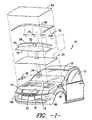
- FIG. 1 there is illustrated an automotive vehicle 10 including a passenger compartment 12 for housing one or more occupants (not shown).
- the vehicle 10 also includes a forward body portion designated generally as 14 which extends in leading relation away from the passenger compartment 12 towards a front bumper 16.
- a storage compartment 18 At the interior of the forward body portion 14 is a storage compartment 18 which may be used to house an engine or the like.
- a hood assembly is disposed in overlying relation to the storage compartment 18.
- the hood assembly includes an interior support frame 22 such as a framework of structural metal strut members, a stamped metal plate structure with integral strengthening ribs or the like disposed in overlying relation to the storage compartment.
- the interior support frame may be covered across its underside by a insulating material such as a molded non-woven textile or the like as will be well known to those of skill in the art so as to dampen noise and vibration from underlying engine components.
- reaction plate member 24 disposed at a position above the interior support frame 22 is a reaction plate member 24.
- the reaction plate member is preferably formed of thin gauge steel, aluminum or other metal, although other materials such as fiberglass, plastic or the like may also be used if desired.
- the reaction plate member 24 provides a substantially uniform reaction surface across the interior support frame 22 during inflation of an overlying cushion assembly 26 in a manner to be described further hereinafter. It is contemplated that the reaction plate member 24 may be eliminated in the event that the interior support frame 22 is of either a solid configuration without internal openings or otherwise provides a substantially uniform support surface for reaction against the overlying air bag assembly 26.
- the air bag assembly 26 includes a first cushion element 28 and a second cushion element 30 in fluid communication with one another through a translation conduit 32.
- the first cushion element 28 and the second cushion element 30 may be inflated by inflation gas transmitted through a common gas receiver 34 in fluid communication with one or more inflators 36 which may be stored at convenient locations within the vehicle 10.
- the gas receiver 34 may be of a simple configuration such as a box structure having one or more inlets and a common outlet feeding into the air bag assembly 26.
- first cushion element 28 and the second cushion element 30 are illustrated as being interconnected and being inflated from a common gas source, it is likewise contemplated that the first cushion element 28 and the second cushion element 30 may be separate from one another and linked to one or more dedicated inflators if desired.
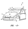
- the first cushion element 28 is normally stored below the windshield 15 at a generally rearward location of the forward body portion 14. Upon inflation, the first cushion element 28 is projected outwardly across the so-called scuttle area between the windshield 15 and the hood assembly so as to at least partially cover the scuttle area and the windshield 15 as shown in FIG. 2 .
- the second cushion element 30 is configured so as to inflate across an interior portion of the reaction plate member 24 in a forward relation relative to the first cushion element 28. It is contemplated that the width of the second cushion element 30 may be such that upon inflation portions of the second cushion element 30 may project outwardly in at least partial covering relation to portions of the fenders of the vehicle 10.
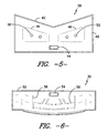
- first cushion element 28 includes a generally concave upper edge 40 which is projected upwardly across the windshield 15 so as to provide enhanced coverage at the lateral sides of the windshield 15 along the forward structural pillars 42.
- Inflation gas is introduced through a mouth opening 44 in sealed relation with the conduit 32 as illustrated in FIG. 1 .
- the first cushion element 28 may be of a sewn construction formed from panels of textile material adjoined along perimeter edges by perimeter seams 45 such as sewn seams, welded seams such as RF (radio frequency), ultrasonic welded seams, and the like. It is likewise contemplated that the panels of material forming the first cushion element 28 may be adjoined to one another in a pattern at the interior of the first cushion element 28 so as to form a pattern of zero length tethers 46 which limit the expansion of the first cushion element 28 at the interior. It is contemplated that by limiting the expansion of the first cushion element 28 an enhanced area of coverage may be provided.
- venting elements 50 may be disposed at selected locations across the first cushion element 28 so as to allow for the controlled dissipation of inflation gas upon impact by a person or other structure. While the first cushion element 28 is illustrated as being formed from two panels of material adjoined completely around the perimeter, it is likewise contemplated that such a structure may be formed from a single panel of material which is folded upon itself and sealed around the open edges.
- the second cushion element 30 may include a mouth opening 54 for introduction of inflation gas from the gas receiver 34 as shown in FIG. 1 .
- the second cushion element 30 may be formed from panels of materials such as textile fabrics, films, and the like which are joined together by perimeter seams 55 such as sewn seams, welded seams including RF welded seams and/or ultrasonic welded seams and the like.
- a pattern of zero length tethers 56 may be disposed across the interior of the second cushion element 30 thereby joining the panels of material forming the second cushion element 30 together at the location of such zero length tethers 56.
- the second cushion element 30 preferably projects away from the windshield 15 towards the front bumper 16. While the second cushion element 30 may extend across substantially the entire forward body portion 14, it is likewise contemplated that the second cushion element 30 may project across a diminished portion of the forward body portion 14 if desired. While the second cushion element 28 is illustrated as being formed from two panels of material adjoined completely around the perimeter, it is likewise contemplated that such a structure may be formed from a single panel of material which is folded upon itself and sealed around the open edges.
- the presence of the cushion elements 28, 30 above the interior support frame 22 causes the exterior show surface member 60 to be forced upwardly away from the interior support frame 22 upon the inflation of the cushion elements ( FIG. 2 ).
- the outward projection of the exterior show surface member 60 gives rise to an energy absorbing impact surface which may engage a pedestrian thrown upon the hood during a collision event.
- the exterior show surface member 60 will preferably maintain some degree of attachment relative to the interior support frame 22 following outward expansion. Maintaining such attachment is believed to aid in the development of a defined impact surface across the show surface member 60 during activation and reduces the chance of the show surface member being lost.
- the exterior show surface member 60 may be operatively connected to the interior support frame 22 by one or more extensible tether elements 70 which extend to a controlled degree upon the application of tension as force is generated across the exterior show surface member 60 by the cushion elements 28, 30.
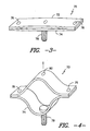
- One embodiment of an extensible tether element 70 is illustrated in FIGS. 3 and 4 .
- the extensible tether element 70 is constructed from an upper tether plate 72 and a lower tether plate 74.
- the upper tether plate 72 and the lower tether plate 74 are fixedly adjoined to one another at their ends by spot welds 76 or other attachment structures such as screws, bolts, and the like.
- An attachment element 78 such as a screw, bolt, snap attachment or the like extends away from the lower tether plate 74 for secure attachment relative to the interior support frame 22. As illustrated, the attachment element 78 is located inboard of the spot welds 76 and does not engage the upper tether plate 72.
- the upper tether plate 72 is operatively connected to the exterior show surface member 60 by an interior spot weld 80 which is preferably disposed in substantially opposing relation to the attachment element 78.
- an interior spot weld 80 which is preferably disposed in substantially opposing relation to the attachment element 78.
- one or both of the tether plates may be formed from a plastically deformable material such as steel, aluminum or other metal or the like such that the extensible tether element will maintain its shape after elongation. That is, once the plates have been deformed they will hold their configuration until an adequate collapsing force is applied to restore the initial configuration.
- Such structural integrity following deformation may be beneficial in holding the exterior show surface away from the underlying frame until such time as it collapses under the force of impact by a pedestrian or other object outside the vehicle.
- an interior carrier member 82 of metal, plastic, or the like may be glued or otherwise adhered to the bottom of the exterior show surface member 60.
- the extensible tether element 70 may thereafter be welded or otherwise secured to the interior carrier member 82 such as by welding the upper tether plate 72 to the bottom of the interior carrier member 82 at the interior spot weld 80.
- the desired operative connection may be achieved without giving rise to any attachment markings across the exterior show surface member 60.
- the extensible tether element 70 will be located at a position so as to not interfere with the extension of the cushion elements 28, 30.
- a series of extensible tether elements 70 is arranged at a position immediately over the intersection between the first cushion element 28 and the second cushion element 30 so as to permit the attachment elements 78 to pass immediately behind the rear edge of the second cushion element 30 and through the reaction plate member 24 for attachment at the interior support frame 22.
- an actual or impending impact with a person or exterior object may be sensed by one or more sensors 86.
- the sensors 86 thereafter transmit an activation signal to the inflators 36 resulting in the generation of a high pressure inflation gas which is transmitted into the cushion elements 28, 30 which make up the air bag assembly 26.
- the cushion elements are forced into an expanded configuration thereby causing the first cushion element 28 to expand outwardly from beneath the rear of the exterior show surface member 60 and across the windshield 15.
- the second cushion element 30 expands beneath the exterior show surface member 60 while being supported by the reaction plate member 24.
- the expansion force is translated to the exterior show surface member 60 so as to cause the exterior show surface member 60 project outwardly away from the underlying interior support frame 22.
- this outward projection is nonetheless limited by the presence of one or more expansible tether elements 70 which maintain an operative connection between the interior support frame 22 and the exterior show surface member 60.
- the exterior show surface member 60 is thereafter held in a raised energy absorbing condition by the expanded cushion elements in combination with the plastically deformed tether elements 70.
- first cushion element 28 and second cushion element 30 may be operated independently of one another.
- first cushion element 28 or the second cushion element 30 may be eliminated entirely such that the assembly incorporates only a single cushion element if desired.
Landscapes
- Engineering & Computer Science (AREA)
- Mechanical Engineering (AREA)
- Superstructure Of Vehicle (AREA)
- Seal Device For Vehicle (AREA)
Claims (11)
- Einem Staufach (18) in einem Kraftfahrzeug (10) übergelagerte Kühlerhaubenanordnung, wobei die Kühlerhaubenanordnung umfasst:Außenflächenelement (60);Unter dem Außenflächenelement (60) angeordneten Stützrahmen (22);Mindestens eine das Außenflächenelement (60) und den Stützrahmen (22) wirkend miteinander verbindende plastisch deformierbare, ausdehnbare Halterung (70); undMindestens ein aufblasbares Luftkissen (30) umfassende, unmittelbar zwischen Stützrahmen (22) und Außenflächenelement (60) angeordnete Airbag-Anordnung (26), wobei sich das mindestens eine Luftkissen (30) in laufender Kommunikation mit mindestens einer selektiv aktivierbaren Gas emittierenden Aufblasvorrichtung (36) befindet, sodass die mindestens eine selektiv aktivierbare Gas emittierende Aufblasvorrichtung (36) Gas in das mindestens eine aufblasbare Luftkissen (30) leitet und dieses mindestens eine aufblasbare Luftkissen (30) zu einem expandierten Profil aufgeblasen wird, sodass mindestens ein Teil des Außenflächenelements (60) dadurch vom Stützrahmen (22) abgehoben wird, um eine Aufprall absorbierende Fläche zu bilden und wobei die mindestens eine plastisch deformierbare, ausdehnbare Halterung (70) plastisch zu einer erhöhten Wirkungslänge deformiert wird, wenn das Außenflächenelement (60) über den Stützrahmen (22) hinaus ausgedehnt wird, solchermaßen, dass die plastisch deformierbare, ausdehnbare Halterung (70) danach das Außenflächenelement (60) auf einer im Verhältnis zum Stützrahmen (22) erhöhten Position hält, dabei jedoch die Wirkverbindung zwischen Stützrahmen (22) und Außenflächenelement (60) aufrechterhält.
- Kühlerhaubenanordnung gemäß Anspruch 1, wobei die Airbag-Anordnung (26) ein erstes Luftkissen (28), welches dazu angepasst ist, aufgeblasen und von unter dem Außenflächenelement (60) zumindest teilweise über eine Windschutzscheibe (15) vom Außenflächenelement (60) aus nach hinten disponiert zu werden, sowie mindestens ein zweites Luftkissen (30) umfasst, welches dazu angepasst ist, aufgeblasen und in einem Bereich unter dem Außenflächenelement (60) disponiert zu werden.
- Kühlerhaubenanordnung gemäß Anspruch 2, wobei das erste Luftkissen (28) eine stark konkave Oberkante (40) aufweist.
- Kühlerhaubenanordnung gemäß Anspruch 3, wobei das erste Luftkissen (28) Textilgewebe enthält.
- Kühlerhaubenanordnung gemäß Anspruch 2, wobei das zweite Luftkissen (30), wenn es aufgeblasen ist, über eine größere Breite verfügt als das Außenflächenelement (60), sodass nach dem Aufblasen die Seiten des zweiten Luftkissens (30) mindestens teilweise über die benachbarten Kotflügelbereiche des Fahrzeugs (10) hinausragen.
- Kühlerhaubenanordnung gemäß Anspruch 5, wobei das zweite Luftkissen (30) Textilgewebe enthält.
- Kühlerhaubenanordnung gemäß Anspruch 1, des Weiteren ein an der Unterseite des Außenflächenelements (60) angebrachtes Trägerelement (82) umfassend, wobei das Trägerelement (82) eine Anbringungsfläche für besagte mindestens eine plastisch deformierbare Halterung (70) bildet.
- Kühlerhaubenanordnung gemäß Anspruch 1, wobei die Halterung (70) eine obere (72) und eine untere Platte (74) aufweist, wobei die obere (72) und die untere Platte (74) an in einem bestimmten Abstand zueinander angeordneten Halterungspunkten (76) solchermaßen aneinander angebracht sind, dass die obere Platte (72) entlang der zwischen den in einem bestimmten Abstand zueinander angeordneten Halterungspunkten (76) befindlichen Bereichen von der unteren Platte (74) wegbewegt werden kann, und wobei die obere Platte (72) wirkend an einem ersten, zwischen den besagten, in einem bestimmten Abstand zueinander angeordneten Halterungspunkten (76) liegenden Halterungspunkt (80) an dem Außenflächenelement (60) angebracht ist, und wobei die untere Platte (74) durch eine zwischen den in einem bestimmten Abstand zueinander angeordneten Halterungspunkten (76) befindliche Anbringungsvorrichtung (78) im Verhältnis zum Stützrahmen (78) in einem im Wesentlichen festen Abstand solchermaßen befestigt ist, dass die obere Platte (72) von der unteren Platte (74) entlang eines zwischen den in einem bestimmten Abstand zueinander angeordneten Halterungspunkten (76) liegenden Bereichs voneinander wegbewegt werden, wenn sich das Außenflächenelement (60) vom Stützrahmen (22) wegbewegt, und zumindest entweder die untere (74) und/oder die obere Platte (72) bei einer derartigen Trennung plastisch deformiert wird.
- Kühlerhaubenanordnung gemäß Anspruch 8, wobei zumindest die obere Platte (72) und/oder die untere Platte (74) Metall enthält.
- Kühlerhaubenanordnung gemäß Anspruch 9, wobei dieses Metall aus einer Stahl und Aluminium enthaltenden Gruppe gewählt wird.
- Kühlerhaubenanordnung gemäß Anspruch 2, wobei sich das erste Luftkissen (28) und das zweite Luftkissen (30) in laufender Kommunikation miteinander und mit mindestens einer selektiv aktivierbaren Gas emittierenden Aufblasvorrichtung (36) befinden.
Applications Claiming Priority (3)
| Application Number | Priority Date | Filing Date | Title |
|---|---|---|---|
| US150130 | 2002-05-16 | ||
| US10/150,130 US6712169B2 (en) | 2002-05-16 | 2002-05-16 | Displaceable automotive hood assembly |
| PCT/US2003/014275 WO2003097398A1 (en) | 2002-05-16 | 2003-05-08 | Displaceable automotive hood assembly |
Publications (3)
| Publication Number | Publication Date |
|---|---|
| EP1511647A1 EP1511647A1 (de) | 2005-03-09 |
| EP1511647A4 EP1511647A4 (de) | 2005-11-16 |
| EP1511647B1 true EP1511647B1 (de) | 2008-10-22 |
Family
ID=29419180
Family Applications (1)
| Application Number | Title | Priority Date | Filing Date |
|---|---|---|---|
| EP03728747A Expired - Lifetime EP1511647B1 (de) | 2002-05-16 | 2003-05-08 | Verschiebbare kühlerhaubenanordnung |
Country Status (5)
| Country | Link |
|---|---|
| US (1) | US6712169B2 (de) |
| EP (1) | EP1511647B1 (de) |
| AT (1) | ATE411928T1 (de) |
| DE (1) | DE60324277D1 (de) |
| WO (1) | WO2003097398A1 (de) |
Families Citing this family (31)
| Publication number | Priority date | Publication date | Assignee | Title |
|---|---|---|---|---|
| JP2003095044A (ja) * | 2001-09-06 | 2003-04-03 | Takata Corp | 外面展開型エアバッグ装置 |
| ITTV20020103A1 (it) * | 2002-09-09 | 2004-03-10 | Plastal Spa | Struttura di frontale per veicolo, del tipo con controllo |
| DE10341368A1 (de) * | 2003-09-03 | 2005-04-07 | Takata-Petri Ag | Sicherheitseinrichtung an einem Kraftfahrzeug zum Schutz von Fußgängern und Radfahrern |
| GB0407047D0 (en) * | 2004-03-29 | 2004-04-28 | Nygaard Jens H S | Passenger carrying road vehicle and a strengthening member for a passenger carrying road vehicle |
| US20050269829A1 (en) * | 2004-06-04 | 2005-12-08 | Oivind Nilsrud | Dual function under-hood liner |
| DE102004029757A1 (de) * | 2004-06-19 | 2006-01-05 | Adam Opel Ag | Kraftfahrzeug mit aktivem Fußgängerschutz |
| FR2873087B1 (fr) * | 2004-07-16 | 2006-09-22 | Univ Pasteur | Dispositif actif de securite comportant une plaque amortissante recouvrant le pare-brise d'un vehicule en cas de collision avec un pieton |
| JP2006056327A (ja) * | 2004-08-18 | 2006-03-02 | Nippon Plast Co Ltd | 衝撃吸収フード |
| DE102004047863B4 (de) * | 2004-10-01 | 2006-07-13 | Daimlerchrysler Ag | Sicherheitsvorrichtung für ein Kraftfahrzeug |
| JP4621119B2 (ja) * | 2005-11-18 | 2011-01-26 | 本田技研工業株式会社 | 衝突物保護装置 |
| US7413049B2 (en) * | 2006-10-18 | 2008-08-19 | Antolin Asp, Inc. | Pedestrian protection hood lifting systems |
| US20080114516A1 (en) * | 2006-11-15 | 2008-05-15 | Jackson David M | Inflatable pusher |
| WO2008151459A2 (de) * | 2007-06-14 | 2008-12-18 | Max Horlacher | Sicherheitsfahrzeug |
| US7997375B2 (en) * | 2009-04-17 | 2011-08-16 | Tony Shaw | Vehicle hood apparatus |
| US8811247B2 (en) * | 2010-06-25 | 2014-08-19 | Cisco Technology, Inc. | Automating radio enablement to facilitate power saving |
| DE102011119564A1 (de) * | 2011-11-26 | 2013-05-29 | GM Global Technology Operations LLC (n. d. Gesetzen des Staates Delaware) | Gassack für ein Fußgängerschutzsystem und damit ausgestattetes Kraftfahrzeug |
| WO2013131771A1 (de) * | 2012-03-05 | 2013-09-12 | Bayerische Motoren Werke Aktiengesellschaft | FUßGÄNGERSCHUTZWORRICHTUNG FÜR EIN KRAFTFAHRZEUG |
| EP2743145B1 (de) * | 2012-12-12 | 2017-04-19 | Volvo Car Corporation | Sicherheitsanordnung für ein Kraftfahrzeug |
| US8768574B1 (en) | 2013-02-22 | 2014-07-01 | Ventra Group, Inc. | Pedestrian protection vehicle hood hinge assembly |
| GB2516699B (en) * | 2013-07-30 | 2017-05-03 | Jaguar Land Rover Ltd | Airbag device for a vehicle bonnet |
| US9889806B2 (en) * | 2013-10-21 | 2018-02-13 | GM Global Technology Operations LLC | Light weight bus bars, methods of manufacture thereof and articles comprising the same |
| KR101460723B1 (ko) * | 2013-11-26 | 2014-11-12 | 현대모비스 주식회사 | 차량의 보행자 보호용 에어백 모듈 |
| KR101640247B1 (ko) * | 2014-08-29 | 2016-07-15 | 현대모비스 주식회사 | 보행자 보호용 에어백장치 |
| CN206374708U (zh) * | 2016-11-14 | 2017-08-04 | 京东方科技集团股份有限公司 | 一种汽车 |
| DE102017004044A1 (de) * | 2017-04-26 | 2018-10-31 | GM Global Technology Operations LLC (n. d. Ges. d. Staates Delaware) | Kraftfahrzeugkarosserie mit Airbaganordnung im Bereich eines Windlaufs |
| CN106976485B (zh) * | 2017-05-05 | 2023-02-24 | 黄河科技学院 | 一种具有保护功能的汽车发动机罩 |
| US20190084521A1 (en) * | 2017-09-18 | 2019-03-21 | Ford Global Technologies, Llc | Vehicle airbag assembly |
| US10800458B2 (en) | 2019-02-14 | 2020-10-13 | Ford Global Technologies, Llc | Energy absorbing seal for a vehicle |
| US11097785B2 (en) | 2019-07-19 | 2021-08-24 | Volvo Car Corporation | Automobile hood for decoupled pedestrian safety and durability |
| JP2021138290A (ja) * | 2020-03-05 | 2021-09-16 | 本田技研工業株式会社 | エアバッグ配置構造 |
| US12447924B2 (en) * | 2023-05-02 | 2025-10-21 | Ford Global Technologies, Llc | Airbag inflatable under vehicle hood |
Family Cites Families (29)
| Publication number | Priority date | Publication date | Assignee | Title |
|---|---|---|---|---|
| US2854281A (en) | 1955-11-14 | 1958-09-30 | Benjamin I Cassin | Safety shield for automobiles |
| US3037809A (en) | 1958-02-20 | 1962-06-05 | Praha Anton | Vehicle comprising a protective device for the occupants |
| US3650542A (en) | 1968-07-22 | 1972-03-21 | Nissan Motor | Motor vehicle safety device |
| FR2272866B1 (de) | 1974-05-30 | 1978-12-22 | Peugeot & Renault | |
| DE2711338C3 (de) | 1977-03-16 | 1981-10-01 | Hermann Prof. Dr.-Ing. 1000 Berlin Appel | Kraftfahrzeug mit Einrichtungen zum Dämpfen des Aufpralls eines Fußgängers |
| US4171140A (en) | 1977-10-27 | 1979-10-16 | Suga Toshihisa | Automotive safeguard for protecting occupants |
| DE2814107A1 (de) | 1978-04-01 | 1979-10-04 | Volkswagenwerk Ag | Sicherheitseinrichtung zum schutz von fussgaengern |
| JPH03186448A (ja) | 1989-12-15 | 1991-08-14 | Takata Kk | パッセンジャー用エアバッグ |
| JPH04193643A (ja) | 1990-11-28 | 1992-07-13 | Masahiko Ito | 搭乗者のフロントガラスへの衝突ガード装置 |
| US5653464A (en) | 1995-10-05 | 1997-08-05 | Automotive Technologies International Inc. | Airbag system with self shaping airbag |
| DE4232658A1 (de) | 1992-09-29 | 1994-03-31 | Trw Repa Gmbh | Aufblasbarer Gassack für ein Rückhaltesystem in Fahrzeugen |
| JP2888116B2 (ja) | 1993-10-15 | 1999-05-10 | トヨタ自動車株式会社 | ピラーエアバッグ装置 |
| JP3005627B2 (ja) | 1993-10-15 | 2000-01-31 | トヨタ自動車株式会社 | 転落防止エアバッグ装置 |
| DE19615744C1 (de) | 1996-04-20 | 1997-06-05 | Daimler Benz Ag | Kraftfahrzeug mit mehreren Karosserieteilen |
| JP3840711B2 (ja) | 1996-11-26 | 2006-11-01 | 日産自動車株式会社 | 衝撃吸収フード |
| JPH10217903A (ja) | 1997-02-06 | 1998-08-18 | Honda Motor Co Ltd | 車体用衝撃吸収体 |
| JPH10315908A (ja) | 1997-05-15 | 1998-12-02 | Akimitsu Iizuka | ボンネット型車両用エアバッグ装置 |
| US5931498A (en) | 1997-08-21 | 1999-08-03 | Milliken & Company | Simplified air bag configuration |
| DE19745873A1 (de) | 1997-10-17 | 1999-04-22 | Volkswagen Ag | Airbageinrichtung für ein Kraftfahrzeug |
| US6019390A (en) | 1998-04-30 | 2000-02-01 | Milliken & Company | Multiple panel airbag |
| JP3687418B2 (ja) * | 1998-06-26 | 2005-08-24 | 日産自動車株式会社 | 跳ね上げフード |
| GB9904266D0 (en) * | 1999-02-24 | 1999-04-21 | Automotive Dev Specialists Ltd | Inflatable protection apparatus |
| SE514218C2 (sv) * | 1999-05-25 | 2001-01-22 | Volvo Personvagnar Ab | Anordning vid gångjärn till motorhuvar på personbilar |
| US6293362B1 (en) * | 1999-07-09 | 2001-09-25 | Honda Giken Kogyo Kabushiki Kaisha | Vehicle hood apparatus |
| US6386623B1 (en) | 2000-06-19 | 2002-05-14 | Delphi Technologies, Inc. | Automotive hood of inflatable character |
| US6467563B1 (en) * | 2000-06-19 | 2002-10-22 | Delphi Technologies, Inc. | Windshield frame air bag for pedestrian protection |
| US6530449B2 (en) * | 2000-07-19 | 2003-03-11 | Honda Giken Kogyo Kabushiki Kaisha | Hood assembly for vehicle |
| US6513617B2 (en) * | 2000-07-26 | 2003-02-04 | Honda Giken Kogyo Kabushiki Kaisha | Vehicle hood apparatus |
| JP3711847B2 (ja) * | 2000-07-27 | 2005-11-02 | 日産自動車株式会社 | 車両用エアバッグ装置 |
-
2002
- 2002-05-16 US US10/150,130 patent/US6712169B2/en not_active Expired - Fee Related
-
2003
- 2003-05-08 AT AT03728747T patent/ATE411928T1/de not_active IP Right Cessation
- 2003-05-08 EP EP03728747A patent/EP1511647B1/de not_active Expired - Lifetime
- 2003-05-08 WO PCT/US2003/014275 patent/WO2003097398A1/en not_active Ceased
- 2003-05-08 DE DE60324277T patent/DE60324277D1/de not_active Expired - Lifetime
Also Published As
| Publication number | Publication date |
|---|---|
| EP1511647A4 (de) | 2005-11-16 |
| EP1511647A1 (de) | 2005-03-09 |
| WO2003097398A1 (en) | 2003-11-27 |
| US20030213635A1 (en) | 2003-11-20 |
| US6712169B2 (en) | 2004-03-30 |
| ATE411928T1 (de) | 2008-11-15 |
| DE60324277D1 (de) | 2008-12-04 |
Similar Documents
| Publication | Publication Date | Title |
|---|---|---|
| US6712169B2 (en) | Displaceable automotive hood assembly | |
| US6467563B1 (en) | Windshield frame air bag for pedestrian protection | |
| US5069480A (en) | Air bag retainer assembly | |
| US5324072A (en) | Side impact air bag | |
| US6874811B2 (en) | Expandable rigid knee airbag system | |
| JP3043738U (ja) | 屋根取付け型エアバッグ | |
| EP2213527B1 (de) | Fahrzeug mit einer fussgänger-airbag-vorrichtung | |
| US5752717A (en) | Inflatable metal bladders for automobile passenger protection | |
| US6386623B1 (en) | Automotive hood of inflatable character | |
| JP4291821B2 (ja) | 車両用フードエアバッグ装置 | |
| US6880666B2 (en) | Automotive outboard air bag system | |
| US6382660B1 (en) | Air bag assembly | |
| US20010054811A1 (en) | Inflatable knee bolster | |
| WO2003053751A1 (en) | Vehicle frontal airbag system | |
| US6409210B1 (en) | Integrated side air curtain and inflator overhead system | |
| EP1156950A1 (de) | Aufblasbare schutzeinrichtung | |
| WO1992000207A1 (en) | Air bag device for assistant-driver's seat | |
| US5419583A (en) | Air bag device for an automotive vehicle | |
| US20020089152A1 (en) | Dual plane head protection air bag system | |
| JP2004189215A (ja) | 自動車の乗員のための安全装置 | |
| JP2001063511A (ja) | 車両のサイドエアバッグ装置 | |
| JP2003306098A (ja) | 車両外置きエアバック装置 | |
| JP4494949B2 (ja) | 車両外置きエアバッグ装置 | |
| JP2006159971A (ja) | 車両外置きエアバッグ装置 | |
| JP2003252162A (ja) | 車両用乗員膝部保護装置 |
Legal Events
| Date | Code | Title | Description |
|---|---|---|---|
| PUAI | Public reference made under article 153(3) epc to a published international application that has entered the european phase |
Free format text: ORIGINAL CODE: 0009012 |
|
| 17P | Request for examination filed |
Effective date: 20041216 |
|
| AK | Designated contracting states |
Kind code of ref document: A1 Designated state(s): AT BE BG CH CY CZ DE DK EE ES FI FR GB GR HU IE IT LI LU MC NL PT RO SE SI SK TR |
|
| A4 | Supplementary search report drawn up and despatched |
Effective date: 20051004 |
|
| RIC1 | Information provided on ipc code assigned before grant |
Ipc: 7B 60R 21/34 A |
|
| GRAP | Despatch of communication of intention to grant a patent |
Free format text: ORIGINAL CODE: EPIDOSNIGR1 |
|
| GRAS | Grant fee paid |
Free format text: ORIGINAL CODE: EPIDOSNIGR3 |
|
| GRAA | (expected) grant |
Free format text: ORIGINAL CODE: 0009210 |
|
| AK | Designated contracting states |
Kind code of ref document: B1 Designated state(s): AT BE BG CH CY CZ DE DK EE ES FI FR GB GR HU IE IT LI LU MC NL PT RO SE SI SK TR |
|
| REG | Reference to a national code |
Ref country code: GB Ref legal event code: FG4D |
|
| REG | Reference to a national code |
Ref country code: CH Ref legal event code: EP |
|
| REG | Reference to a national code |
Ref country code: IE Ref legal event code: FG4D |
|
| REF | Corresponds to: |
Ref document number: 60324277 Country of ref document: DE Date of ref document: 20081204 Kind code of ref document: P |
|
| NLV1 | Nl: lapsed or annulled due to failure to fulfill the requirements of art. 29p and 29m of the patents act | ||
| PG25 | Lapsed in a contracting state [announced via postgrant information from national office to epo] |
Ref country code: AT Free format text: LAPSE BECAUSE OF FAILURE TO SUBMIT A TRANSLATION OF THE DESCRIPTION OR TO PAY THE FEE WITHIN THE PRESCRIBED TIME-LIMIT Effective date: 20081022 Ref country code: BG Free format text: LAPSE BECAUSE OF FAILURE TO SUBMIT A TRANSLATION OF THE DESCRIPTION OR TO PAY THE FEE WITHIN THE PRESCRIBED TIME-LIMIT Effective date: 20090122 Ref country code: ES Free format text: LAPSE BECAUSE OF FAILURE TO SUBMIT A TRANSLATION OF THE DESCRIPTION OR TO PAY THE FEE WITHIN THE PRESCRIBED TIME-LIMIT Effective date: 20090202 |
|
| PG25 | Lapsed in a contracting state [announced via postgrant information from national office to epo] |
Ref country code: SI Free format text: LAPSE BECAUSE OF FAILURE TO SUBMIT A TRANSLATION OF THE DESCRIPTION OR TO PAY THE FEE WITHIN THE PRESCRIBED TIME-LIMIT Effective date: 20081022 Ref country code: PT Free format text: LAPSE BECAUSE OF FAILURE TO SUBMIT A TRANSLATION OF THE DESCRIPTION OR TO PAY THE FEE WITHIN THE PRESCRIBED TIME-LIMIT Effective date: 20090323 Ref country code: NL Free format text: LAPSE BECAUSE OF FAILURE TO SUBMIT A TRANSLATION OF THE DESCRIPTION OR TO PAY THE FEE WITHIN THE PRESCRIBED TIME-LIMIT Effective date: 20081022 Ref country code: FI Free format text: LAPSE BECAUSE OF FAILURE TO SUBMIT A TRANSLATION OF THE DESCRIPTION OR TO PAY THE FEE WITHIN THE PRESCRIBED TIME-LIMIT Effective date: 20081022 |
|
| PG25 | Lapsed in a contracting state [announced via postgrant information from national office to epo] |
Ref country code: BE Free format text: LAPSE BECAUSE OF FAILURE TO SUBMIT A TRANSLATION OF THE DESCRIPTION OR TO PAY THE FEE WITHIN THE PRESCRIBED TIME-LIMIT Effective date: 20081022 Ref country code: DK Free format text: LAPSE BECAUSE OF FAILURE TO SUBMIT A TRANSLATION OF THE DESCRIPTION OR TO PAY THE FEE WITHIN THE PRESCRIBED TIME-LIMIT Effective date: 20081022 Ref country code: EE Free format text: LAPSE BECAUSE OF FAILURE TO SUBMIT A TRANSLATION OF THE DESCRIPTION OR TO PAY THE FEE WITHIN THE PRESCRIBED TIME-LIMIT Effective date: 20081022 Ref country code: RO Free format text: LAPSE BECAUSE OF FAILURE TO SUBMIT A TRANSLATION OF THE DESCRIPTION OR TO PAY THE FEE WITHIN THE PRESCRIBED TIME-LIMIT Effective date: 20081022 |
|
| PLBE | No opposition filed within time limit |
Free format text: ORIGINAL CODE: 0009261 |
|
| STAA | Information on the status of an ep patent application or granted ep patent |
Free format text: STATUS: NO OPPOSITION FILED WITHIN TIME LIMIT |
|
| PG25 | Lapsed in a contracting state [announced via postgrant information from national office to epo] |
Ref country code: SE Free format text: LAPSE BECAUSE OF FAILURE TO SUBMIT A TRANSLATION OF THE DESCRIPTION OR TO PAY THE FEE WITHIN THE PRESCRIBED TIME-LIMIT Effective date: 20090122 Ref country code: IT Free format text: LAPSE BECAUSE OF FAILURE TO SUBMIT A TRANSLATION OF THE DESCRIPTION OR TO PAY THE FEE WITHIN THE PRESCRIBED TIME-LIMIT Effective date: 20081022 Ref country code: CZ Free format text: LAPSE BECAUSE OF FAILURE TO SUBMIT A TRANSLATION OF THE DESCRIPTION OR TO PAY THE FEE WITHIN THE PRESCRIBED TIME-LIMIT Effective date: 20081022 |
|
| 26N | No opposition filed |
Effective date: 20090723 |
|
| PG25 | Lapsed in a contracting state [announced via postgrant information from national office to epo] |
Ref country code: SK Free format text: LAPSE BECAUSE OF FAILURE TO SUBMIT A TRANSLATION OF THE DESCRIPTION OR TO PAY THE FEE WITHIN THE PRESCRIBED TIME-LIMIT Effective date: 20081022 |
|
| PG25 | Lapsed in a contracting state [announced via postgrant information from national office to epo] |
Ref country code: MC Free format text: LAPSE BECAUSE OF NON-PAYMENT OF DUE FEES Effective date: 20090531 |
|
| REG | Reference to a national code |
Ref country code: CH Ref legal event code: PL |
|
| PG25 | Lapsed in a contracting state [announced via postgrant information from national office to epo] |
Ref country code: CH Free format text: LAPSE BECAUSE OF NON-PAYMENT OF DUE FEES Effective date: 20090531 Ref country code: LI Free format text: LAPSE BECAUSE OF NON-PAYMENT OF DUE FEES Effective date: 20090531 |
|
| PG25 | Lapsed in a contracting state [announced via postgrant information from national office to epo] |
Ref country code: IE Free format text: LAPSE BECAUSE OF NON-PAYMENT OF DUE FEES Effective date: 20090508 |
|
| PG25 | Lapsed in a contracting state [announced via postgrant information from national office to epo] |
Ref country code: GR Free format text: LAPSE BECAUSE OF FAILURE TO SUBMIT A TRANSLATION OF THE DESCRIPTION OR TO PAY THE FEE WITHIN THE PRESCRIBED TIME-LIMIT Effective date: 20090123 |
|
| PG25 | Lapsed in a contracting state [announced via postgrant information from national office to epo] |
Ref country code: LU Free format text: LAPSE BECAUSE OF NON-PAYMENT OF DUE FEES Effective date: 20090508 |
|
| REG | Reference to a national code |
Ref country code: DE Ref legal event code: R081 Ref document number: 60324277 Country of ref document: DE Owner name: VOLKSWAGEN AG, DE Free format text: FORMER OWNER: DELPHI TECHNOLOGIES, INC., VOLKSWAGEN AG, , US Effective date: 20110415 Ref country code: DE Ref legal event code: R081 Ref document number: 60324277 Country of ref document: DE Owner name: AUTOLIV DEVELOPMENT AB, SE Free format text: FORMER OWNER: DELPHI TECHNOLOGIES, INC., VOLKSWAGEN AG, , US Effective date: 20110415 Ref country code: DE Ref legal event code: R081 Ref document number: 60324277 Country of ref document: DE Owner name: VOLKSWAGEN AG, DE Free format text: FORMER OWNERS: DELPHI TECHNOLOGIES, INC., TROY, MICH., US; VOLKSWAGEN AG, 38440 WOLFSBURG, DE Effective date: 20110415 Ref country code: DE Ref legal event code: R081 Ref document number: 60324277 Country of ref document: DE Owner name: AUTOLIV DEVELOPMENT AB, SE Free format text: FORMER OWNERS: DELPHI TECHNOLOGIES, INC., TROY, MICH., US; VOLKSWAGEN AG, 38440 WOLFSBURG, DE Effective date: 20110415 |
|
| PG25 | Lapsed in a contracting state [announced via postgrant information from national office to epo] |
Ref country code: HU Free format text: LAPSE BECAUSE OF FAILURE TO SUBMIT A TRANSLATION OF THE DESCRIPTION OR TO PAY THE FEE WITHIN THE PRESCRIBED TIME-LIMIT Effective date: 20090423 |
|
| PG25 | Lapsed in a contracting state [announced via postgrant information from national office to epo] |
Ref country code: TR Free format text: LAPSE BECAUSE OF FAILURE TO SUBMIT A TRANSLATION OF THE DESCRIPTION OR TO PAY THE FEE WITHIN THE PRESCRIBED TIME-LIMIT Effective date: 20081022 |
|
| PG25 | Lapsed in a contracting state [announced via postgrant information from national office to epo] |
Ref country code: CY Free format text: LAPSE BECAUSE OF FAILURE TO SUBMIT A TRANSLATION OF THE DESCRIPTION OR TO PAY THE FEE WITHIN THE PRESCRIBED TIME-LIMIT Effective date: 20081022 |
|
| PGFP | Annual fee paid to national office [announced via postgrant information from national office to epo] |
Ref country code: FR Payment date: 20120326 Year of fee payment: 10 |
|
| REG | Reference to a national code |
Ref country code: FR Ref legal event code: TQ Owner name: VOLKSWAGEN AKTIENGESELLSCHAFT, DE Effective date: 20120716 Ref country code: FR Ref legal event code: TQ Owner name: AUTOLIV DEVELOPMENT AB, SE Effective date: 20120716 |
|
| PGFP | Annual fee paid to national office [announced via postgrant information from national office to epo] |
Ref country code: GB Payment date: 20120515 Year of fee payment: 10 |
|
| GBPC | Gb: european patent ceased through non-payment of renewal fee |
Effective date: 20130508 |
|
| REG | Reference to a national code |
Ref country code: FR Ref legal event code: ST Effective date: 20140131 |
|
| PG25 | Lapsed in a contracting state [announced via postgrant information from national office to epo] |
Ref country code: GB Free format text: LAPSE BECAUSE OF NON-PAYMENT OF DUE FEES Effective date: 20130508 |
|
| PG25 | Lapsed in a contracting state [announced via postgrant information from national office to epo] |
Ref country code: FR Free format text: LAPSE BECAUSE OF NON-PAYMENT OF DUE FEES Effective date: 20130531 |
|
| PGFP | Annual fee paid to national office [announced via postgrant information from national office to epo] |
Ref country code: DE Payment date: 20150306 Year of fee payment: 13 |
|
| REG | Reference to a national code |
Ref country code: DE Ref legal event code: R119 Ref document number: 60324277 Country of ref document: DE |
|
| PG25 | Lapsed in a contracting state [announced via postgrant information from national office to epo] |
Ref country code: DE Free format text: LAPSE BECAUSE OF NON-PAYMENT OF DUE FEES Effective date: 20161201 |