EP1511652B1 - Procédé d'enregistrement d'une collision ou d'un risque de collision - Google Patents
Procédé d'enregistrement d'une collision ou d'un risque de collision Download PDFInfo
- Publication number
- EP1511652B1 EP1511652B1 EP03729876A EP03729876A EP1511652B1 EP 1511652 B1 EP1511652 B1 EP 1511652B1 EP 03729876 A EP03729876 A EP 03729876A EP 03729876 A EP03729876 A EP 03729876A EP 1511652 B1 EP1511652 B1 EP 1511652B1
- Authority
- EP
- European Patent Office
- Prior art keywords
- vehicle
- collision
- recording
- distance
- state
- Prior art date
- Legal status (The legal status is an assumption and is not a legal conclusion. Google has not performed a legal analysis and makes no representation as to the accuracy of the status listed.)
- Expired - Lifetime
Links
- 238000000034 method Methods 0.000 title claims description 12
- 230000001960 triggered effect Effects 0.000 claims description 4
- 230000000007 visual effect Effects 0.000 claims description 2
- 238000001514 detection method Methods 0.000 description 44
- 238000012360 testing method Methods 0.000 description 8
- 238000013459 approach Methods 0.000 description 6
- 230000003287 optical effect Effects 0.000 description 6
- 238000005259 measurement Methods 0.000 description 5
- 238000012544 monitoring process Methods 0.000 description 3
- 230000008901 benefit Effects 0.000 description 2
- 230000001413 cellular effect Effects 0.000 description 2
- 230000001419 dependent effect Effects 0.000 description 2
- 239000000446 fuel Substances 0.000 description 2
- 230000001133 acceleration Effects 0.000 description 1
- 230000009471 action Effects 0.000 description 1
- 230000004888 barrier function Effects 0.000 description 1
- 230000005540 biological transmission Effects 0.000 description 1
- 230000008859 change Effects 0.000 description 1
- 230000003247 decreasing effect Effects 0.000 description 1
- 230000005764 inhibitory process Effects 0.000 description 1
- 239000004973 liquid crystal related substance Substances 0.000 description 1
- 230000008569 process Effects 0.000 description 1
- 238000005070 sampling Methods 0.000 description 1
- 230000035939 shock Effects 0.000 description 1
- 230000011664 signaling Effects 0.000 description 1
- 230000005236 sound signal Effects 0.000 description 1
Images

Classifications
-
- G—PHYSICS
- G07—CHECKING-DEVICES
- G07C—TIME OR ATTENDANCE REGISTERS; REGISTERING OR INDICATING THE WORKING OF MACHINES; GENERATING RANDOM NUMBERS; VOTING OR LOTTERY APPARATUS; ARRANGEMENTS, SYSTEMS OR APPARATUS FOR CHECKING NOT PROVIDED FOR ELSEWHERE
- G07C5/00—Registering or indicating the working of vehicles
- G07C5/08—Registering or indicating performance data other than driving, working, idle, or waiting time, with or without registering driving, working, idle or waiting time
- G07C5/0841—Registering performance data
- G07C5/0875—Registering performance data using magnetic data carriers
- G07C5/0891—Video recorder in combination with video camera
Definitions
- the invention is based on a method for detecting a collision or a collision risk with an approaching vehicle according to the preamble of the main claim.
- a parking aid is already known from DE 199 37 939 A1, in which measuring devices for determining the distance between the motor vehicle and a detected object are arranged at least at the rear and / or front region of a motor vehicle. When falling below a predetermined minimum distance between the motor vehicle and the object, a signaling device is activated. This will alert someone who controls the approaching object to the collision. If a collision nevertheless occurs, it is quite common in practice that the driver of the vehicle that has damaged the parked vehicle, either consciously or unconsciously, leaves the scene of the accident, so that the owner of the parked vehicle himself may be responsible incurred damage to his vehicle. In order to be able to prosecute the driver of the vehicle that caused the damage, the vehicle owner is then dependent on testimonials or his own observation of his vehicle.
- a vehicle monitoring system in which a camera constantly monitors the vehicle environment. In case of damage to the vehicle, a warning is transmitted.
- a device for optical recording of the vehicle environment in which an optical recording device is activated by means of at least one proximity sensor at least whenever at least one proximity sensor detects the intrusion of an object in the vicinity of the vehicle environment.
- the detection device according to the invention with the features of the main claim has the advantage that in a collision, in particular a parked vehicle in which the detection device is installed, and an approaching vehicle, the approaching vehicle is optically detected. As a result, a later identification of the approaching vehicle is possible, e.g. via its license plate. In all likelihood, the owner of the vehicle in which the detection device is installed can thus locate the damage to his vehicle. In addition, the accident can be documented and, if necessary, reconstructed.
- the detection device connects to a radio interface, so that individual images or image sequences of the first vehicle can be transmitted via the radio interface.
- images of the approaching vehicle in the event of a collision can not only be transmitted to the owner of the vehicle, e.g. be forwarded via a mobile phone, but also to a police station, which is automatically informed about the accident. Instead of a transmission of image data, only information about a completed accident can be forwarded.
- a locating device e.g. a position determination unit by means of GPS (Global Positioning System)
- GPS Global Positioning System
- measuring devices for determining the distance between the measuring device and the approaching vehicle, so that, on the one hand, as early as possible a warning to the driver of the approaching Vehicle can be issued and on the other hand, the camera device for optical detection of the first vehicle is activated before a collision. As a result, the entire approaching process to the vehicle can be documented so that later the entire course of the accident can be reconstructed.
- the operating state during driving serves e.g. to determine the distances to obstacles for the vehicle and e.g. to facilitate a parking in a parking space.
- the measurement frequency and / or the number of operated sensors is reduced, which form the means for contactless detection of a distance, so that the power consumption of the detection device is reduced compared to the operating state.
- a loudspeaker and / or a microphone are provided corresponding to the detection device, e.g. the user of the mobile telephone unit immediately make contact with the driver of the first vehicle.
- the owner of the detection device immediately disassociates further action with the driver of the first vehicle, e.g. can call the insurance number of the driver of the first vehicle.
- the detection device can be operated independently of a power grid or a vehicle battery become. Even with longer life of a vehicle in which the detection device is arranged, the vehicle battery is not unnecessarily burdened by the operation of the detection device. A permanent operation even with longer parking times can thus be ensured.
- a separate voltage supply unit for example a fuel cell or a solar cell.
- FIG. 1 shows a plan view of a motor vehicle with a schematic representation of a detection device according to the invention.
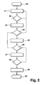
- FIG. 2 shows a method according to the invention for operating a detection device according to the invention.
- the detection device according to the invention can be operated both in mobile units, as well as stationary.
- a stationary use is possible, for example, in an arrangement at a driveway or in a parking garage, wherein it is detected when a vehicle collides with a wall, a barrier or an entrance gate.
- the detection unit is part of an environment detection system of the motor vehicle, which serves to detect obstacles in the surroundings of the vehicle while driving.
- the present detection device is used in particular to detect a collision in a parked vehicle, but can also detect collisions during driving, for example, a rear-end collision. Can be advantageous For this purpose sensors are included, which serve to trigger an airbag.
- FIG. 1 shows a plan view of a first motor vehicle 24 approaching a second motor vehicle 1, the second motor vehicle 1 having a detection device according to the invention.
- sensors for non-contact distance measurement are arranged to obstacles.
- On the right side of the vehicle 6 and on the left side of the vehicle 7 each two sensors 8 and 9 are arranged.
- the sensors 4, 5, 8, 9 can each use the same or different measuring principles.
- ultrasonic sensors, radar sensors, lidar sensors or video sensors can preferably be used.
- the sensors are connected via a data bus 10 to a central unit 11, which evaluates the sensor signals of the sensors 4, 4 ', 5, 5', 8, 9.
- a first camera device 12 for monitoring the front vehicle compartment in front of the motor vehicle 1 and a second camera device 13 for monitoring the rear vehicle compartment behind the motor vehicle 1 are connected, which also serve to monitor the vehicle sides.
- the camera devices 12, 13 are preferably designed as video sensors, which are already arranged in the motor vehicle 1 for the surroundings detection of the vehicle, for example for tracking control of the vehicle.
- the camera devices 12, 13 may also be embodied as stereo cameras, which additionally also enable a distance measurement to the approaching vehicle.
- the camera devices 12, 13 may be the approach of the first Detect vehicle 24 in the form of individual images or as image sequences.
- the image data is captured as a video sequence.
- the camera apparatus is preferably equipped with a wide-angle lens, preferably with a so-called fish-eye lens, in order to be able to detect the largest possible area.
- the camera devices 12, 13 can also be arranged such that they can pivot in such a way that, depending on a detected distance signal, the camera device can be swiveled in the direction of the obstacle.
- the central unit is connected to an acoustic output unit 14, which is preferably designed as a vehicle horn. Furthermore, a loudspeaker unit which is suitable for a voice output can also be arranged.
- the central unit 11 is further connected to a display unit 15 which is arranged in front of the driver and which serves to display further vehicle-relevant variables, for example the vehicle speed. After a collision, the driver is shown after boarding or starting the engine in the display unit 15 that a collision has previously occurred. By the note is avoided that the driver does not notice the damage and possibly drives with a traffic-insecure vehicle or he can not later reconstruct, where the accident took place.
- the central unit 11 is further connected to a memory device 16 in which the image data captured by the camera devices 12, 13 are stored.
- the image data is generally only stored volatile. However, if a collision is detected, the image of the respective associated camera device at which a predetermined time before and after the collision Vehicle side of the collision is done, stored in the memory device 16.
- the memory device 16 is preferably arranged at a hidden point of the vehicle so that a driver of the approaching vehicle can not find the memory device 16 readily in the motor vehicle 1, and he is not tempted to remove the memory device 16 from the motor vehicle 1 ,
- the central unit 11 is connected to a radio interface 17 via which a mobile radio link 29 can preferably be set up to form a mobile radio network 18.
- a service center 19 is also connected.
- the service center is implemented as a police station in which images of the collision immediately accumulate.
- the central unit 11 is further connected to a locating device 20, via which the position of the motor vehicle 1 is detected and likewise can be transmitted via the mobile radio connection to the service center 19.
- the mobile network further preferably informs the owner of the vehicle about a further mobile radio connection 21 and his mobile radio unit 22.
- the mobile radio links 21, 29 are preferably designed as UMTS connections.
- a first vehicle 24 approaches the front side 2 of the motor vehicle 1.
- the sensor 4 'detects too small a distance to the approaching vehicle 24th
- a predetermined distance is undershot and detected by the central unit 11, this activates a first warning light 25 and a second warning light 26, depending on the vehicle side of the approach of a vehicle.
- this may e.g. a high-beam light source are used, at the back e.g. the brake lights, especially the higher arranged, third brake light.
- the hazard warning system 27 is activated for a predetermined period of time. The collision is detected in a first embodiment via the sensors 4, 4 ', namely, when a very small, predetermined minimum distance is exceeded.
- at least one further sensor 28 is connected to the central unit 11 in the motor vehicle 1.
- the further sensor 28 is e.g. as an acceleration sensor that detects a shock applied to the parked vehicle.
- the user of the mobile radio unit 22 in a preferred embodiment via a microphone 30 disposed on the vehicle and the acoustic output unit 14 in telephone connection with the driver of the first vehicle 24 occur and discuss the accident with this.
- the central unit 11 is connected to the vehicle battery 32.
- a switching unit 33 is also provided, which can be selectively connected to a power supply unit 34 assigned to the central unit 11.
- the central unit 11 also supplies the remaining components of the detection device with an operating voltage.
- the switching unit 33 is set so that during a driving operation a Power supply via the Anlagenakkumulator 32 takes place, while after stopping the vehicle, the switching unit 33 automatically switches to the central unit 11 associated power supply unit 34.
- the voltage supply unit 34 is designed in a preferred embodiment as a solar cell unit, which enables a self-powered power supply of the central unit 11 with sufficient light irradiation.
- the voltage source assigned to the central unit 11 can alternatively be embodied as a fuel cell.
- FIG. 2 shows a method for operating the detection device according to the invention and explained with reference to FIG.
- an initialization step 40 the method according to the invention is started after the vehicle has been turned off. Thereafter, the detection device switches to a sleep mode, wherein the switching unit 33 switches in the preferred embodiment to a power supply by means of the power supply unit 34. Further, in the sleep mode, the sampling frequency of the distance between the sensors 4, 4 ', 8, 9 to the vehicle surroundings is lowered from traveling. In a further embodiment, not all sensors but, possibly also in change, only individual sensors, for example the middle sensors 4 ', 5' are operated. As a result, the power consumption of the detection device is lowered. In a first detection step 41, the distance to possible obstacles is determined during operation in the sleep mode.
- first test step 42 it is checked whether an obstacle is approaching the vehicle.
- an obstacle is approaching the vehicle.
- the absolute distance to the obstacle can be taken into account.
- Standing obstacles eg a wall on which the vehicle is parked, can thereby be excluded.
- the operating mode of the detection device is activated and branching takes place to the second detection step 43, in which at least on the vehicle side for which the collision risk has been determined, an operation of all sensors with an increased measurement frequency he follows.
- a second test step 44 it is then checked whether the risk of collision still exists. If there is no longer a risk of collision, the system branches back to the idle state and thus to the first detection step 41. If, on the other hand, the collision risk persists or if the distance of an approaching vehicle is lower or its speed has increased, then a first warning step 45 is branched.
- the first warning step 45 only an optical warning by means of the hazard warning system 27 and / or the warning lights 25, 26, for example by means of the taillights, the brake light or the flashlight.
- the warning takes place by flashing the corresponding light sources. If the obstacle continues to approach the sensors, the frequency of the flashing can be increased until the operation of the light sources, for example, falls below a distance of 30 cm into a continuous light.
- the first warning step 45 is followed by a third test step 46, in which it is checked whether the obstacle to the Motor vehicle 1 has approximated. If this is not the case, then branching back to the second test step 44.
- a second warning step 47 is branched in which, in addition to the visual warning signals to the driver of the approaching vehicle, acoustic signals are also output, preferably by means of an acoustic output unit designed as a vehicle horn, eg a repeating audio signal, whose repetition rate increases with increasing approach of the first vehicle 24, or a continuous tone whose frequency is increased with increasing approach of the first vehicle 24.
- an acoustic output unit designed as a vehicle horn, eg a repeating audio signal, whose repetition rate increases with increasing approach of the first vehicle 24, or a continuous tone whose frequency is increased with increasing approach of the first vehicle 24.
- the image data is first stored volatile in the memory device 16.
- the second warning step 47 is followed by a fourth test step 48, in which it is checked whether a collision has occurred. If this is not the case, then branching back to the third test step 46. However, if a collision with the approaching vehicle is detected either via the sensors 4, 5, 8, 9 or via the further sensor for collision detection 28, a further branching takes place to a third detection step 49.
- the image data captured by the camera devices 12, 13 is non-volatile written in the memory device 16.
- a radio connection to the mobile radio network 18 is established via the radio interface 17. Via the mobile radio network 18, the mobile radio unit 22 of the user of the motor vehicle 1 and / or the service center 19 can now be informed of the collision.
- image data from the collision may be transmitted over the cellular network 18 to the cellular unit 22 and / or the service center 19. Further, in the third Detection step 49 determines the position of the vehicle via the location device 20 and transmitted via the mobile network 18 in a preferred embodiment. Here only information about the accident needs to be transmitted. In a preferred embodiment, image data from the crash is also transmitted to the service center. Depending on the severity of the accident, which can be determined on the basis of the transmitted images, the fire brigade and / or an emergency service can be contacted from there.
- the vehicle horn 14 and the warning lamps 25, 26 are activated for a predetermined period of time so that the driver of the approaching vehicle is informed of the collision. Furthermore, an acoustic text output in the form of an announcement of the words "crash” or "crash” via the loudspeaker 14 can additionally take place.
- the display unit 15 indicates that a collision has taken place in the meantime.
- the liquid crystal display of the display unit 15, not shown in FIG. 1, can also be used to retrieve the images of the collision stored in the memory device 16.
- a telephone connection between the motor vehicle 1 and the mobile radio unit 22 and / or the service center 19 can be established via the mobile radio connection 29, so that the driver of the approaching vehicle 24 can make contact with the owner of the vehicle or with the service center 19 via this telephone connection ,
- a microphone is arranged on the motor vehicle 1 in a suitable manner, the acoustic signals can be recorded by the driver of the vehicle.
- the central unit 11 switches the detection device in an end step 50 back to an initial state, so that possible further collisions can be detected again.
Landscapes
- Engineering & Computer Science (AREA)
- Multimedia (AREA)
- Physics & Mathematics (AREA)
- General Physics & Mathematics (AREA)
- Traffic Control Systems (AREA)
- Dc-Dc Converters (AREA)
- Emergency Alarm Devices (AREA)
Claims (6)
- Procédé d'enregistrement d'une collision ou d'un risque de collision d'un véhicule, notamment qui se gare, avec un premier véhicule approchant (24), selon lequel une collision ou un risque de collision avec le premier véhicule (24) est détecté par au moins un capteur (4, 4', 5, 5', 8, 9, 28) et un dispositif de caméra (12, 13) saisit optiquement le premier véhicule (24), un enregistrement du premier véhicule (24) au moyen du dispositif de caméra (12, 13) étant déclenché par le capteur (4, 4', 5, 5', 8, 9, 28) pour détecter la collision ou le risque de collision,
caractérisé en ce que
le dispositif de détection est relié à une interface radio (17), et une image enregistrée par la caméra (12, 13) est transmise par l'interface radio (17), par l'intermédiaire d'un réseau de téléphonie mobile (18), à une unité de téléphonie mobile (22) et/ou à une centrale de service (19). - Procédé selon la revendication 1,
caractérisé en ce que
des moyens optiques et/ou acoustiques (14, 25, 26) sont déclenchés avec la collision ou le risque de collision pour avertir le conducteur du premier véhicule (24). - Procédé selon l'une quelconque des revendications précédentes,
caractérisé en ce qu'
il comprend des moyens (4, 4', 5, 5', 8, 9) pour détecter sans contact une distance entre les moyens de détection de distance sans contact et le premier véhicule, des moyens (14, 25, 26) pour avertir de façon optique et/ou acoustique le conducteur du premier véhicule, et les moyens d'avertissement sont déclenchés lorsque la distance par rapport au premier véhicule (24) descend en dessous d'une limite prédéterminée. - Procédé selon la revendication 3,
caractérisé en ce que
les moyens (4, 4', 5, 5', 8, 9) pour détecter une distance sans contact fonctionnent dans un premier état et dans un deuxième état, dont le premier état est un état de fonctionnement et le deuxième état est un état de repos, et dans l'état de repos, seule une partie (4', 5') des moyens de détection sans contact fonctionne. - Procédé selon l'une quelconque des revendications précédentes,
caractérisé en ce que
le dispositif de détection est relié à un dispositif de mémoire (16) pour stocker des données d'image du premier véhicule. - Procédé selon l'une quelconque des revendications précédentes,
caractérisé en ce que
le dispositif de détection est relié à une unité d'alimentation électrique (34) associée au dispositif de détection.
Applications Claiming Priority (3)
| Application Number | Priority Date | Filing Date | Title |
|---|---|---|---|
| DE10223123 | 2002-05-24 | ||
| DE2002123123 DE10223123A1 (de) | 2002-05-24 | 2002-05-24 | Erfassungsvorrichtung |
| PCT/DE2003/001486 WO2003099610A1 (fr) | 2002-05-24 | 2003-05-09 | Dispositif de saisie |
Publications (2)
| Publication Number | Publication Date |
|---|---|
| EP1511652A1 EP1511652A1 (fr) | 2005-03-09 |
| EP1511652B1 true EP1511652B1 (fr) | 2006-08-09 |
Family
ID=29414130
Family Applications (1)
| Application Number | Title | Priority Date | Filing Date |
|---|---|---|---|
| EP03729876A Expired - Lifetime EP1511652B1 (fr) | 2002-05-24 | 2003-05-09 | Procédé d'enregistrement d'une collision ou d'un risque de collision |
Country Status (4)
| Country | Link |
|---|---|
| EP (1) | EP1511652B1 (fr) |
| AU (1) | AU2003204307B2 (fr) |
| DE (2) | DE10223123A1 (fr) |
| WO (1) | WO2003099610A1 (fr) |
Families Citing this family (34)
| Publication number | Priority date | Publication date | Assignee | Title |
|---|---|---|---|---|
| DE10310698A1 (de) * | 2003-03-12 | 2004-09-23 | Valeo Schalter Und Sensoren Gmbh | Optisches Erfassungssystem für Kraftfahrzeuge |
| DE10349210B4 (de) * | 2003-10-23 | 2014-02-13 | Robert Bosch Gmbh | System und Verfahren zum vorausschauenden Detektieren eines potentiellen Unfallobjektes im Kraftfahrzeugbereich |
| DE102004004546C5 (de) * | 2004-01-23 | 2020-02-20 | Volkswagen Ag | Verfahren und Vorrichtung zur Reduzierung von Unfallfolgen für Personen in einem Kraftfahrzeug |
| DE102004004669A1 (de) * | 2004-01-30 | 2005-12-29 | Rubin Geier | Videosensorisches Kfz-Unfall- und Schadenhergangserfassungssystem |
| DE102004027693A1 (de) * | 2004-04-08 | 2005-10-27 | Daimlerchrysler Ag | Verfahren zum Steuern von Insassenrückhaltemitteln und Steuereinheit für Insassenrückhaltemittel in einem Fahrzeug |
| JP4657765B2 (ja) * | 2005-03-09 | 2011-03-23 | 三菱自動車工業株式会社 | ノーズビューシステム |
| DE102006012336B4 (de) * | 2005-04-21 | 2017-10-12 | Volkswagen Ag | Kraftfahrzeug-Umgebungserfassungssystem und Verfahren zum Erfassen einer Bild-Information |
| DE102008018671B4 (de) | 2008-04-14 | 2023-07-06 | Volkswagen Ag | Berührungsdetektionseinrichtung für ein Kraftfahrzeug |
| DE102008021554A1 (de) * | 2008-04-30 | 2009-11-05 | Schleicher, Günter | Vorrichtung und Verfahren zur automatisierten Unfallmeldung |
| DE102008039606A1 (de) * | 2008-08-25 | 2010-03-04 | GM Global Technology Operations, Inc., Detroit | Kraftfahrzeug mit einem Abstandssensor und einem Bilderfassungssystem |
| DE102008048163A1 (de) * | 2008-09-19 | 2010-03-25 | Continental Automotive Gmbh | System zur Kollisionsaufzeichnung |
| DE102010062141B4 (de) * | 2010-11-29 | 2023-08-17 | Bayerische Motoren Werke Aktiengesellschaft | Fahrzeug mit mindestens einem Umfelderfassungssystem |
| DE102011014914A1 (de) * | 2011-03-24 | 2012-09-27 | Volkswagen Aktiengesellschaft | Verfahren und Vorrichtung zur Archivierung des Blinkers bei Erkennung eines herannahenden Fahrzeugs bei einem Ausparkvorgang |
| ITSA20110020A1 (it) * | 2011-08-30 | 2013-03-01 | Salvatore Bove | Sistema e metodo per certificare sinistri subiti da un veicolo. |
| DE102012004185B4 (de) | 2012-03-05 | 2024-10-24 | Heinrich Henryk Bastian | Warnvorrichtung zur Signalisierung eines Gefährdungszustandes |
| DE102012212612A1 (de) * | 2012-07-18 | 2014-05-22 | Bayerische Motoren Werke Aktiengesellschaft | Bestimmen eines Aufenthaltsortes eines Benutzers eines mobilen Endgeräts bezogen auf ein Fahrzeug |
| DE102012218412A1 (de) * | 2012-10-10 | 2014-06-12 | Bayerische Motoren Werke Aktiengesellschaft | Verfahren und Vorrichtung zum Betreiben eines Kraftfahrzeugs |
| DE102013001578B4 (de) * | 2013-01-30 | 2018-06-21 | Heinrich Henryk Bastian | Auslösesensor für eine Warnlichtvorrichtung |
| GB2511508A (en) * | 2013-03-04 | 2014-09-10 | Neal Maurice Rose | Apparatus and method for protecting a parked vehicle |
| DE102013205361A1 (de) * | 2013-03-26 | 2014-10-02 | Continental Teves Ag & Co. Ohg | System und Verfahren zur Archivierung von Berührungsereignissen eines Fahrzeugs |
| CN103287334A (zh) * | 2013-06-24 | 2013-09-11 | 成都衔石科技有限公司 | 用于汽车的碰撞预警系统 |
| DE102016210773B4 (de) | 2016-06-16 | 2020-11-19 | Robert Bosch Gmbh | Verfahren und Vorrichtung zur Detektion einer Beschädigung eines Fahrzeugs |
| DE102016212941B4 (de) | 2016-07-15 | 2023-04-20 | Volkswagen Aktiengesellschaft | Überwachungssystem zur Überwachung bei einem Fahrzeug |
| DE102016122195B4 (de) * | 2016-11-18 | 2019-06-19 | Deutsches Zentrum für Luft- und Raumfahrt e.V. | Schutzverfahren für ein Kraftfahrzeug |
| US10994701B2 (en) * | 2018-12-31 | 2021-05-04 | Robert Bosch Gmbh | Incident capture system for parked vehicles using an rear/multi view camera system |
| DE102019110623A1 (de) * | 2019-04-24 | 2020-10-29 | Titus Douka Dezoumbe | Assistenzsystem zur Abstandswarnung in Kraftfahrzeugen und dazugehöriges Verfahren |
| DE102019118310A1 (de) * | 2019-07-05 | 2021-01-07 | Bayerische Motoren Werke Aktiengesellschaft | Verfahren und Steuereinheit zum Schutz eines Fahrzeugs vor einem Auffahrunfall |
| DE102020130788B4 (de) | 2020-11-20 | 2024-04-25 | Bayerische Motoren Werke Aktiengesellschaft | Steuergerät mit Pre-Crash-Funktion |
| DE102021112520A1 (de) | 2021-05-12 | 2022-11-17 | Bayerische Motoren Werke Aktiengesellschaft | Überwachungssystem und Überwachungsverfahren für ein Fahrzeug |
| EP4102834B1 (fr) * | 2021-06-09 | 2023-09-20 | Veoneer Sweden AB | Système et procédé pour un véhicule |
| DE102023102425A1 (de) | 2023-02-01 | 2024-08-01 | Bayerische Motoren Werke Aktiengesellschaft | System und Verfahren zur Überwachung eines geparkten Fahrzeugs |
| DE102023102422A1 (de) * | 2023-02-01 | 2024-08-01 | Bayerische Motoren Werke Aktiengesellschaft | System und Verfahren zur Überwachung eines geparkten Fahrzeugs |
| WO2025103580A1 (fr) * | 2023-11-14 | 2025-05-22 | Parkscheriff Flexco | Dispositif et système de détection, de documentation et/ou de compte-rendu d'accidents |
| DE102024200102A1 (de) | 2024-01-05 | 2025-07-10 | Robert Bosch Gesellschaft mit beschränkter Haftung | Verfahren und Vorrichtung zum Betreiben einer Sensorik eines Kraftfahrzeugs und Sicherheitseinrichtung |
Family Cites Families (11)
| Publication number | Priority date | Publication date | Assignee | Title |
|---|---|---|---|---|
| US4947101A (en) * | 1988-09-11 | 1990-08-07 | Hughes Aircraft Company | Digital switching voltage regulator |
| US4879504A (en) * | 1988-09-15 | 1989-11-07 | Hughes Aircraft Company | Digital switching voltage regulator having telescoped regulation windows |
| GB2268608A (en) * | 1992-06-10 | 1994-01-12 | Norm Pacific Automat Corp | Vehicle accident prevention and recording system |
| US5262813A (en) * | 1993-02-09 | 1993-11-16 | Scharton Terry D | Impact triggering mechanism for a camera mounted in a vehicle |
| IT1268472B1 (it) * | 1993-10-22 | 1997-03-04 | St Microelectronics Srl | Convertitore buck a modalita' di funzionamento automaticamente determinata dal livello di carico |
| DE19720348A1 (de) * | 1997-05-15 | 1998-11-19 | Telefunken Microelectron | Vorrichtung zur optischen Aufzeichnung der Fahrzeugumgebung |
| DE19824855C2 (de) * | 1998-06-04 | 2000-07-13 | Joerns Klaus Peter | Optische Überwachungs- und Aufzeichnungseinrichtung für Fahrzeuge |
| DE29914906U1 (de) * | 1999-08-25 | 1999-12-16 | Föhrenbach, Christian, 78224 Singen | Sicherheitsvorrichtung |
| FR2807847B1 (fr) * | 2000-04-12 | 2002-11-22 | St Microelectronics Sa | Regulateur lineaire a faible surtension en regime transitoire |
| US6329801B1 (en) * | 2000-04-24 | 2001-12-11 | Volterra Semiconductor Corporation | Switching regulator control system and method |
| DE10111421A1 (de) * | 2001-03-09 | 2002-09-12 | Uwe Fritsch | Fahrzeugüberwachungssystem |
-
2002
- 2002-05-24 DE DE2002123123 patent/DE10223123A1/de not_active Withdrawn
-
2003
- 2003-05-09 EP EP03729876A patent/EP1511652B1/fr not_active Expired - Lifetime
- 2003-05-09 WO PCT/DE2003/001486 patent/WO2003099610A1/fr not_active Ceased
- 2003-05-09 DE DE50304581T patent/DE50304581D1/de not_active Expired - Lifetime
- 2003-05-22 AU AU2003204307A patent/AU2003204307B2/en not_active Ceased
Also Published As
| Publication number | Publication date |
|---|---|
| AU2003204307B2 (en) | 2007-08-16 |
| DE10223123A1 (de) | 2003-12-04 |
| DE50304581D1 (de) | 2006-09-21 |
| WO2003099610A1 (fr) | 2003-12-04 |
| EP1511652A1 (fr) | 2005-03-09 |
| AU2003204307A1 (en) | 2003-12-11 |
Similar Documents
| Publication | Publication Date | Title |
|---|---|---|
| EP1511652B1 (fr) | Procédé d'enregistrement d'une collision ou d'un risque de collision | |
| DE102014107919B4 (de) | Unfallmeldesystem | |
| DE102006012336B4 (de) | Kraftfahrzeug-Umgebungserfassungssystem und Verfahren zum Erfassen einer Bild-Information | |
| EP1182089B1 (fr) | Procédé pour avertir un conducteur d'un véhicule | |
| DE102004062459A1 (de) | Verfahren und Vorrichtung zur Vermeidung von Kollisionen beim Öffnen von Fahrzeugtüren | |
| DE102007021405A1 (de) | Verfahren und Vorrichtung zur Überwachung eines parkenden Fahrzeuges | |
| DE102015119704B4 (de) | Alarmsystem für Hindernisse und ein Verfahren für den Betrieb desselben | |
| DE102016216522A1 (de) | Verfahren zum Bereitstellen wenigstens einer Information über einen Unfall zwischen mindestens zwei Verkehrsteilnehmern | |
| DE102021003916A1 (de) | Verfahren und Vorrichtung zur Vermeidung von Parkremplern an einem geparkten Ego-Fahrzeug | |
| EP1562053B1 (fr) | Dispositif et procédé de surveillance de l'environnement d'un véhicule | |
| DE102016006037A1 (de) | Verfahren zur Erfassung einer Umgebung eines Fahrzeugs | |
| DE102013205361A1 (de) | System und Verfahren zur Archivierung von Berührungsereignissen eines Fahrzeugs | |
| DE10138264A1 (de) | Verfahren zur Erfassung von Beshädigungen eines Kraftfahrzeuges | |
| DE102013102951A1 (de) | Verfahren zur Überwachung eines Fahrzeugs | |
| DE102020104535A1 (de) | Verfahren zum Unterstützen eines Insassen bei einem Aussteigen aus einem Fahrzeug unter Berücksichtigung von Folgeobjekten, Recheneinrichtung sowie Fahrerassistenzsystem | |
| EP2555178B1 (fr) | Procédé de détection d'objets placés sur le côté d'un véhicule utilitaire et véhicule utilitaire avec système de détection permettant de réaliser le procédé | |
| DE102015103361A1 (de) | Verkehrsdichte-empfindlichkeitswähler | |
| WO2015113671A1 (fr) | Procédé de commande d'un système de gestion de places de stationnement pour au moins une place de stationnement et système de gestion de places de stationnement pour au moins une place de stationnement | |
| DE60035629T2 (de) | Vorrichtung zum zeitweisen und/oder permanenten Aufzeichnen von plötzlichen Ereignissen | |
| DE102009058034A1 (de) | Verfahren zum Betrieb eines Kollisionsvermeidungssystems für ein Fahrzeug | |
| DE102014101551A1 (de) | Vorrichtung zur Information über ein sich näherndes Fahrzeug | |
| DE102004037733A1 (de) | Warnvorrichtung | |
| DE102019110623A1 (de) | Assistenzsystem zur Abstandswarnung in Kraftfahrzeugen und dazugehöriges Verfahren | |
| DE102009052826A1 (de) | Schutzvorrichtung für ein Fahrzeug | |
| EP4260307B1 (fr) | Procédé de détection et d'avertissement en termes d'environnement changeant |
Legal Events
| Date | Code | Title | Description |
|---|---|---|---|
| PUAI | Public reference made under article 153(3) epc to a published international application that has entered the european phase |
Free format text: ORIGINAL CODE: 0009012 |
|
| 17P | Request for examination filed |
Effective date: 20041227 |
|
| AK | Designated contracting states |
Kind code of ref document: A1 Designated state(s): AT BE BG CH CY CZ DE DK EE ES FI FR GB GR HU IE IT LI LU MC NL PT RO SE SI SK TR |
|
| AX | Request for extension of the european patent |
Extension state: AL LT LV MK |
|
| 17Q | First examination report despatched |
Effective date: 20050706 |
|
| DAX | Request for extension of the european patent (deleted) | ||
| RBV | Designated contracting states (corrected) |
Designated state(s): DE ES FR GB IT |
|
| GRAP | Despatch of communication of intention to grant a patent |
Free format text: ORIGINAL CODE: EPIDOSNIGR1 |
|
| RTI1 | Title (correction) |
Free format text: METHOD FOR RECORDING A CRASH OR POSSIBLE CRASH |
|
| GRAS | Grant fee paid |
Free format text: ORIGINAL CODE: EPIDOSNIGR3 |
|
| GRAA | (expected) grant |
Free format text: ORIGINAL CODE: 0009210 |
|
| AK | Designated contracting states |
Kind code of ref document: B1 Designated state(s): DE ES FR GB IT |
|
| PG25 | Lapsed in a contracting state [announced via postgrant information from national office to epo] |
Ref country code: IT Free format text: LAPSE BECAUSE OF FAILURE TO SUBMIT A TRANSLATION OF THE DESCRIPTION OR TO PAY THE FEE WITHIN THE PRESCRIBED TIME-LIMIT;WARNING: LAPSES OF ITALIAN PATENTS WITH EFFECTIVE DATE BEFORE 2007 MAY HAVE OCCURRED AT ANY TIME BEFORE 2007. THE CORRECT EFFECTIVE DATE MAY BE DIFFERENT FROM THE ONE RECORDED. Effective date: 20060809 |
|
| REG | Reference to a national code |
Ref country code: GB Ref legal event code: FG4D Free format text: NOT ENGLISH |
|
| REF | Corresponds to: |
Ref document number: 50304581 Country of ref document: DE Date of ref document: 20060921 Kind code of ref document: P |
|
| PG25 | Lapsed in a contracting state [announced via postgrant information from national office to epo] |
Ref country code: ES Free format text: LAPSE BECAUSE OF FAILURE TO SUBMIT A TRANSLATION OF THE DESCRIPTION OR TO PAY THE FEE WITHIN THE PRESCRIBED TIME-LIMIT Effective date: 20061120 |
|
| GBT | Gb: translation of ep patent filed (gb section 77(6)(a)/1977) |
Effective date: 20061103 |
|
| ET | Fr: translation filed | ||
| PLBE | No opposition filed within time limit |
Free format text: ORIGINAL CODE: 0009261 |
|
| STAA | Information on the status of an ep patent application or granted ep patent |
Free format text: STATUS: NO OPPOSITION FILED WITHIN TIME LIMIT |
|
| 26N | No opposition filed |
Effective date: 20070510 |
|
| PGFP | Annual fee paid to national office [announced via postgrant information from national office to epo] |
Ref country code: GB Payment date: 20120522 Year of fee payment: 10 |
|
| GBPC | Gb: european patent ceased through non-payment of renewal fee |
Effective date: 20130509 |
|
| PG25 | Lapsed in a contracting state [announced via postgrant information from national office to epo] |
Ref country code: GB Free format text: LAPSE BECAUSE OF NON-PAYMENT OF DUE FEES Effective date: 20130509 |
|
| PGFP | Annual fee paid to national office [announced via postgrant information from national office to epo] |
Ref country code: FR Payment date: 20140516 Year of fee payment: 12 Ref country code: IT Payment date: 20140528 Year of fee payment: 12 |
|
| REG | Reference to a national code |
Ref country code: DE Ref legal event code: R084 Ref document number: 50304581 Country of ref document: DE |
|
| PGFP | Annual fee paid to national office [announced via postgrant information from national office to epo] |
Ref country code: DE Payment date: 20150723 Year of fee payment: 13 |
|
| PG25 | Lapsed in a contracting state [announced via postgrant information from national office to epo] |
Ref country code: IT Free format text: LAPSE BECAUSE OF NON-PAYMENT OF DUE FEES Effective date: 20150509 |
|
| REG | Reference to a national code |
Ref country code: FR Ref legal event code: ST Effective date: 20160129 |
|
| PG25 | Lapsed in a contracting state [announced via postgrant information from national office to epo] |
Ref country code: FR Free format text: LAPSE BECAUSE OF NON-PAYMENT OF DUE FEES Effective date: 20150601 |
|
| REG | Reference to a national code |
Ref country code: DE Ref legal event code: R119 Ref document number: 50304581 Country of ref document: DE |
|
| PG25 | Lapsed in a contracting state [announced via postgrant information from national office to epo] |
Ref country code: DE Free format text: LAPSE BECAUSE OF NON-PAYMENT OF DUE FEES Effective date: 20161201 |