EP1512209B1 - Systeme pour alimenter en tension plusieurs recepteurs et dispositif de commande destine a un reseau de bord comprenant au moins deux accumulateurs d'energie - Google Patents
Systeme pour alimenter en tension plusieurs recepteurs et dispositif de commande destine a un reseau de bord comprenant au moins deux accumulateurs d'energie Download PDFInfo
- Publication number
- EP1512209B1 EP1512209B1 EP03756946A EP03756946A EP1512209B1 EP 1512209 B1 EP1512209 B1 EP 1512209B1 EP 03756946 A EP03756946 A EP 03756946A EP 03756946 A EP03756946 A EP 03756946A EP 1512209 B1 EP1512209 B1 EP 1512209B1
- Authority
- EP
- European Patent Office
- Prior art keywords
- safety
- relevant
- load
- coupling element
- circuit element
- Prior art date
- Legal status (The legal status is an assumption and is not a legal conclusion. Google has not performed a legal analysis and makes no representation as to the accuracy of the status listed.)
- Expired - Lifetime
Links
Images

Classifications
-
- H—ELECTRICITY
- H02—GENERATION; CONVERSION OR DISTRIBUTION OF ELECTRIC POWER
- H02J—ELECTRIC POWER NETWORKS; CIRCUIT ARRANGEMENTS OR SYSTEMS FOR SUPPLYING OR DISTRIBUTING ELECTRIC POWER; SYSTEMS FOR STORING ELECTRIC ENERGY
- H02J7/00—Circuit arrangements for charging or discharging batteries or for supplying loads from batteries
- H02J7/14—Circuit arrangements for charging or discharging batteries or for supplying loads from batteries for charging batteries from dynamo-electric generators driven at varying speed, e.g. on vehicle
- H02J7/1423—Circuit arrangements for charging or discharging batteries or for supplying loads from batteries for charging batteries from dynamo-electric generators driven at varying speed, e.g. on vehicle with multiple batteries
-
- B—PERFORMING OPERATIONS; TRANSPORTING
- B60—VEHICLES IN GENERAL
- B60L—PROPULSION OF ELECTRICALLY-PROPELLED VEHICLES; SUPPLYING ELECTRIC POWER FOR AUXILIARY EQUIPMENT OF ELECTRICALLY-PROPELLED VEHICLES; ELECTRODYNAMIC BRAKE SYSTEMS FOR VEHICLES IN GENERAL; MAGNETIC SUSPENSION OR LEVITATION FOR VEHICLES; MONITORING OPERATING VARIABLES OF ELECTRICALLY-PROPELLED VEHICLES; ELECTRIC SAFETY DEVICES FOR ELECTRICALLY-PROPELLED VEHICLES
- B60L50/00—Electric propulsion with power supplied within the vehicle
- B60L50/10—Electric propulsion with power supplied within the vehicle using propulsion power supplied by engine-driven generators, e.g. generators driven by combustion engines
- B60L50/16—Electric propulsion with power supplied within the vehicle using propulsion power supplied by engine-driven generators, e.g. generators driven by combustion engines with provision for separate direct mechanical propulsion
-
- B—PERFORMING OPERATIONS; TRANSPORTING
- B60—VEHICLES IN GENERAL
- B60L—PROPULSION OF ELECTRICALLY-PROPELLED VEHICLES; SUPPLYING ELECTRIC POWER FOR AUXILIARY EQUIPMENT OF ELECTRICALLY-PROPELLED VEHICLES; ELECTRODYNAMIC BRAKE SYSTEMS FOR VEHICLES IN GENERAL; MAGNETIC SUSPENSION OR LEVITATION FOR VEHICLES; MONITORING OPERATING VARIABLES OF ELECTRICALLY-PROPELLED VEHICLES; ELECTRIC SAFETY DEVICES FOR ELECTRICALLY-PROPELLED VEHICLES
- B60L58/00—Methods or circuit arrangements for monitoring or controlling batteries or fuel cells, specially adapted for electric vehicles
- B60L58/10—Methods or circuit arrangements for monitoring or controlling batteries or fuel cells, specially adapted for electric vehicles for monitoring or controlling batteries
- B60L58/18—Methods or circuit arrangements for monitoring or controlling batteries or fuel cells, specially adapted for electric vehicles for monitoring or controlling batteries of two or more battery modules
- B60L58/20—Methods or circuit arrangements for monitoring or controlling batteries or fuel cells, specially adapted for electric vehicles for monitoring or controlling batteries of two or more battery modules having different nominal voltages
-
- B—PERFORMING OPERATIONS; TRANSPORTING
- B60—VEHICLES IN GENERAL
- B60L—PROPULSION OF ELECTRICALLY-PROPELLED VEHICLES; SUPPLYING ELECTRIC POWER FOR AUXILIARY EQUIPMENT OF ELECTRICALLY-PROPELLED VEHICLES; ELECTRODYNAMIC BRAKE SYSTEMS FOR VEHICLES IN GENERAL; MAGNETIC SUSPENSION OR LEVITATION FOR VEHICLES; MONITORING OPERATING VARIABLES OF ELECTRICALLY-PROPELLED VEHICLES; ELECTRIC SAFETY DEVICES FOR ELECTRICALLY-PROPELLED VEHICLES
- B60L2210/00—Converter types
- B60L2210/10—DC to DC converters
-
- B—PERFORMING OPERATIONS; TRANSPORTING
- B60—VEHICLES IN GENERAL
- B60L—PROPULSION OF ELECTRICALLY-PROPELLED VEHICLES; SUPPLYING ELECTRIC POWER FOR AUXILIARY EQUIPMENT OF ELECTRICALLY-PROPELLED VEHICLES; ELECTRODYNAMIC BRAKE SYSTEMS FOR VEHICLES IN GENERAL; MAGNETIC SUSPENSION OR LEVITATION FOR VEHICLES; MONITORING OPERATING VARIABLES OF ELECTRICALLY-PROPELLED VEHICLES; ELECTRIC SAFETY DEVICES FOR ELECTRICALLY-PROPELLED VEHICLES
- B60L2240/00—Control parameters of input or output; Target parameters
- B60L2240/40—Drive Train control parameters
- B60L2240/54—Drive Train control parameters related to batteries
- B60L2240/547—Voltage
-
- Y—GENERAL TAGGING OF NEW TECHNOLOGICAL DEVELOPMENTS; GENERAL TAGGING OF CROSS-SECTIONAL TECHNOLOGIES SPANNING OVER SEVERAL SECTIONS OF THE IPC; TECHNICAL SUBJECTS COVERED BY FORMER USPC CROSS-REFERENCE ART COLLECTIONS [XRACs] AND DIGESTS
- Y02—TECHNOLOGIES OR APPLICATIONS FOR MITIGATION OR ADAPTATION AGAINST CLIMATE CHANGE
- Y02T—CLIMATE CHANGE MITIGATION TECHNOLOGIES RELATED TO TRANSPORTATION
- Y02T10/00—Road transport of goods or passengers
- Y02T10/60—Other road transportation technologies with climate change mitigation effect
- Y02T10/70—Energy storage systems for electromobility, e.g. batteries
-
- Y—GENERAL TAGGING OF NEW TECHNOLOGICAL DEVELOPMENTS; GENERAL TAGGING OF CROSS-SECTIONAL TECHNOLOGIES SPANNING OVER SEVERAL SECTIONS OF THE IPC; TECHNICAL SUBJECTS COVERED BY FORMER USPC CROSS-REFERENCE ART COLLECTIONS [XRACs] AND DIGESTS
- Y02—TECHNOLOGIES OR APPLICATIONS FOR MITIGATION OR ADAPTATION AGAINST CLIMATE CHANGE
- Y02T—CLIMATE CHANGE MITIGATION TECHNOLOGIES RELATED TO TRANSPORTATION
- Y02T10/00—Road transport of goods or passengers
- Y02T10/60—Other road transportation technologies with climate change mitigation effect
- Y02T10/7072—Electromobility specific charging systems or methods for batteries, ultracapacitors, supercapacitors or double-layer capacitors
-
- Y—GENERAL TAGGING OF NEW TECHNOLOGICAL DEVELOPMENTS; GENERAL TAGGING OF CROSS-SECTIONAL TECHNOLOGIES SPANNING OVER SEVERAL SECTIONS OF THE IPC; TECHNICAL SUBJECTS COVERED BY FORMER USPC CROSS-REFERENCE ART COLLECTIONS [XRACs] AND DIGESTS
- Y02—TECHNOLOGIES OR APPLICATIONS FOR MITIGATION OR ADAPTATION AGAINST CLIMATE CHANGE
- Y02T—CLIMATE CHANGE MITIGATION TECHNOLOGIES RELATED TO TRANSPORTATION
- Y02T10/00—Road transport of goods or passengers
- Y02T10/60—Other road transportation technologies with climate change mitigation effect
- Y02T10/72—Electric energy management in electromobility
Definitions
- the invention relates to an arrangement for supplying power to a plurality of consumers, in particular for a vehicle. Furthermore, the invention relates to a control device for a comprehensive at least two energy storage electrical system.
- Electromagnetic valve control for short
- consumers such as the electric windscreen heater
- EMVS Electromagnetic valve control
- a resulting increased power requirement can not be covered by a conventional 12V electrical system with 14V generator voltage. Therefore, it is known to have an electrical system with several voltage levels, e.g. 12V and 42V, or with multiple batteries. Even increasing demands on the availability of the on-board power supply drive the development in certain directions.
- a control unit for a vehicle electrical system with at least two of a generator rechargeable batteries known.
- a connection between the two batteries is controlled by means of the control device such that depending on predefinable data, such as recharging a dedicated battery, the connection is opened or closed.
- predefinable data such as recharging a dedicated battery
- Each battery can be discharged by connected consumers.
- a sufficient for all consumers capacity of the battery in question is not always available.
- DE 19921451C1 discloses a vehicle electrical system for supplying electrically operated consumers in motor vehicles.
- a plurality of, also different voltages having power supply sources and sensor means for detecting a failure of a power source are provided which actuate switching means for connecting an intact power source.
- the electrical system has as multi-voltage electrical system on several, operated with different voltages and each correspondingly trained consumer having on-board network circuits. Each electrical system is constantly connected to its associated power source.
- cross-voltage means are provided, which automatically ensures a supply of connected to this failed on-board power consumers from one of the other electrical systems circuits in case of failure or failure of a vehicle electrical system by an additional power connection is switched to the failed electrical system from an intact electrical system circuit.
- EP 1137150 describes a two-battery system, comprising a starter battery and a vehicle electrical system battery, wherein the electrical consumers are divided into star-relevant consumers and electrical system consumers.
- a battery control unit alternately assigns, depending on the operating state, the start-relevant consumers by means of switching elements of the starter or the vehicle power supply battery.
- the invention is therefore based on the object of specifying an arrangement for supplying power to a plurality of consumers, in particular a vehicle, which enables a particularly simple emergency supply of individual consumers. Furthermore, a control unit for a Specify at least two energy storage comprehensive vehicle electrical system, which allows a particularly simple emergency care of individual consumers.
- the invention is based on the consideration that a simple supply of consumers can be achieved by dispensing with separate emergency supplies in the form of consumer-owned emergency batteries or accumulators.
- the number of electrical consumers to be supplied consists of such consumers, which must be supplied in critical situations, either functionally or safety-related, and those consumers who need only be supplied in normal operation.
- the arrangement comprises at least two energy storage comprehensive on-board network, of which a first energy storage is connected in a star split circuit with a starter for starting an engine, and of which a second energy storage is connected in a consumer subcircuit with the consumers.
- the starter pitch circuit is connected via a coupling element with the consumer subcircuit, wherein a number of consumers classified as safety-relevant consumers can be connected to the starter subcircuit via an additional coupling element.
- the safety-relevant consumers are coupled by means of the additional coupling element wholly or largely quiescent current free to the star split circle.
- the energy storage of the starter partial circuit is thus discharged only slightly or not at all by quiescent currents of connected consumers. This allows sufficient for the starting ability of the vehicle amount of energy in the energy storage.
- the respective safety-relevant consumer is assigned a single additional coupling element.
- the safety-relevant consumers are prioritized according to their function, so that if necessary individual consumers are shut down in a predetermined order.
- the security-relevant consumers are sorted according to a ranking and switched according to rank. This allows a process-dependent and also priority switching, off or on, of consumers who ensure in particular the functionality of the vehicle and / or the protection of the environment. As a result, a voltage dip of the energy storage or the power source is also safely avoided.
- a particularly advantageous utilization of the energy storage of the starter subcircuit is possible.
- the coupling element and the additional coupling element are integrated in a control unit.
- This allows a particularly simple and compact arrangement of Coupling elements in the control unit.
- the cabling effort is low and allows easy and quick maintenance of the coupling elements of both subcircuits and all consumers.
- control unit comprises at least one means for detecting operating variables representing the respective pitch circle.
- at least one means for detecting operating variables representing the respective pitch circle is provided as means for detecting operating variables such as a voltmeter and / or an ammeter.
- a timer may additionally be provided as a means.
- control unit comprises at least one means for detecting operating variables representing the respective safety-relevant consumers.
- a voltmeter, an ammeter and / or a timer is provided per power output of the respective consumer.
- the respective charge extraction and, if necessary, the demand are determined for each consumer.
- control unit is designed to control the respective coupling element of the pitch circles and / or the safety-relevant consumer.
- the control device is designed such that, depending on the detected operating variables, the consumers and / or the safety-relevant consumers are switched.
- the additional coupling element comprises at least one field-effect transistor and a diode.
- the coupling element connecting the subcircuits is preferably designed as a switch or field effect transistor.
- the formation of the coupling elements by means of semiconductor elements is particularly simple and inexpensive.
- control unit for a comprehensive at least two energy storage electrical system with a first energy storage and a starter for starting an engine comprehensive starter split and a second energy storage and consumer comprehensive consumer subcircuit a coupling element for coupling the Starterteil Vietnamesees with the Swissstar Swiss Web.
- at least one additional coupling element provided for coupling a number of classified as safety relevant consumers with the star split circle.
- the control device preferably comprises at least one data processing unit for processing operating variables representing the subcircuits and / or the consumers.
- a bus-capable data processing unit such as a microprocessor
- a connection of the controller to other bus-enabled control devices of the vehicle is possible.
- various operating data can be exchanged and taken into account in the onboard power supply control by means of the associated control unit.
- other operating variables such as speed, or bordnetzt sizes, such as generator data, can be considered in the circuit of the coupling elements.
- the energy storage of the pitch circles are dimensioned such that they have only interconnected the required for a cold start of the internal combustion engine or the engine charge.
- the individual energy storage or batteries can be optimized in terms of weight and size.
- the advantages achieved by the invention are in particular that can be dispensed with by the subdivision of the supply of safety-related consumers in an operating supply and an emergency by means of decoupled subcircuits of a vehicle electrical system on consumer and thus additional emergency batteries, buffer batteries and their charging devices.
- the functionality of these in almost all situations possible.
- it is ensured by such a separation of the supply in emergency and standard supply by decoupled from each other and spatially separated subcircuits that even if one of the energy storage due to damage due to an accident or Excessive removal always ensures sufficient supply of the safety-relevant consumers.
- one of the energy storage device with associated preferential charging device is designed for the purpose of emergency care. An amount of charge of the relevant energy store provided in this way can thus be distributed to associated power paths of various safety-relevant consumers.
- a higher availability is possible than with individual emergency supplies in the form of backup batteries.
- FIG. 1 schematically shows an arrangement 1 for supplying power to a plurality of consumers 2.
- the arrangement 1 comprises two energy stores 4a and 4b which are part of a vehicle electrical system 6.
- the first energy storage 4a is in a star split 6a of the electrical system 6 with a starter 8 connected for starting a motor, not shown.
- the second energy storage 4b is connected in a consumer subcircuit 6b of the electrical system 6 to the consumers 2 and a generator 10.
- further energy storage 4a to 4z may be provided with a further subdivision of the electrical system 6 in further sub-circuits 6a to 6z.
- the consumer 2 can be switched in each case via switches, not shown.
- the coupling element 12 comprises, for example, a DC-DC converter 12 'and / or a switch 12 ", in particular a semiconductor switching element, for example a field-effect transistor.
- the decoupling of the two partial circuits 6a and 6b enables the respective partial circuit 6a or 6b to be regulated according to its function - starter partial circuit or consumer partial circuit.
- the consumer subcircuit 6b is used to supply the consumers 2, these being subdivided according to their function into safety-relevant consumers 2 'and consumers relevant for normal operation 2.
- the starter subcircuit 6a serves in particular for securing the starting capability of an associated technical system with the associated energy store 4a , eg an internal combustion engine.
- the energy storage 4b also called consumer battery
- the consumer subcircuit 6b is continuously discharged during operation of the assembly 1 by the connected consumers 2 and 2 '.
- the arrangement 1 comprises an additional coupling element 14 which connects the consumer 2', classified as safety-relevant, with the star split circle 6a.
- the additional coupling element 14 is formed, for example, as a semiconductor element, in particular as a field effect transistor.
- a control unit 16 For controlling and regulating the vehicle electrical system 6 and its sub-circuits 6a and 6b and the consumers 2, 2 'connected thereto, a control unit 16 is provided.
- the control unit 16 For monitoring and controlling the pitch circuits 6a, 6b and the loads 2, 2 ', the control unit 16 comprises a data processing unit 18, e.g. a microprocessor.
- the coupling element 12, the additional coupling element 14 and the data processing unit 18 are integrated in the control unit 16.
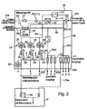
- FIG. 2 shows the control unit 16 in detail.
- the control unit 16 is connected via a connection 20a to the energy store 4a of the starter split circuit 6a and via a connection 20b and 20c to the energy store 4b or the generator 10 of the consumer subcircuit 6b.
- the consumers 2 and the consumers 2 classified as safety-relevant are fed by means of the consumer subcircuit 6b of the vehicle electrical system 6.
- the consumer 2 or 2 'to supply them via switched connections 20d or unswitched connections 20e connected to the consumer subcircuit 6b.
- these may be formed secured or unsecured.
- Particularly safety-relevant connections 20a to 20e for example the connection 20c, can be secured by a fuse 21, for example a so-called pyrotechnic fuse.
- the control unit 16 comprises at least one measuring means 22 for detecting operating variables B characterizing the respective subcircuits 6a or 6b.
- operating variable B current I, voltage U and / or time are for example by means of the measuring means 22 t recorded.
- the measuring means 22 of the respective pitch circle 6a or 6b comprises, for example, a voltmeter, an ammeter and / or a timer.
- the respective state of the associated energy store 4a or 4b is determined and determined.
- safety-relevant 2 ' For a redundant connection of consumers classified as safety-relevant 2 ', these are additionally connected to the consumer subcircuit 6b by means of the additional coupling element 14 to the starter subcircuit 6a.
- the control unit 16 per safety-relevant consumer 2 'on an associated coupling element 14.
- the safety-relevant consumers 2 ' by means of the respective additional Coupling element 14 completely or largely quiescent current coupled to the star split circuit 6a.
- the arrangement allows a in vehicle operation by the enabled, additional coupling elements 14 to the safety-relevant consumer 2 'applied voltage of the energy storage 4a (starter battery) currentless monitoring the supply of the safety-relevant consumer 2' by the star split circuit 6a regardless of whether the consumer subcircuit 6b suddenly fails or still intact. Any errors are detected and displayed in good time.
- the described arrangement shows a three-stage supply concept with largely independent supply possibilities, wherein the special value of the arrangement exists. The first stage is the normal operation with supply of the safety-relevant consumer 2 'by consumer subcircuit 6b and monitoring the availability of the supply of the safety-relevant consumer 2' by the star split circle 6a via an associated coupling element 14.
- the consumer subcircuit can 6b via the coupling element 12 "from the starter battery and the starter subcircuit 6a to ensure the entire supply, this represents stage 2. If a large defect with total failure of the consumer subcircuit 6b takes effect, separation of the coupling element 12" or a fuse in addition to the coupling element 12 "achieves a separation of the star split circuit 6a and the consumer subcircuit 6b and supplies the safety-relevant consumer 2 'only from the starter battery via the star split circuit 6a s complete path of supply and emergency care creates a highly available supply.
- the respective coupling element 14 preferably comprises a field effect transistor 24 and a diode 26 and, in parallel, a resistor 28.
- a further field effect transistor 30 may be provided.
- the current Is can be supplied as the operating variable B of the respective safety-relevant consumer 2 ', and the voltage Uc can be fed to the data processing unit 18 via a further connection 34.
- both the pitch circuits 6a, 6b and the safety-relevant consumers 2 ' are continuously monitored.
- the data processing unit 18 on the basis of the acquired data of the operating variables B (U, I, t) of the pitch circles 6a, 6b and the safety-relevant consumer 2 ', the amount of charge removed per consumer 2' is determined, by means of which then by means of control signals in dependence on the capacity of the energy store 4a or 4b and / or the order of precedence of the consumer classified as safety-relevant 2 ⁇ this is switched on and / or off.
- this is also called a consumer battery, e.g. in the event of failure, the relevant safety-relevant consumer 2 'is connected to the star split circuit 6a and thus to the energy storage device 4a designed as a starter battery for emergency supply.
- the safety-relevant consumers 2 ' are coupled largely free of static current.
- the capacity limit of the starter battery 4 a is undershot, is by controlling respective coupling elements 14 of the respective safety-relevant consumer 2 'a rank sequential shutdown of individual consumers 2' possible.
- the respective safety-relevant consumer 2 ' can be assigned an amount of energy, in particular the required current, by means of control signals.
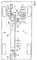
- FIG. 3 shows an arrangement 1 for a vehicle electrical system in a vehicle 36.
- the partial circuits 6a and 6b are arranged spatially separated from one another.
- the control unit 16 is also arranged in a particularly accident-safe location in the vehicle 36.
- the energy stores 4a and 4b can be dimensioned such that they have only interconnected the charge amount required for a cold start.
- a switching element 38 which couples the two energy storage 4a and 4b together, is provided.
- Such dimensioning of the energy storage 4a and 4b in terms of low individual capacity allows low cost and in particular a low weight.
Landscapes
- Engineering & Computer Science (AREA)
- Power Engineering (AREA)
- Transportation (AREA)
- Mechanical Engineering (AREA)
- Life Sciences & Earth Sciences (AREA)
- Sustainable Development (AREA)
- Sustainable Energy (AREA)
- Charge And Discharge Circuits For Batteries Or The Like (AREA)
- Control Of Charge By Means Of Generators (AREA)
Claims (12)
- Système (1) pour l'alimentation en tension de plusieurs consommateurs d'énergie (2, 2'), notamment d'un véhicule (36), avec un réseau de bord (6) comprenant au moins deux accumulateurs d'énergie (4a, 4b) dont un premier accumulateur d'énergie (4a) est relié dans un circuit partiel de démarrage (6a) à un démarreur (8) pour démarrer un moteur, et dont un deuxième accumulateur d'énergie (4b) est relié dans un circuit partiel de consommateurs d'énergie (6b) au consommateur d'énergie (2, 2'), dans lequel on a développé un dispositif de commande (16) comportant :- un élément de couplage (12), permettant de relier le circuit partiel de démarrage (6a) au circuit partiel des consommateurs d'énergie (6b),- des éléments de couplage supplémentaires (14), chacun permettant de relier respectivement un consommateur d'énergie (2') qualifié comme relevant de la sécurité, au circuit partiel de démarrage (6a), et- un moyen de mesure (22) pour enregistrer des données à l'aide desquelles une unité de traitement des données (18) du dispositif de commande (16) peut déterminer l'état des accumulateurs d'énergie (4a, 4b) d'un circuit partiel respectif (6a, 6b),caractérisé en ce que le moyen de mesure (22) enregistre d'autres données (32, 34) fournissant des informations concernant un courant (Is) vers un consommateur d'énergie relevant de la sécurité (2') ainsi qu'une tension (Uc) représentant la chute à travers un consommateur d'énergie relevant de la sécurité (2'), de telle sorte que l'unité de traitement des données (18) surveille en permanence l'état des accumulateurs d'énergie (4a, 4b) des circuits partiels (6a, 6b) ainsi que le consommateur d'énergie relevant de la sécurité (2') et le chemin vers les consommateurs d'énergie relevant de la sécurité (2'), et qu'elle puisse actionner une connexion de l'élément de couplage (12) et/ou des éléments de couplage supplémentaires (14) en réponse à cet état.
- Système selon la revendication 1, caractérisé en ce que l'unité de traitement des données (18) du dispositif de commande (16) utilise la tension du premier accumulateur d'énergie (4a) appliquée aux consommateurs d'énergie relevant de la sécurité (2') respectifs par l'intermédiaire des éléments de couplage (14) correspondants branchés en mode ouvert indépendamment de l'état du circuit partiel des consommateurs d'énergie (6b), pour la surveillance sans courant et pour la détermination de la disponibilité d'une alimentation pour le consommateur d'énergie relevant de la sécurité (2') respectif et en ce que le dispositif de commande actionne un élément de couplage (12"), ou un fusible à côté de l'élément de couplage (12"), en fonction de la disponibilité déterminée de l'alimentation.
- Système selon la revendication 1 ou 2,
caractérisé en ce que- en fonctionnement normal, le dispositif de commande (16) actionne la commutation de l'élément de couplage (12, 12") de telle sorte que les consommateurs d'énergie relevant de la sécurité (2') ne sont alimentés que par l'intermédiaire du circuit partiel des consommateurs d'énergie (6b) lorsqu'il est déterminé que le circuit partiel des consommateurs d'énergie (6b) est pleinement utilisable,- dans un deuxième mode de fonctionnement, le dispositif de commande (16) actionne la commutation de l'élément de couplage (12, 12") de telle sorte que le circuit partiel des consommateurs d'énergie (6b) s'appuie sur le premier accumulateur d'énergie (4a) et sur le circuit partiel de démarrage (6a) par l'intermédiaire de l'élément de couplage (12") pour assurer la totalité de l'alimentation lorsqu'il est déterminé que le circuit partiel des consommateurs d'énergie (6b) n'est pas pleinement utilisable, et- dans un troisième mode de fonctionnement, le dispositif de commande (16) actionne la commutation de l'élément de couplage (12") de telle sorte que l'élément de couplage (12") soit séparé ou qu'un fusible à côté de l'élément de couplage (12") assure une séparation du circuit partiel de démarrage (6a) et du circuit partiel des consommateurs d'énergie (6b), et que le consommateur d'énergie relevant de la sécurité (2') ne soit plus alimenté que par l'intermédiaire du circuit partiel de démarrage (6a) à partir de la première source d'énergie (4a) lorsqu'il est déterminé que le circuit partiel des consommateurs d'énergie (6b) est totalement hors service. - Système selon une des revendications 1 à 3, caractérisé en ce qu'à partir des données (32, 34), l'unité de traitement des données détermine une quantité de charge prélevée par chaque consommateur d'énergie relevant de la sécurité (2') et, en fonction de l'état de l'accumulateur d'énergie (4a, 4b) et/ou d'un ordre de priorité du consommateur d'énergie relevant de la sécurité (2') concerné, elle peut actionner l'élément de couplage (12) et/ou les éléments de couplage supplémentaires (14) et/ou elle peut brancher et/ou débrancher le consommateur d'énergie relevant de la sécurité (2').
- Système selon une des revendications 1 à 4, caractérisé en ce que le consommateur d'énergie relevant de la sécurité (2') est relié par l'intermédiaire de l'élément de couplage (12) au premier accumulateur d'énergie (4a) lorsque l'unité de traitement des données (18) détermine que le deuxième accumulateur d'énergie (4b) a passé au-dessous d'une limite de capacité ou qu'il est hors service.
- Système selon la revendication 5, caractérisé en ce que l'élément de couplage supplémentaire (14) respectif des consommateurs d'énergie relevant de la sécurité (2') est actionné de telle sorte qu'un débranchement par ordre de priorité des consommateurs d'énergie individuels relevant de la sécurité (2') a lieu lorsque l'unité de traitement des données (18) détermine que la capacité du premier accumulateur d'énergie (4a) a également passé au-dessous d'une limite.
- Système selon une des revendications 1 à 6, caractérisé en ce que l'unité de traitement des données (18) détermine, à partir des données qui lui sont acheminées, quelle quantité d'énergie est nécessaire pour le consommateur d'énergie respectif relevant de la sécurité (2'), et assure que seule cette quantité d'énergie est acheminée au consommateur d'énergie relevant de la sécurité (2').
- Système selon une des revendications 1 à 7, caractérisé en ce que les consommateurs d'énergie relevant de la sécurité (2') sont accouplés au circuit partiel de démarrage (6a) au moyen de l'élément de couplage supplémentaire (14) totalement ou en grande partie sans courant de repos.
- Système selon une des revendications 1 à 8, caractérisé en ce que le dispositif de commande (16) connecte les consommateurs d'énergie (2) et/ou les consommateurs d'énergie relevant de la sécurité (2') en fonction des données enregistrées.
- Système selon une des revendications 1 à 9, caractérisé en ce que l'élément de couplage supplémentaire (14) comporte au moins un transistor à effet de champ (24) et une diode (26).
- Système selon une des revendications 1 à 10, caractérisé en ce que l'élément de couplage (12) est réalisé sous la forme d'un commutateur (12") ou d'un convertisseur de courant continu (12').
- Système selon une des revendications 1 à 11, caractérisé en ce que les accumulateurs d'énergie (4a, 4b) sont dimensionnés de telle sorte que ceux-ci ne possèdent la quantité de charge nécessaire pour un démarrage à froid d'un moteur à combustion que lorsqu'ils sont accouplés.
Applications Claiming Priority (3)
| Application Number | Priority Date | Filing Date | Title |
|---|---|---|---|
| DE10225951 | 2002-06-11 | ||
| DE10225951 | 2002-06-11 | ||
| PCT/DE2003/001643 WO2003105330A2 (fr) | 2002-06-11 | 2003-05-21 | Systeme pour alimenter en tension plusieurs recepteurs et dispositif de commande destine a un reseau de bord comprenant au moins deux accumulateurs d'energie |
Publications (3)
| Publication Number | Publication Date |
|---|---|
| EP1512209A2 EP1512209A2 (fr) | 2005-03-09 |
| EP1512209B1 true EP1512209B1 (fr) | 2007-11-28 |
| EP1512209B8 EP1512209B8 (fr) | 2008-01-23 |
Family
ID=29718970
Family Applications (1)
| Application Number | Title | Priority Date | Filing Date |
|---|---|---|---|
| EP03756946A Expired - Lifetime EP1512209B8 (fr) | 2002-06-11 | 2003-05-21 | Systeme pour alimenter en tension plusieurs recepteurs et dispositif de commande destine a un reseau de bord comprenant au moins deux accumulateurs d'energie |
Country Status (5)
| Country | Link |
|---|---|
| US (1) | US7236893B2 (fr) |
| EP (1) | EP1512209B8 (fr) |
| JP (1) | JP4036220B2 (fr) |
| DE (2) | DE50308696D1 (fr) |
| WO (1) | WO2003105330A2 (fr) |
Cited By (1)
| Publication number | Priority date | Publication date | Assignee | Title |
|---|---|---|---|---|
| WO2023025897A1 (fr) * | 2021-08-27 | 2023-03-02 | Zf Friedrichshafen Ag | Dispositif électrique pour un véhicule automobile |
Families Citing this family (43)
| Publication number | Priority date | Publication date | Assignee | Title |
|---|---|---|---|---|
| JP4254658B2 (ja) * | 2004-08-23 | 2009-04-15 | 株式会社デンソー | 車載電源システム |
| DE102006007960A1 (de) * | 2006-02-21 | 2007-09-06 | Volkswagen Ag | Fahrzeugmotor-Steuervorrichtung für einen Elektro-Fahrzeugmotor |
| DE102006044108A1 (de) * | 2006-09-20 | 2008-03-27 | Man Nutzfahrzeuge Ag | Anordnung zum Laden von zumindest einer Akkumulatoreinheit in einem Fahrzeug |
| DE102008003835B3 (de) * | 2008-01-10 | 2009-07-16 | Continental Automotive Gmbh | Kraftfahrzueg-Spannungsversorgungsschaltung und Verfahren zum Betrieb einer Kraftfahrzeug-Spannungsversorgungsschaltung |
| DE102008031270B4 (de) * | 2008-07-02 | 2017-06-08 | Continental Automotive Gmbh | Steuergerät zur Absicherung eines Ausfalls einer Schaltvorrichtung bei Spannungswandlern in Kraftfahrzeugen |
| US7977813B2 (en) * | 2008-12-11 | 2011-07-12 | Caterpillar Inc. | System and method for reducing quiescent power draw and machine using same |
| EP2221941B1 (fr) | 2009-02-19 | 2012-11-07 | Delphi Technologies, Inc. | Dispositif de protection de déchargement |
| JP2010207061A (ja) * | 2009-03-06 | 2010-09-16 | Denso Corp | 車両用電源システム |
| EP2272722B1 (fr) * | 2009-07-01 | 2015-04-08 | Denso Corporation | Appareil de source d'alimentation pour véhicule |
| DE102009050126B4 (de) * | 2009-10-21 | 2012-09-13 | Continental Automotive Gmbh | Bordnetz für ein Kraftfahrzeug |
| DE102010001244A1 (de) * | 2010-01-27 | 2011-07-28 | SB LiMotive Company Ltd., Kyonggi | Batteriesystem für Mikro-Hybridfahrzeuge mit Hochleistungsverbrauchern |
| DE102010001243A1 (de) * | 2010-01-27 | 2011-07-28 | SB LiMotive Company Ltd., Kyonggi | Batteriesystem für μ-Hybridfahrzeuge mit Hochleistungsverbrauchern |
| DE102010013569A1 (de) | 2010-03-30 | 2011-10-06 | Gm Global Technology Operations Llc (N.D.Ges.D. Staates Delaware) | Versorgungsschaltung für die elektrische Versorgung eines Fahrzeugs |
| DE102010029788B4 (de) * | 2010-06-08 | 2023-05-25 | Bayerische Motoren Werke Aktiengesellschaft | Bordnetz und Verfahren und Vorrichtung zum Betreiben des Bordnetzes |
| DE102010026772A1 (de) | 2010-07-10 | 2012-01-12 | Gm Global Technology Operations Llc (N.D.Ges.D. Staates Delaware) | Notfallenergieversorgung für ein Fahrzeug |
| DE102010054191A1 (de) * | 2010-12-11 | 2012-06-21 | Volkswagen Ag | Kraftfahrzeugbordnetz und Verfahren zum Betreiben eiens Kraftfahrzeugbordnetzes |
| US8606444B2 (en) * | 2010-12-29 | 2013-12-10 | Caterpillar Inc. | Machine and power system with electrical energy storage device |
| DE102011101531B4 (de) | 2011-05-14 | 2015-09-24 | Volkswagen Aktiengesellschaft | Kraftfahrzeugbordnetz und Verfahren zum Betreiben eines Kraftfahrzeugbordnetzes |
| EP2538068B1 (fr) | 2011-06-22 | 2017-11-08 | Volvo Car Corporation | Procédé et agencement pour améliorer la performance d'un système électrique de véhicule |
| DE102012200804A1 (de) * | 2012-01-20 | 2013-07-25 | Continental Automotive Gmbh | Bordnetz und Verfahren zum Betreiben eines Bordnetzes |
| DE102012200823A1 (de) * | 2012-01-20 | 2013-07-25 | Robert Bosch Gmbh | Bordnetz mit Gleichspannungswandler, Steuereinrichtung und zugehöriges Betriebsverfahren |
| DE102012015525A1 (de) * | 2012-08-04 | 2014-02-06 | Audi Ag | Kraftwagen mit robuster Niedervolt-Spannungsversorgung |
| FR2996374B1 (fr) * | 2012-10-03 | 2016-10-28 | Valeo Systemes De Controle Moteur | Reseau electrique pour vehicule automobile |
| FR3002087A1 (fr) * | 2013-02-12 | 2014-08-15 | Peugeot Citroen Automobiles Sa | Batterie de servitude pour un vehicule |
| DE102013204238B4 (de) * | 2013-03-12 | 2025-07-17 | Bayerische Motoren Werke Aktiengesellschaft | Vorrichtung zur stabilisierenden Versorgung eines Verbrauchers |
| DE102013206299A1 (de) * | 2013-04-10 | 2014-04-10 | Robert Bosch Gmbh | Mehrspannungsbordnetz für Kraftfahrzeug sowie Verfahren zum Betreiben eines derartigen Mehrspannungsbordnetzes und Mittel zu dessen Implementierung |
| EP3013617A4 (fr) * | 2013-06-28 | 2017-11-08 | CAP-XX Limited | Système de commande pour un moteur automobile et procédé de commande d'un moteur automobile |
| FR3013167B1 (fr) * | 2013-11-12 | 2015-12-25 | Peugeot Citroen Automobiles Sa | Dispositif et procede de recharge d'un stockeur d'energie electrique d'un vehicule automobile |
| DE102013225097B4 (de) * | 2013-12-06 | 2020-10-29 | Volkswagen Aktiengesellschaft | Energiemanagementverfahren zum Betreiben eines elektrischen Bordnetzes eines Kraftfahrzeuges und Kraftfahrzeug |
| DE102014203030B4 (de) * | 2014-02-19 | 2021-06-02 | Vitesco Technologies GmbH | Verfahren zum gesteuerten Verbinden mehrerer Bordnetzzweige eines Fahrzeugs, Steuereinheit zur Ausführung des Verfahrens sowie Fahrzeugbordnetz |
| DE102014208201A1 (de) * | 2014-04-30 | 2015-11-05 | Robert Bosch Gmbh | Vorrichtung zur Versorgung zumindest eines Verbrauchers |
| DE102014219138A1 (de) * | 2014-09-23 | 2016-03-24 | Robert Bosch Gmbh | Bordnetz |
| DE102014219133A1 (de) * | 2014-09-23 | 2016-03-24 | Robert Bosch Gmbh | Bordnetz |
| DE102014221281A1 (de) * | 2014-10-21 | 2016-04-21 | Bayerische Motoren Werke Aktiengesellschaft | Fahrzeug-Bordnetz mit hoher Verfügbarkeit |
| DE102015008881A1 (de) * | 2015-07-09 | 2017-01-12 | Daimler Ag | Integration von Starterstromsteuerung und Bordnetztrennschalter |
| JP6268145B2 (ja) * | 2015-11-16 | 2018-01-24 | オムロンオートモーティブエレクトロニクス株式会社 | 回生システムおよび回生システムの制御方法 |
| EP3394422B1 (fr) * | 2015-12-21 | 2024-02-14 | Volvo Truck Corporation | Méthode de gestion d'un système de puissance dans un véhicule pourvu de deux batteries |
| US9842718B1 (en) * | 2016-06-10 | 2017-12-12 | Sumitomo Wiring Systems, Ltd. | Fuse array for vehicle electrical system having multiple discrete circuits |
| DE102018215835A1 (de) * | 2018-09-18 | 2020-03-19 | Conti Temic Microelectronic Gmbh | Zugangssystem und Verfahren zur Zugangsverifizierung |
| US11183938B2 (en) * | 2018-11-14 | 2021-11-23 | Toshiba International Corporation | Hybrid PV inverter with SCIB battery integration |
| DE102020208401A1 (de) | 2020-07-03 | 2022-01-05 | Robert Bosch Gesellschaft mit beschränkter Haftung | Verfahren zur Absicherung insbesondere sicherheitsrelevanter Verbraucher in einem Kraftfahrzeug |
| DE102021200578B4 (de) | 2021-01-22 | 2025-09-25 | Volkswagen Aktiengesellschaft | Kraftfahrzeugbordnetz |
| DE102021208935A1 (de) * | 2021-08-16 | 2023-02-16 | Robert Bosch Gesellschaft mit beschränkter Haftung | Vorrichtung zum Überwachen eines Leistungsverteilers eines Kraftfahrzeugs |
Family Cites Families (13)
| Publication number | Priority date | Publication date | Assignee | Title |
|---|---|---|---|---|
| EP0435628B1 (fr) * | 1989-12-25 | 1994-10-26 | Matsushita Electric Works, Ltd. | Dispositif d'onduleur |
| DE4028242C2 (de) | 1990-09-06 | 1997-08-07 | Bayerische Motoren Werke Ag | Bordnetz für Kraftfahrzeuge |
| US5488283A (en) * | 1993-09-28 | 1996-01-30 | Globe-Union, Inc. | Vehicle battery system providing battery back-up and opportunity charging |
| FR2739733A1 (fr) | 1995-10-06 | 1997-04-11 | Peugeot | Dispositif d'alimentation electrique a deux batteries pour vehicule automobile a moteur thermique |
| DE19628222A1 (de) | 1996-07-15 | 1998-01-22 | Bosch Gmbh Robert | Vorrichtung zur Spannungsversorgung in einem Kraftfahrzeug |
| DE19645944A1 (de) | 1996-11-07 | 1998-05-14 | Bosch Gmbh Robert | Steuergerät für ein Bordnetz |
| DE59912054D1 (de) | 1998-02-18 | 2005-06-16 | Brose Schliesssysteme Gmbh | Vorrichtung zur elektrischen Energieversorgung |
| US6321707B1 (en) * | 1998-11-12 | 2001-11-27 | James Dunn | Multifunction auxiliary vehicle power and starter system |
| DE19921451C1 (de) | 1999-05-08 | 2000-11-30 | Daimler Chrysler Ag | Bordnetz bei Kraftfahrzeugen |
| DE19951128A1 (de) | 1999-10-23 | 2001-04-26 | Bosch Gmbh Robert | Verfahren und Vorrichtung zur Spannungsregelung |
| DE19955721A1 (de) * | 1999-11-15 | 2001-05-17 | Volkswagen Ag | Zwei-Batteriensystem |
| DE10014243B4 (de) | 2000-03-22 | 2004-11-04 | Volkswagen Ag | Zwei-Batteriensystem |
| DE10033317B4 (de) | 2000-06-29 | 2011-08-11 | Volkswagen AG, 38440 | Kraftfahrzeugbordnetz mit sicherheitsrelevanten Verbrauchern |
-
2003
- 2003-05-21 WO PCT/DE2003/001643 patent/WO2003105330A2/fr not_active Ceased
- 2003-05-21 DE DE50308696T patent/DE50308696D1/de not_active Expired - Lifetime
- 2003-05-21 DE DE2003122875 patent/DE10322875A1/de not_active Withdrawn
- 2003-05-21 JP JP2004512278A patent/JP4036220B2/ja not_active Expired - Lifetime
- 2003-05-21 US US10/517,437 patent/US7236893B2/en not_active Expired - Lifetime
- 2003-05-21 EP EP03756946A patent/EP1512209B8/fr not_active Expired - Lifetime
Cited By (1)
| Publication number | Priority date | Publication date | Assignee | Title |
|---|---|---|---|---|
| WO2023025897A1 (fr) * | 2021-08-27 | 2023-03-02 | Zf Friedrichshafen Ag | Dispositif électrique pour un véhicule automobile |
Also Published As
| Publication number | Publication date |
|---|---|
| US7236893B2 (en) | 2007-06-26 |
| DE10322875A1 (de) | 2004-01-08 |
| JP4036220B2 (ja) | 2008-01-23 |
| EP1512209B8 (fr) | 2008-01-23 |
| JP2005533702A (ja) | 2005-11-10 |
| WO2003105330A3 (fr) | 2004-02-19 |
| WO2003105330A2 (fr) | 2003-12-18 |
| EP1512209A2 (fr) | 2005-03-09 |
| US20050267697A1 (en) | 2005-12-01 |
| DE50308696D1 (de) | 2008-01-10 |
Similar Documents
| Publication | Publication Date | Title |
|---|---|---|
| EP1512209B1 (fr) | Systeme pour alimenter en tension plusieurs recepteurs et dispositif de commande destine a un reseau de bord comprenant au moins deux accumulateurs d'energie | |
| EP1232073B1 (fr) | Systeme a deux batteries | |
| DE102018205977B4 (de) | Energieverteilungssystem | |
| EP1561269B1 (fr) | Reseau de bord destine a alimenter au moins un recepteur presentant des exigences elevees en matiere de disponibilite du reseau de bord | |
| DE102018210943B4 (de) | Bordnetz für ein Fahrzeug sowie Fahrzeug | |
| EP2516197B1 (fr) | Procédé et dispositif pour le déchargement d'un accumulateur d'énergie dans un réseau de haute tension | |
| EP1302371B1 (fr) | Alimentation redondante d'énergie pour des comsommateurs de sécurité dans un réseau de bord | |
| EP3138175B1 (fr) | Dispositif de transfert d'énergie et réseau de bord | |
| DE102011005729B4 (de) | Fahrzeugenergiesystem | |
| WO2014086651A2 (fr) | Procédé pour une liaison commandée de plusieurs branches d'un réseau de bord d'un véhicule, unité de commande pour exécuter le procédé ainsi que réseau de bord | |
| EP1411364A1 (fr) | Tableau de bord d'un véhicule pour identifier l'état de batterie connectée au pôle positif de la batterie | |
| EP1378401B1 (fr) | Dispositif d'alimentation en énergie électrique | |
| DE102022126434A1 (de) | Schaltungsgetriggerte fehlerabschwächung für ein batterieelektrisches system und ein kraftfahrzeug, das dasselbe aufweist | |
| DE69813862T2 (de) | Verfahren und einrichtung zur ladesteuerung in einem elektrischen system mit zwei batterien | |
| DE102018105826B4 (de) | Elektrisches versorgungssystem und verfahren | |
| EP2892751B1 (fr) | Système de batterie pour faire fonctionner des consommateurs électriques dans un véhicule servant au transport de produits dangereux | |
| DE4219398A1 (de) | Gepufferte Spannungsversorgung für Bordelektronik | |
| EP1318590B1 (fr) | Dispositif d'alimentation de puissance avec deux batteries et deux générateurs dans un véhicule utilitaire | |
| EP4385789A1 (fr) | Dispositif de sécurité et procédé de sécurité avec une unité de séparation pour la batterie d'un véhicule automobile à propulsion électrique | |
| EP3649680A1 (fr) | Appareil de commande principale pour un système de batterie | |
| DE102018210979B4 (de) | Mehrspannungsbatterievorrichtung und Mehrspannungsbordnetz für ein Kraftfahrzeug | |
| EP3904163A1 (fr) | Agencement de commande pour une batterie haute tension et procédé de fonctionnement d'un agencement de commande | |
| DE102024002043B4 (de) | Elektrisches Bordnetz für ein Fahrzeug und Verfahren zum Betrieb eines Bordnetzes | |
| DE102022204687B4 (de) | Bordnetz für ein elektrisch angetriebenes Kraftfahrzeug | |
| DE102009018011A1 (de) | Vorrichtung zur Verteilung von elektrischer Energie in einem Fahrzeug |
Legal Events
| Date | Code | Title | Description |
|---|---|---|---|
| PUAI | Public reference made under article 153(3) epc to a published international application that has entered the european phase |
Free format text: ORIGINAL CODE: 0009012 |
|
| 17P | Request for examination filed |
Effective date: 20041203 |
|
| AK | Designated contracting states |
Kind code of ref document: A2 Designated state(s): AT BE BG CH CY CZ DE DK EE ES FI FR GB GR HU IE IT LI LU MC NL PT RO SE SI SK TR |
|
| RIN1 | Information on inventor provided before grant (corrected) |
Inventor name: GROSS, CHRISTOF Inventor name: LOEWEL, ANDREAS Inventor name: KOENIG, JOCHEN Inventor name: PETRY, FRANZ-JOSEF |
|
| RBV | Designated contracting states (corrected) |
Designated state(s): DE FR GB IT |
|
| RAP1 | Party data changed (applicant data changed or rights of an application transferred) |
Owner name: DAIMLERCHRYSLER AG |
|
| GRAP | Despatch of communication of intention to grant a patent |
Free format text: ORIGINAL CODE: EPIDOSNIGR1 |
|
| GRAS | Grant fee paid |
Free format text: ORIGINAL CODE: EPIDOSNIGR3 |
|
| GRAA | (expected) grant |
Free format text: ORIGINAL CODE: 0009210 |
|
| AK | Designated contracting states |
Kind code of ref document: B1 Designated state(s): DE FR GB IT |
|
| REG | Reference to a national code |
Ref country code: GB Ref legal event code: FG4D Free format text: NOT ENGLISH |
|
| RAP2 | Party data changed (patent owner data changed or rights of a patent transferred) |
Owner name: DAIMLER AG |
|
| REF | Corresponds to: |
Ref document number: 50308696 Country of ref document: DE Date of ref document: 20080110 Kind code of ref document: P |
|
| GBV | Gb: ep patent (uk) treated as always having been void in accordance with gb section 77(7)/1977 [no translation filed] | ||
| EN | Fr: translation not filed | ||
| PLBE | No opposition filed within time limit |
Free format text: ORIGINAL CODE: 0009261 |
|
| STAA | Information on the status of an ep patent application or granted ep patent |
Free format text: STATUS: NO OPPOSITION FILED WITHIN TIME LIMIT |
|
| PG25 | Lapsed in a contracting state [announced via postgrant information from national office to epo] |
Ref country code: FR Free format text: LAPSE BECAUSE OF FAILURE TO SUBMIT A TRANSLATION OF THE DESCRIPTION OR TO PAY THE FEE WITHIN THE PRESCRIBED TIME-LIMIT Effective date: 20080912 |
|
| 26N | No opposition filed |
Effective date: 20080829 |
|
| PG25 | Lapsed in a contracting state [announced via postgrant information from national office to epo] |
Ref country code: GB Free format text: LAPSE BECAUSE OF FAILURE TO SUBMIT A TRANSLATION OF THE DESCRIPTION OR TO PAY THE FEE WITHIN THE PRESCRIBED TIME-LIMIT Effective date: 20071128 |
|
| PG25 | Lapsed in a contracting state [announced via postgrant information from national office to epo] |
Ref country code: IT Free format text: LAPSE BECAUSE OF NON-PAYMENT OF DUE FEES Effective date: 20080531 |
|
| REG | Reference to a national code |
Ref country code: DE Ref legal event code: R081 Ref document number: 50308696 Country of ref document: DE Owner name: BURANI CONSULTING LIMITED LIABILITY COMPANY, US Free format text: FORMER OWNER: DAIMLER AG, 70327 STUTTGART, DE Effective date: 20120418 Ref country code: DE Ref legal event code: R081 Ref document number: 50308696 Country of ref document: DE Owner name: BURANI CONSULTING LIMITED LIABILITY COMPANY, W, US Free format text: FORMER OWNER: DAIMLER AG, 70327 STUTTGART, DE Effective date: 20120418 |
|
| PGFP | Annual fee paid to national office [announced via postgrant information from national office to epo] |
Ref country code: DE Payment date: 20140602 Year of fee payment: 12 |
|
| REG | Reference to a national code |
Ref country code: DE Ref legal event code: R119 Ref document number: 50308696 Country of ref document: DE |
|
| PG25 | Lapsed in a contracting state [announced via postgrant information from national office to epo] |
Ref country code: DE Free format text: LAPSE BECAUSE OF NON-PAYMENT OF DUE FEES Effective date: 20151201 |